
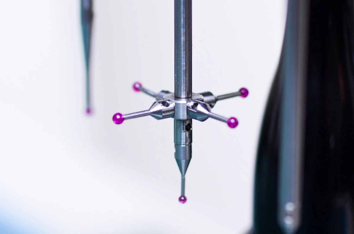

CMM inspection checks a CNC machined part by recording three-dimensional coordinates and comparing the measured geometry with the drawing or CAD model. It is useful for datum-based features, GD&T controls, complex surfaces, and dimensions that handheld tools cannot verify reliably.
A CMM does not prove every part requirement. Buyers must match the inspection method to the features that control fit, alignment, sealing, motion, or acceptance.
What Is CMM Inspection?
CMM inspection is dimensional measurement performed with a coordinate measuring machine. The machine tracks a tactile or optical sensor within an X, Y, and Z coordinate system. Metrology software turns the recorded points into planes, circles, cylinders, distances, angles, and surface profiles, then evaluates those features against the product definition. The result depends on the datum alignment, probe setup, fixturing, point pattern, environment, and evaluation method.
How Is CMM Inspection Performed?
CMM inspection starts with a drawing review. The inspector then sets up the part, captures coordinate data, and compares the results with the product definition. A technically clean measurement can still be wrong if the setup uses the wrong revision, datum reference frame, or acceptance rule.
Reviewing the Drawing and Defining the Inspection Plan
The inspection plan should resolve these items before programming begins:
- Released drawing and CAD model
- Part number, revision, material, and finish
- General tolerances, datum structure, and GD&T callouts
- Features assigned to the CMM and features assigned to other tools
- Sensor type, probe access, point distribution, and scanning paths
- Fixture method, sampling quantity, and report requirements
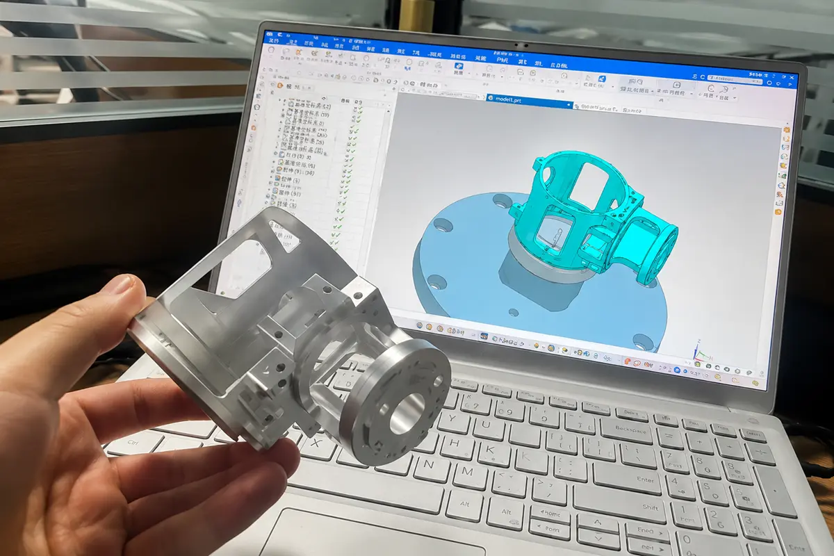
A 3D model can guide the CMM program, but it does not replace tolerances, datums, thread requirements, surface finish, or acceptance notes. The choice between STEP and STL manufacturing files also matters because a STEP model carries precise surfaces, while an STL file represents the part with a triangle mesh.
Preparing, Fixturing, and Aligning the Part
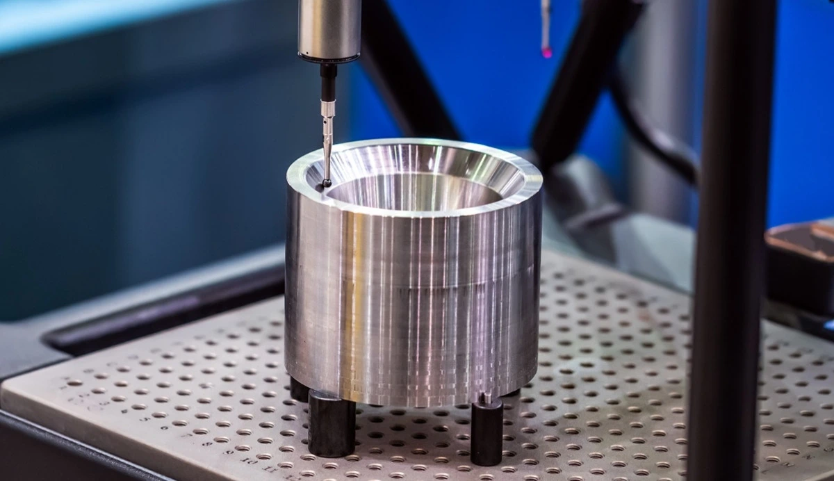
- Clean and stabilize the part. Remove chips, oil, and loose debris. Check for burrs or damage that could affect seating or probe contact. If thermal expansion could affect the result, allow the part to stabilize in the measurement environment.
- Fixture without distortion. Hold the part firmly enough to prevent movement, but limit clamp force on thin walls, plastics, and slender features. The probe must reach the required surfaces without contacting the fixture.
- Qualify the sensor and establish alignment. Qualify the stylus or optical sensor, then build the part coordinate system from the specified datum features. An alignment chosen for convenience can misrepresent the design requirement when it does not reproduce the drawing’s datum reference frame.
Capturing Coordinate Data With the Probe
A tactile probe records individual touch points or scans continuously along a surface. An optical sensor collects data without contact when the machine, surface, and inspection plan support that method. The software fits the recorded coordinates to geometric features or compares them with a CAD surface. Point placement affects the result because a sparse pattern may miss local waviness or a high spot. The probe strategy must also account for stylus stiffness, feature depth, collision risk, and surface access.
Comparing the Results With the Drawing or CAD Model
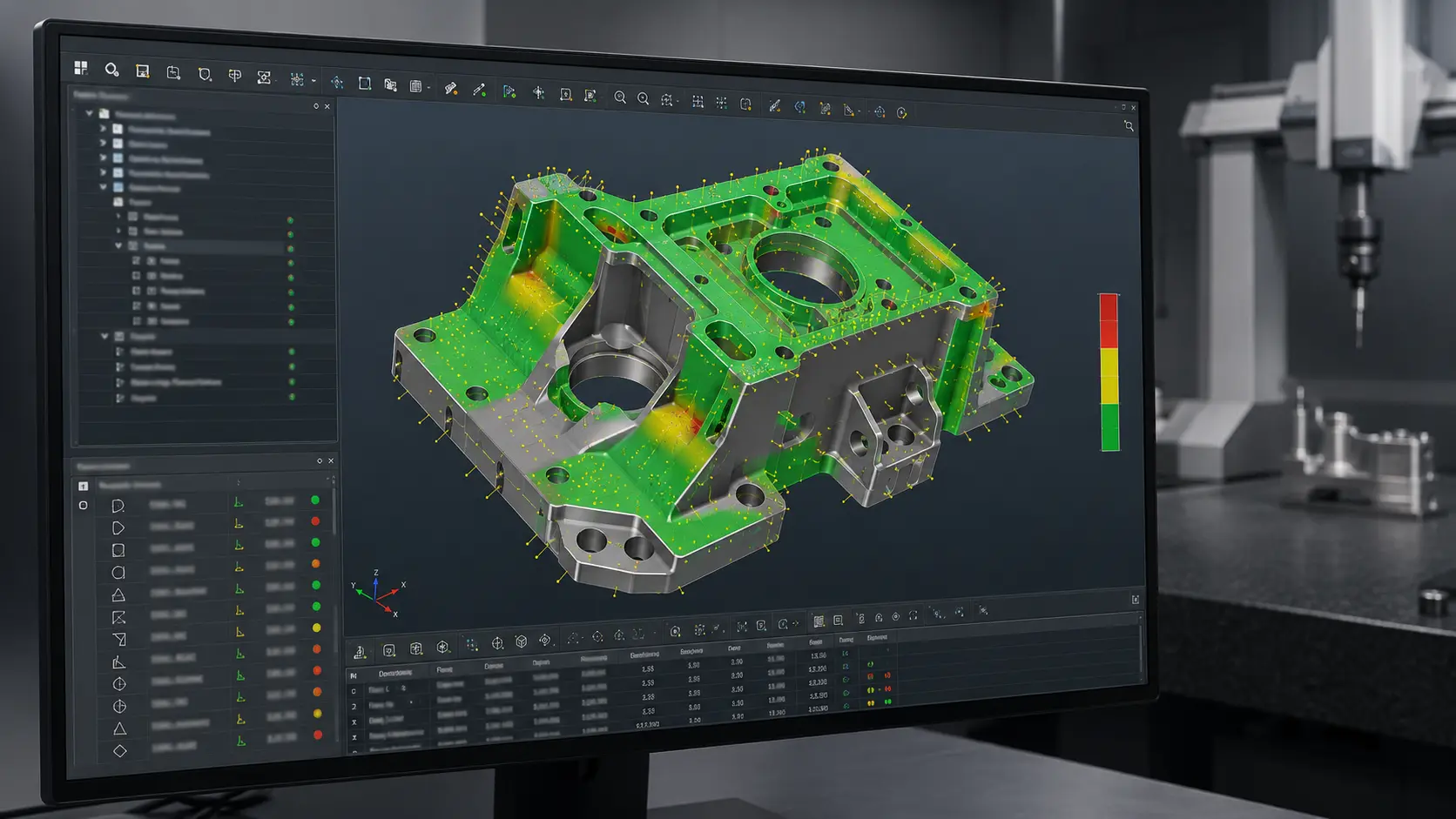
The software compares each evaluated feature with its nominal value and tolerance. A usable report shows how the supplier reached the acceptance decision, rather than presenting only a color map or pass label.
| Report element | What the buyer should confirm |
|---|---|
| Part identity and revision | The report matches the released part number and product definition |
| Nominal, measured value, and deviation | The report ties the recorded result to the specified characteristic |
| Tolerance and status | The pass or fail decision uses the correct limits |
| Datum reference frame | GD&T results use the datums and order stated on the drawing |
| Measurement method | The report documents probe strategy, alignment, and any agreed evaluation settings when they affect acceptance |
What Can CMM Inspection Measure on CNC Machined Parts?
For CNC machining parts, a CMM can evaluate accessible prismatic and freeform geometry when the selected sensor and measurement uncertainty suit the tolerance. Other tools remain necessary when they check function or material properties more directly.
Size, Location, and Datum Relationships
A CMM can measure lengths, widths, heights, diameters, depths, center distances, hole patterns, and feature locations. The software can also construct axes, center planes, and intersections from measured features. Datum alignment lets the CMM evaluate relationships that drive assembly. A bore may meet its diameter tolerance yet sit in the wrong position relative to a mounting face, so size alone may not predict fit.
Flatness, Perpendicularity, Position, and Profile
Each geometric control answers a different inspection question. The CMM program must apply the control and datum rules stated on the drawing.
| GD&T control | What the CMM evaluates | Datum relationship |
|---|---|---|
| Flatness | Variation across one surface | No datum required |
| Perpendicularity | Orientation of a surface, axis, or center plane | Evaluated relative to the specified datum |
| Position | Location of a feature of size within its tolerance zone | Usually evaluated from the stated datum reference frame |
| Profile | Variation of a line or surface from the nominal contour | May control form alone or include orientation and location through referenced datums |
Alignment, point distribution, filtering, and feature fitting can change a reported GD&T value. Material-condition modifiers affect the permitted tolerance and evaluation rules, rather than the measured geometry itself. When a result sits near the limit, the report should preserve enough setup detail to support a technical review.
Complex Curves, Contours, and Freeform Surfaces
CMM scanning can collect dense point paths across contoured pockets, blended surfaces, angled bores, and other geometry that handheld tools cannot describe well. The software compares the measured surface with the CAD model. Access remains the main constraint. Deep channels, internal undercuts, small bores, and hidden surfaces may require another stylus, a rotary setup, an optical sensor, or a different inspection method. Early CAD review helps the supplier confirm access before finalizing the machining and inspection plans.
Features That Require Gauges or Other Inspection Tools
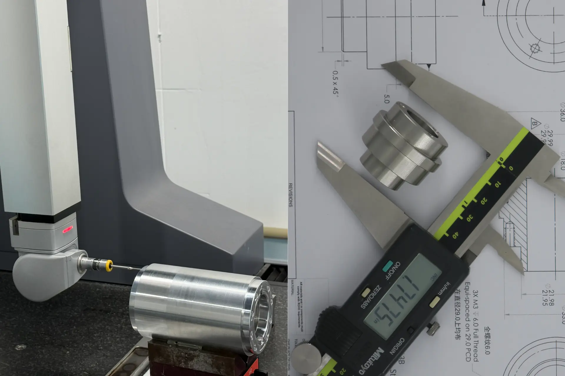
Use a dedicated gauge or test when it checks the functional requirement or material property more directly. A mating boundary or press fit tolerance may justify functional gauging even when the CMM records the bore and shaft dimensions.
| Feature or requirement | Common inspection tool | Why CMM data may not be enough |
|---|---|---|
| Internal and external threads | GO/NO-GO thread gauges or thread measurement tools | Accessible points may not prove functional engagement, pitch diameter, and thread form |
| Precision fits and small bores | Plug gauges, bore gauges, air gauges, or micrometers | A dedicated gauge may check size or mating function more directly |
| Surface roughness | Profilometer or surface roughness tester | Coordinate data does not replace an Ra or other texture measurement |
| Hardness and coating thickness | Hardness tester or coating thickness gauge | These are material or finish properties, not coordinate geometry |
| Burrs, scratches, contamination, and cosmetic defects | Visual or optical inspection | A dimensional result may pass while the surface fails another acceptance requirement |
When Should Buyers Request CMM Inspection?
Buyers should request CMM inspection when feature relationships, complex geometry, or recorded GD&T results affect acceptance. Inspectors can check simple open dimensions with wider tolerances faster by using calipers, micrometers, height gauges, or dedicated gauges.
First Articles and Manufacturing Process Changes
CMM inspection is appropriate when a new or changed process could alter critical geometry. Common triggers include:
- A new part or first production run
- A drawing or tolerance revision
- A new fixture or CNC program
- A machine transfer or major setup change
- A supplier or manufacturing route change
First article inspection is broader than CMM inspection. CMM results may supply dimensional evidence for the FAI, while material records, finish records, traceability, and results from other inspection tools complete the required package.
Tight-Tolerance and GD&T Controlled Features
Request CMM inspection when simpler tools cannot reliably verify datum-based position, profile, or orientation controls. The supplier should use a measurement method whose uncertainty supports the specified tolerance and document conditions that could affect a result near the limit. Buyers should confirm calibration status, environmental control, program validation, and the report format for critical characteristics before releasing the order.
Complex Parts With Assembly or Alignment Risk
CMM inspection suits parts whose surfaces, holes, or axes must work together. Examples include coaxial bearing bores, dowel holes that locate a housing, sealing faces tied to ports, optical mounts, robotic brackets, and semiconductor equipment components with a controlled datum structure. The inspection plan should reproduce the assembly datums and report the relationships that drive fit. A generic dimensional report may miss that requirement even when individual sizes pass.
Production Lots Requiring Sampling or Full Inspection
The inspection scope should state which characteristics inspectors measure and how often. Buyers should define “full inspection” in the RFQ because the phrase can refer to any of the four scopes below.
| Inspection scope | Measurements | When it fits |
|---|---|---|
| Lot sampling | Selected characteristics on a defined number of parts | A stable process with an agreed sampling plan and response to failure |
| Every-part inspection | Specified characteristics on each part | Features with higher assembly, compliance, or customer-acceptance risk |
| Every-characteristic inspection | All drawing requirements using the CMM and complementary tools | Orders that require a complete dimensional record for the inspected part or lot |
| Every part and every characteristic | All required checks on each part | Contractual or risk conditions that justify the highest inspection time and cost |
For inspection-heavy CNC orders, Rollyu Precision supports DFM review, CMM inspection, FAI, dimensional reports, and material traceability under ISO 9001:2015 and ISO 13485:2016 certified systems. The RFQ should identify critical features, sampling rules, report format, and any approval hold before production or shipment.
FAQs
What is the difference between CMM inspection and FAI?
CMM inspection is a measurement method, while FAI is a broader production approval process. A CMM can supply dimensional results for an FAI report. The FAI package may also include material records, finish records, drawing revision checks, traceability, and results from gauges or tests that a CMM cannot perform.
How much time and cost does CMM inspection add to an order?
CMM inspection has no standard time or price. The added effort depends on part size, feature count, tolerance, probe access, fixture needs, program development, report detail, and sample quantity. A repeat order with a validated program may need less setup, so buyers should request the inspection scope as a separate quote item.
Why can the same part produce different CMM inspection results?
The same part can produce different results when the measurement setup changes. Alignment, fixturing, temperature, probe configuration, point distribution, filtering, and feature-fitting methods can shift the reported value. Dirt, burrs, surface texture, or part movement can also contribute, so disputed results require a method and uncertainty review.
Can a part pass CMM inspection and still fail during assembly?
Yes, a part can pass its measured CMM characteristics and still fail in assembly. An unchecked thread, burr, surface finish, coating buildup, part deformation, mating-part variation, or incorrect datum interpretation may cause the failure. A CMM result covers only the characteristics and conditions included in the approved measurement plan.
Can a slightly out-of-tolerance CMM result still be accepted?
Only the buyer or authorized design authority should accept an out-of-tolerance result. Acceptance requires a documented deviation or use-as-is decision that considers measurement uncertainty, feature function, mating parts, affected quantity, and downstream risk. The approval should identify the exact characteristic, part or lot, revision, and permitted condition.
