
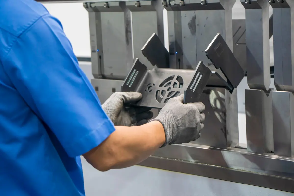

Set a sheet metal bend radius by matching the alloy, material condition, and thickness to a supported forming reference, then checking that radius against what the fabricator’s tooling produces. A radius equal to sheet thickness (R/t = 1) is a useful starting point for some combinations, not a universal minimum. The released design also needs clearance for the radius the part actually forms.
What Does Sheet Metal Bend Radius Measure?
Sheet metal bend radius normally means the inside radius, measured on the curved inner surface of the bend. Drawings and forming references express the bend in related terms:
- R/t ratio: the inside radius divided by sheet thickness, t. A 3 mm inside radius in 2 mm sheet gives R/t = 1.5.
- Drawing callout: R3 specifies a radius of three drawing units, which is 3 mm on a metric drawing, not three times the thickness.
- Outside radius: for an ideal bend with constant thickness, the inside radius plus t.
When a bracket wraps around another part, the mating surface determines whether the inside or outside radius controls clearance.
Minimum Bend Radius by Material and Thickness
A published minimum radius holds only for the material condition and thickness it was published for. The Aluminum Association lists alloy, temper, thickness, grain orientation, and bend angle as factors in selecting a radius large enough to avoid cracking, so a chart entry may not apply once any of those conditions changes.
Aluminum Alloy and Temper
Atlas Steels publishes these recommendations for 5052 sheet bent at 90 degrees to the rolling direction.
| Aluminum condition | Sheet thickness, t | Recommended minimum R/t | Corresponding inside radius |
|---|---|---|---|
| 5052-H32 | 1.6 mm (0.063 in) | 1 | 1.6 mm |
| 5052-H32 | 3.2 mm (0.126 in) | 1.5 | 4.8 mm |
| 5052-H34 | 1.6 mm (0.063 in) | 1.5 | 2.4 mm |
| 5052-H34 | 3.2 mm (0.126 in) | 2 | 6.4 mm |
Within this table, the harder H34 temper needs a larger ratio than H32 at the same thickness, and 3.2 mm sheet needs a larger ratio than 1.6 mm sheet in both tempers. The values are recommendations, not guaranteed forming limits; Atlas states that the achievable minimum also depends on bending equipment, tooling, and tooling condition. Read the row for the specified temper and thickness, and do not interpolate a missing thickness without a technical basis.
If the alloy is still undecided, compare 5052 aluminum vs. 6061 before assigning a radius, because a 5052-H32 recommendation does not establish a workable radius for 6061-T6.
Stainless Steel Families
Outokumpu gives general minimum inside-radius-to-thickness guidance of R/t = 1 for austenitic and ferritic stainless steels and R/t = 2 for duplex stainless steels in its discussion of open-die and closed-die bending. A single radius rule for all stainless steel is therefore too broad. Use these family-level ratios for preliminary selection only. For a tight bend, have the fabricator confirm the exact grade, supplied condition, thickness, and forming setup against the applicable material reference.
Why the Formed Radius Can Differ From the CAD Radius
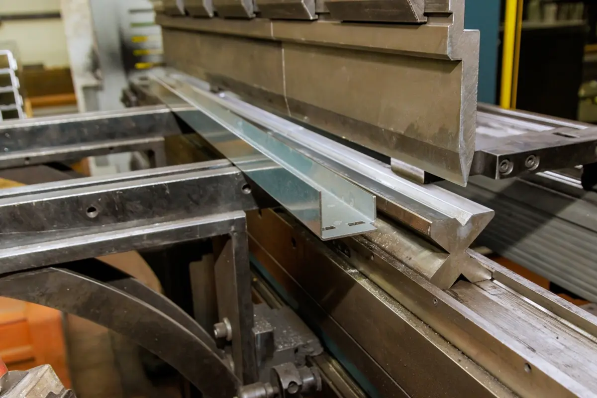
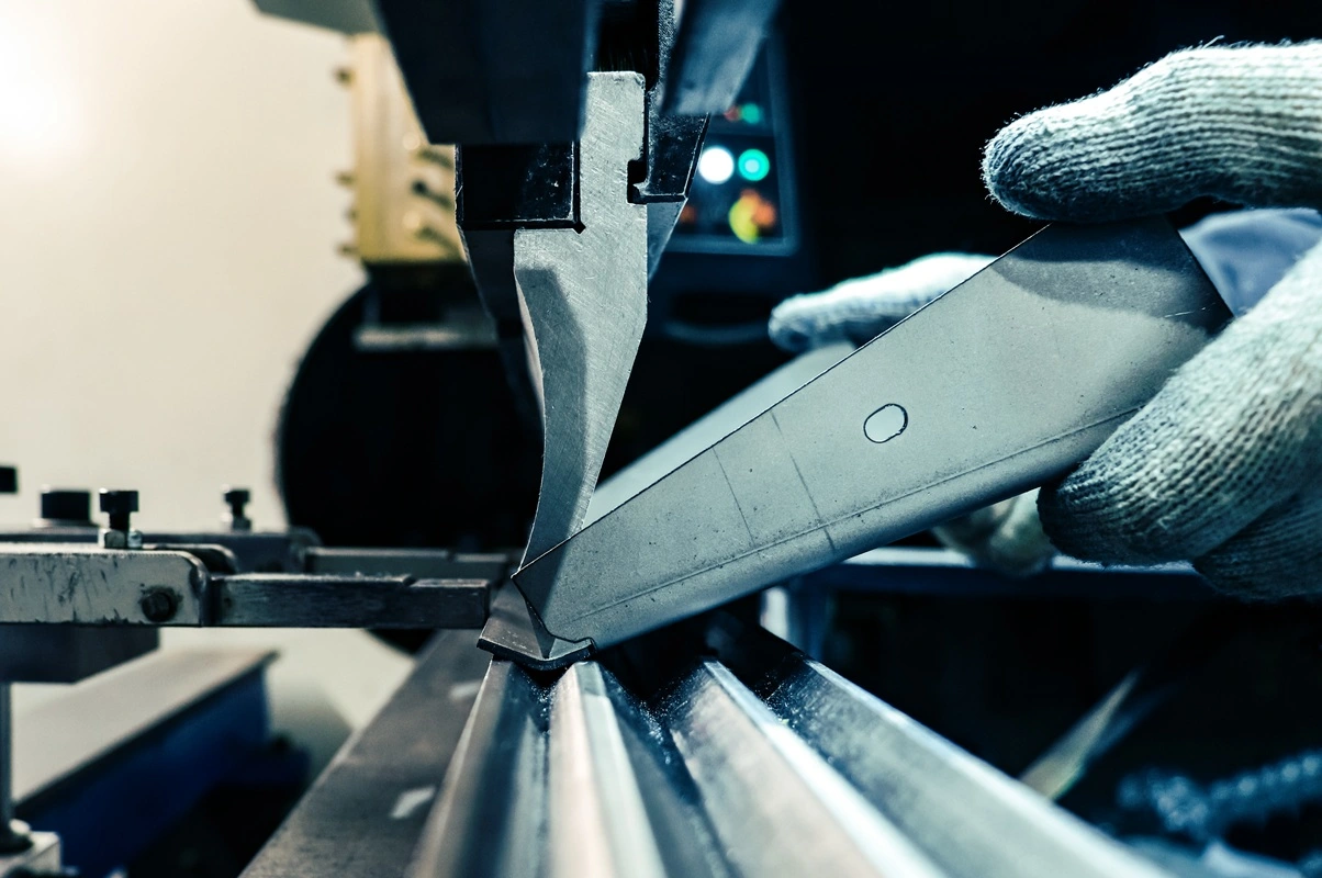
In air bending, the die opening strongly influences the radius formed in the sheet. WILA calls this the natural product radius and distinguishes it from the punch-tip radius, so a punch stamped with the CAD radius does not by itself set the finished radius. The material reference, the tooling, and the CAD model each describe the bend differently, and the released drawing has to agree with all three.
| Input | What it establishes | What it does not establish |
|---|---|---|
| Material forming reference | The minimum radius the material tolerates under stated conditions | The radius a given press-brake setup produces |
| Press-brake tooling | The natural radius the setup forms; a wider V-opening generally forms a larger one | Whether the material tolerates that radius |
| CAD K-factor | The assumed neutral-axis position used to calculate the flat pattern | Whether the material tolerates a tighter bend |
Changing the V-opening also changes bending force, minimum flange length, and the flat pattern, so the fabricator should review those effects together before approving a tooling change solely to reach a radius. Changing the K-factor in sheet metal alters a calculated flat length, not the physical bend, so confirm the physical radius before treating the CAD unfold rule as a production reference.
What Changes When You Increase the Bend Radius?
A larger radius reduces bend strain but enlarges the curved region and changes how the bend relates to nearby surfaces. In an ideal 2 mm bracket whose inside radius increases from 2 mm to 4 mm, the outside radius increases from 4 mm to 6 mm at constant thickness. If a mating part occupies that corner, the changed curve needs a clearance check, and the design engineer decides which face or envelope stays fixed while the bend geometry changes.
The developed blank changes too. WILA notes that a change in V-opening changes the product radius and affects the flat pattern, so an earlier cut file can leave the blank inconsistent with the formed geometry. For sheet metal bending in brackets and panels, the mounting faces, formed hole locations, and envelope stay as the design targets; a larger radius is an option when the material reference or tooling calls for it and the revised geometry still meets those targets. Recheck a proposed radius change in this sequence:
- Confirm the new radius against the material reference for the specified alloy, condition, and thickness.
- Have the fabricator confirm the natural radius the proposed tooling produces.
- Check clearance at the mounting faces, formed hole locations, and envelope.
- Update the flat pattern to match the confirmed radius and tooling.
Get the Bend Reviewed With the Full Fabrication Route
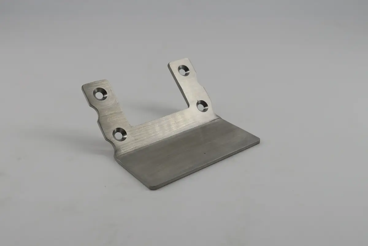
Send the radius for review together with the formed model, material specification, and critical dimensions. The fabricator then has a defined part to manufacture, and the design engineer has a clear basis for accepting or rejecting a proposed change.
Engineering and DFM Review
Rollyu Precision provides engineering and design for manufacturability (DFM) review for custom manufacturing projects, including sheet metal parts, and its sheet metal workflow includes material inspection, laser cutting, bending and forming, welding, deburring, surface finishing, and dimensional checks.
For a tight-radius bracket or enclosure, the review covers the specified alloy and condition, sheet thickness, target inside radius, and the formed dimensions that govern fit. If the fabricator proposes a different radius, compare it against the assembly model before release; the drawing remains the basis for the accepted geometry.
Cutting, Bending, and Finishing
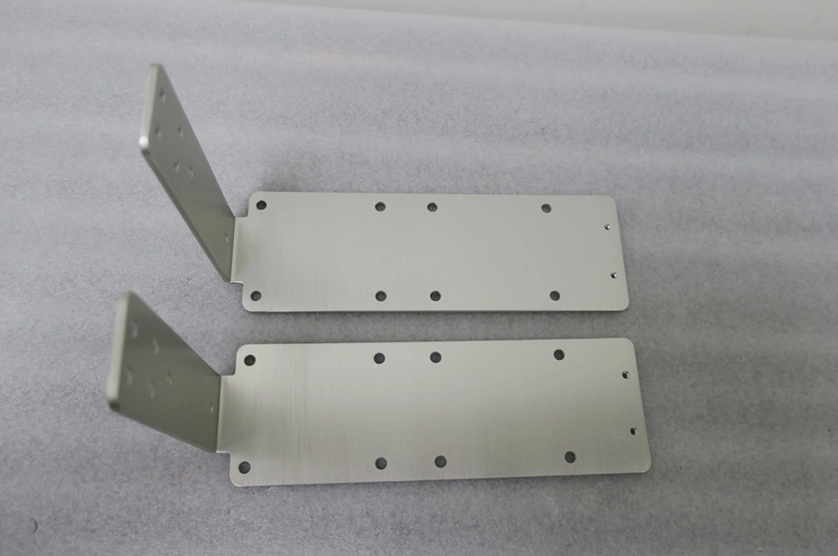
A formed enclosure may need welded seams, deburred edges, or a finished exterior in addition to accurate bends, so include those operations in the manufacturing discussion. Rollyu Precision’s sheet metal fabrication capabilities cover laser cutting, press-brake bending of stainless steel and aluminum, deburring, and TIG, MIG, and spot welding, with finishing options that include anodizing, powder coating, and polishing. The company supports sheet metal prototyping and low-volume production, so state sample and repeat-order requirements, along with a finish suited to the selected material and geometry, in the project review.
Prepainted aluminum needs separate attention. The Aluminum Association notes that prepainted sheet may need a larger radius to protect the paint, so identify an existing coating before bend review; a reference for uncoated stock does not settle the coating’s forming limit.
Inspection and Drawing Handoff
Dimensional checks in Rollyu’s workflow use digital calipers and coordinate measuring machines (CMMs). When a radius controls mating clearance, mark that clearance on the drawing, give the radius a tolerance, and agree on the inspection method. The quote package needs the formed 3D model and a 2D drawing that states the alloy and temper, thickness, inside radius, bend angle, critical formed dimensions, quantity, and finish; ask Rollyu to review the fabrication route against those requirements before approving a radius or material substitution.
Frequently Asked Questions
Does a Larger Bend Radius Reduce Springback?
Not for steel: a larger bend radius can increase springback. SSAB’s bending guidance links a smaller radius with less springback, and yield strength and die width also affect the result. Overbending compensates for elastic recovery. Keep that compensation separate from the minimum-radius check, since tightening the radius to correct the angle can increase forming strain.
How Do You Check the Inside Radius on a Finished Part?
Use a radius gage for an accessible inside curve, checking the curve against a known radius. Starrett shows convex gaging surfaces used against concave internal radii, including a 90-degree arc. For a controlled drawing dimension, agree on the inspection method and acceptance criterion with the fabricator.
Can You Use a Standard Bend-Radius Chart for a Hem?
No. A hem is pre-bent and then flattened, so a conventional bend-radius reference does not establish the full forming requirement; use hemming-specific guidance instead. WILA identifies the initial bend and the flattening stroke as separate parts of the operation. Confirm the material, flange geometry, and hemming tooling for that route.