
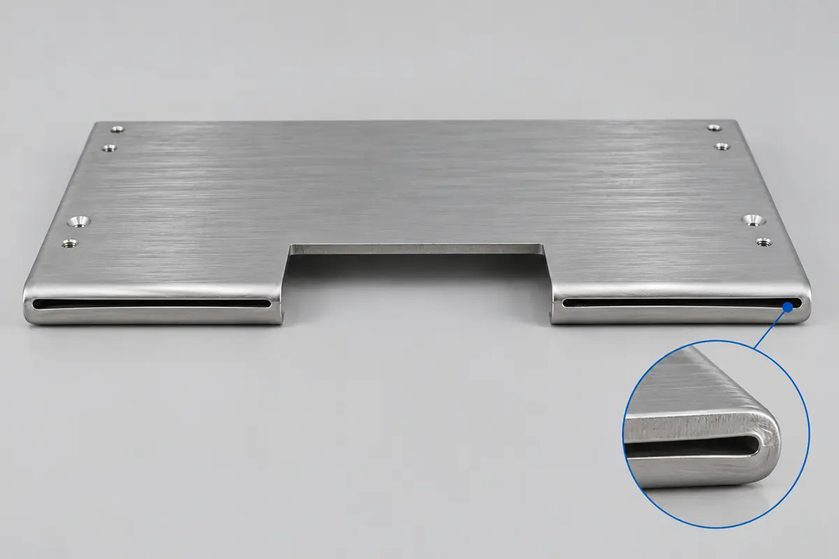

Sheet metal hemming folds an edge back onto the sheet to create a reinforced, finished border. Choose the hem type by what the edge has to do, then size its geometry for the material and the forming setup. On panels, covers, and enclosures, a compact flattened hem and an open rounded hem take up different space and place different demands on the design, so check the profile against the part’s interfaces and appearance.
How the Hemming Process Shapes the Edge
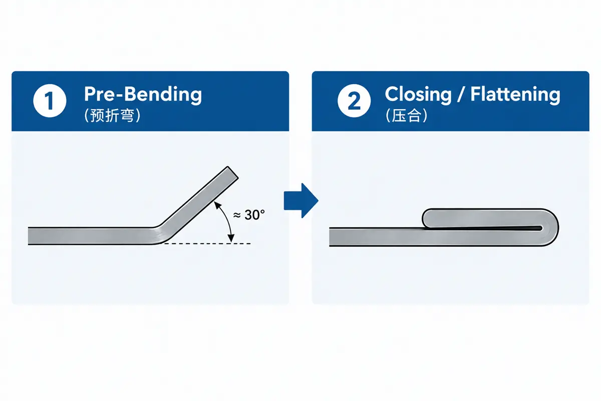
Press-brake hemming usually takes two steps: a pre-bend, then a closing stroke. The pre-bend forms the hem flange, or return flange, angled back toward the main sheet, and the closing stroke brings it to the specified profile. WILA’s hemming guidance describes a 30-degree pre-bend followed by flattening, and names the pre-bend radius and closing-stroke depth as factors in a finished open hem. So the final gap depends on the forming setup, not only on the shape drawn in CAD.
Hemming dies can combine both steps in one setup. Wilson Tool, for example, shows a gapped hem made in two hits with a single punch-and-die set. Either way, the hem needs a defined cross-section and suitable tooling before the flat pattern goes to production.
Which Sheet Metal Hem Types Fit Your Design?
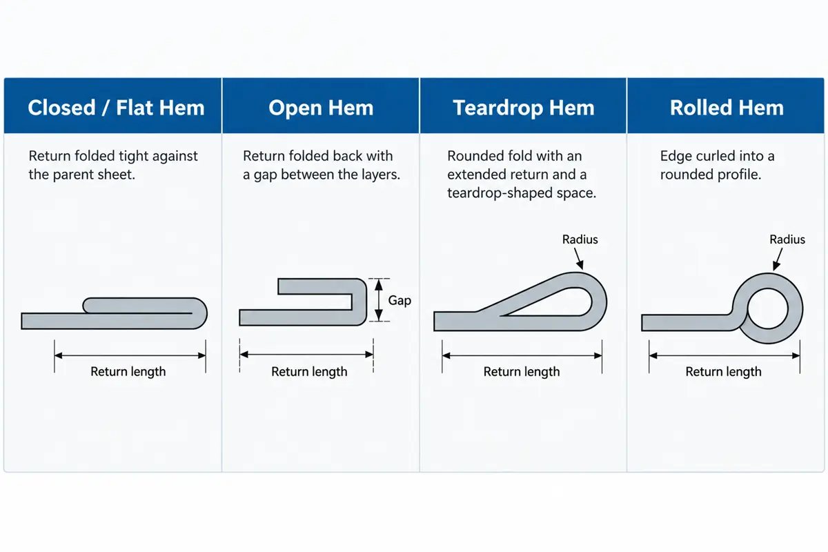
Choose a hem profile by the space the finished edge can occupy and the shape the part needs. Closed, open, teardrop, and rolled hems describe cross-sections. None of them sets a material limit or confirms that a fabricator can produce it.
| Hem Type | Finished Profile | Reason to Consider It | Geometry to Resolve |
|---|---|---|---|
| Closed or flat hem | Return folded tight against the parent sheet | Compact returned edge where no gap is needed | Return length, closing condition, and finished edge envelope |
| Open hem | Return folded back with a gap between the layers | Returned edge that keeps a specified opening | Clear gap, return length, and outside thickness |
| Teardrop hem | Rounded fold with an extended return and a teardrop-shaped space | Curved return where a fully flattened profile won’t work | Fold radius, return position, and remaining opening |
| Rolled hem | Edge curled into a rounded profile | Rounded border for a grip or other defined edge function | Radius, roll angle, and the space the curl occupies |
The closed-versus-open choice matters most on covers and panels. If the return faces the inside of an enclosure, include its full thickness and any opening in the clearance check, because an edge that looks compact from outside still takes up space behind the panel. Teardrop and rolled hems add a curved envelope that needs the same check against the adjoining part. CAD systems name and control hems differently, so put a section view on the drawing to show the intended profile.
Design the Hem Around Material and Geometry
Define the sheet and the finished cross-section together. Material, return length, gap, and radius form one forming problem, and changing any one of them can reopen the others.
Material Grade, Condition, and Thickness
Specify the alloy and supplied condition, not just “aluminum” or “stainless steel.” Wilson Tool’s aluminum-forming guidance makes the point directly: a grade and temper such as 5052-H32 tells the tooling specialist what the word “aluminum” can’t. Keep sheet metal bend radius guidance separate from the hem’s closing conditions. A conventional bend reference covers a different geometry from a return that gets flattened afterward, so approving a material for an ordinary bend doesn’t approve it for the hem. Give the fabricator the sheet thickness and the exact hem profile along with the material.
Return Length, Gap, and Radius
The return has to be long enough for the pre-bend. WILA ties the shortest possible hem to the minimum flange length its tooling can pre-bend, so set the return length against the tooling that will form it. On the drawing, dimension each element on its own:
- Return length: measured from a stated reference and kept distinct from the hem’s total width in the flat blank. Have the fabricator confirm the hem allowance used to develop that blank.
- Gap: for an open hem, the clear distance between the facing layers.
- Radius and angle: for rolled and teardrop profiles, the values that define the curve.
Autodesk Inventor’s hem feature, for example, takes gap, length, radius, and angle as separate inputs. In the layout, check both the folded return and the outside curve, since the return can clear a nearby component while the curved edge still projects into its space.
Corners and Nearby Features
Where two hemmed edges meet at an enclosure corner, they need room to close. SOLIDWORKS handles this with a miter-gap setting for intersecting hems plus separate relief controls: the miter gap sets the space between neighboring hems, and the relief settings define the cuts around the forming region. Where a return stops at or runs close to another bend, review the sheet metal bend relief as well. Check the corner opening in the formed model, then trace the cut boundary in the flat pattern and watch how much material remains around mounting holes and seating surfaces. A corner that clears both returns still has to preserve the interfaces the part depends on.
Plan Tool Access and the Finished Surface
A workable hem profile still needs a forming sequence the equipment can reach. On a visible panel or cover, surface appearance adds a second constraint.
Forming Sequence and Tool Clearance
Check the part at every forming stage, including the shapes it takes before the final bend. An enclosure wall can hit the punch, tool holder, or machine even when the finished CAD model shows no interference. WILA’s box-bending guidance lists machine open height, tooling height, and punch profile as checks, and return flanges add to the clearance needed behind the punch. Ask the fabricator when the hem gets formed relative to the other walls, and base that sequence on the actual tooling. A model that folds cleanly on screen tells you nothing about machine clearance.
Visible Surfaces and Finishing
Treat tool marking as a design input on cosmetic edges. WILA warns that hemming marks the sheet and damages protective foil in the operation it describes, so protective film alone can’t support a promise of an unmarked visible edge. Identify the exposed face and the acceptable appearance before the forming method is settled, and review sheet metal finishing at the same time so material, surface treatment, and cosmetic requirements are decided together. For a visible cover, a representative sample gives engineering and sourcing a real surface to approve before repeat orders.
Bring the Complete Part to Rollyu Precision
Review the hem as part of the whole panel or enclosure. Rollyu Precision supports that review with engineering, cutting, bending, joining, finishing, and inspection capabilities.
Engineering and DFM Review
Rollyu Precision provides engineering and design for manufacturability (DFM) review for custom parts, and its sheet metal workflow starts with that review and material inspection before laser cutting and forming. Bring the proposed hem in while its profile and the surrounding geometry can still change, along with:
- The formed 3D model and a dimensioned drawing showing the hem cross-section
- Material grade, condition, thickness, and intended finish
- Mounting interfaces, clearance limits, and visible surfaces that control the design
- Prototype quantity and expected repeat-order quantity
Ask Rollyu Precision to confirm the proposed hem type and forming method for that part.
Fabrication and Finishing
For custom panels and enclosures, Rollyu Precision’s sheet metal fabrication covers laser cutting, press-brake bending of stainless steel and aluminum, TIG, MIG, and spot welding, and deburring. Finishing options include anodizing, powder coating, and polishing, and the company supports sheet metal prototypes and low-volume production. On a hemmed cover or enclosure, keep these operations in the same review by stating which edges get returned, which seams get joined, and which faces stay visible.
Inspection and Drawing Handoff
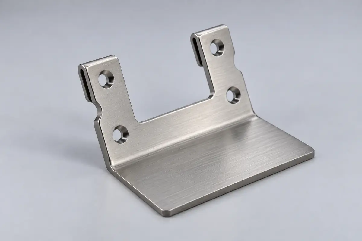
Rollyu Precision’s sheet metal workflow includes digital-caliper measurement and CMM testing. Measuring equipment doesn’t define a hem tolerance or acceptance criterion, though, so use the drawing to identify the finished dimensions and interfaces that matter and agree on how each one will be inspected.
Send the panel or enclosure model with its proposed edge section, material, finish, and quantity. Request a DFM review that covers hem feasibility, the surrounding fabrication steps, and the dimensions to verify on the finished part.
Frequently Asked Questions
Is a Rolled Hem the Same as Roller Hemming?
No. A rolled hem is a finished edge profile, while roller hemming is a forming method in which a roller travels along a flange and folds it progressively. ABB’s robotic hemming systems use this method to fold outer flanges over inner panels. Specify the final cross-section separately from the proposed forming method.
Can Hemming Join Two Sheet Metal Parts?
Yes. Hemming can fold the edge of one panel over another to form a joint, as in ABB’s body-in-white joining applications. That joint is a different design task from returning a single sheet edge, so define the mating panel and joint requirements separately and confirm the joining scope with the manufacturer.
Can You Make Another Bend Through a Hemmed Area?
Yes, with a suitable setup. WILA notes that bending inside a hem requires tooling adjustments because the folded area is double the sheet thickness. Flag that later bend during manufacturing review so the fabricator checks the layered section and the forming sequence together.