
A press fit holds two parts with interference alone, the few microns by which a shaft is machined larger than its bore. ISO 286 and ASME B4.1 sort that interference into named fit classes. Too much splits the hub. Too little lets the joint slip.
Press fit tolerance controls that margin. It sets a minimum interference that still carries the load and a maximum the materials survive. This guide covers the fit classes and charts, what changes the interference you need, and how to choose, specify, machine, and verify the joint.
What Press Fit Tolerance Means
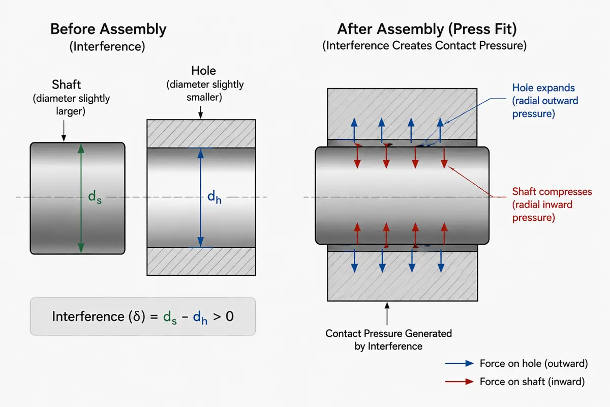
Press fit tolerance is the controlled band of interference between a shaft and a hole, where the shaft measures slightly larger than the bore. When the parts meet, the bore pushes out and the shaft squeezes in, and the radial pressure from that elastic deformation grips them by friction, with no key, pin, or fastener. A clearance fit leaves a gap, a transition fit lands near zero, and a press fit always keeps the shaft larger than the bore.
Press Fit Tolerance Classes and Charts
Press fits are named by standard fit classes that each set the interference. ISO 286 covers metric, ASME B4.1 covers inch, and the charts below give real values to size from.
Minimum and maximum interference in the tolerance band
A press fit specifies a range of interference, not one number, because both the shaft and the hole carry tolerance. The smallest shaft in the largest hole gives the minimum interference, which must hold the load. The largest shaft in the smallest hole gives the maximum interference, which the hub must survive. A safe fit keeps the whole band between those limits.
ISO 286 hole-basis interference fits
ISO 286 holds the bore to a fixed tolerance, usually H7, and changes the shaft to set the interference. Three shaft grades cover most work: p6 for light press fits, s6 for medium drive fits, and u6 for heavy force or shrink fits. The table gives the interference at three shaft diameters.
| Fit (ISO 286) | Level | Interference at Ø10 mm | Interference at Ø25 mm | Interference at Ø50 mm | Typical use |
|---|---|---|---|---|---|
| H7/p6 | Light | 0.000 to 0.024 mm | 0.001 to 0.035 mm | 0.001 to 0.042 mm | Locational interference, dowel and locating pins |
| H7/s6 | Medium | 0.008 to 0.032 mm | 0.014 to 0.048 mm | 0.018 to 0.059 mm | Drive or press fit, plain bushings, gear and pulley hubs |
| H7/u6 | Heavy | 0.013 to 0.037 mm | 0.027 to 0.061 mm | 0.045 to 0.086 mm | Force or shrink fit, high-torque hubs |
One step lighter, H7/n6 is a transition fit that can land slightly loose or tight, for parts that locate accurately but may come apart. Rolling bearing seats are a special case: they follow the bearing maker’s recommended fits, usually lighter than s6, so size them from the catalog.
ANSI and ASME FN force-fit classes
In the inch system, ASME B4.1 names press fits as force and shrink fits, FN1 through FN5.
- FN1 Light drive fit
- FN2 Medium drive fit
- FN3 Heavy drive fit
- FN4 Force fit
- FN5 Heavy force and shrink fit
ISO 286 and the FN system use different bands and formulas, so they do not map one to one. Pick one system per drawing.
What Determines the Right Interference
The right interference is not fixed. It shifts with five variables.
- Shaft diameter: Interference grows with diameter in stepped bands, so a 50 mm s6 shaft carries far more than a 10 mm one.
- Material stiffness and yield: Steel builds holding pressure fast and takes more interference. Aluminum and brass yield sooner and can deform.
- Hub wall thickness: A thin wall acts like a ring under pressure and can split. Thicker walls take more interference.
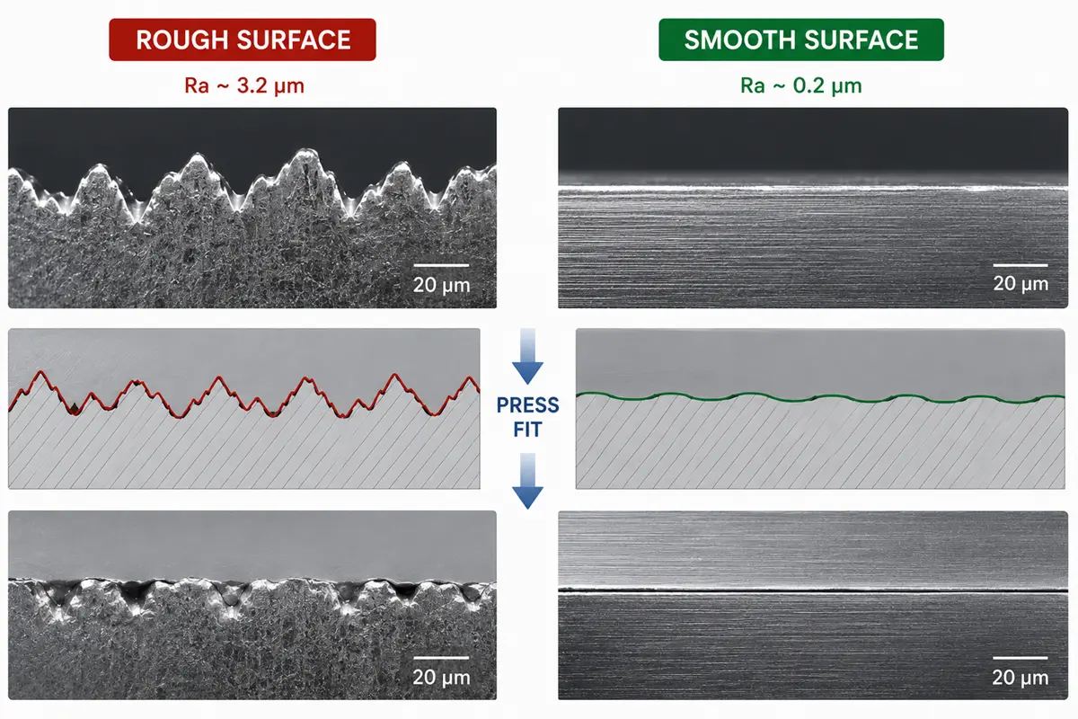
- Surface finish: Pressing flattens the surface peaks, so a rough bore loses interference. Aim near Ra 0.8 µm or below on the mating face.
- Operating temperature: Heat expands the parts and changes the interference, most when the shaft and hub are different metals.
How to Choose the Right Press Fit Tolerance
Choosing a fit balances two demands: enough interference to hold the load, not so much that the hub fails. Work from the joint’s duty, then check it against the material and geometry.
Calculating interference from load and stress limits
Size from the load, then check the stress. The minimum interference must generate enough contact pressure and friction to carry the axial force or torque. The maximum must stay below the point where the hub yields or the shaft galls. Engineers run this with the thick-wall cylinder equations (Lamé’s equations) or finite element analysis. For routine parts, a standard fit class already lands safe; for high-load, thin-wall, or brittle parts, run the numbers.
Matching the fit class to the function
Pick the fit from what the joint does, then confirm it against the material and hub geometry.
| Function | Suggested fit |
|---|---|
| Accurate location, must stay removable | Transition, H7/k6 or H7/n6 |
| Light permanent location, low load | H7/p6 |
| Torque or axial load, semi-permanent | H7/s6 |
| Heavy load or thermal shrink assembly | H7/u6 |
These fits run through precision assemblies. Bearing carriers, gear hubs, and dowel pins in robotics CNC machining pair a located shaft with a pressed hub, where the fit class decides whether the part holds under cyclic motion.
How to Specify Press Fit Tolerance on a Drawing
A press fit only works if the drawing states it cleanly. Two things control how the shop machines it: the basis system, and how you call out the limits and form.
Choosing hole-basis or shaft-basis systems
Most shops work hole basis: the bore stays at a standard H7 limit and the shaft changes to set the fit, because a reamed bore is harder to adjust than a shaft. Shaft basis flips that for parts built around a fixed shaft like a ground dowel. Pick one and keep the drawing consistent.
Calling out limit dimensions and GD&T cylindricity
Specify the fit two ways: name the ISO class directly, such as Ø20 H7/s6, or list the bore and shaft limit dimensions. Add the surface finish on both mating faces, since it changes the working interference, and control cylindricity with a GD&T callout where it matters, because an out-of-round bore presses with less than the calculated interference.
For custom CNC machining parts, fix the fit class, the limit dimensions, the mating-face finish, and any cylindricity tolerance before the part goes out for quote.
How to Machine and Assemble a Press Fit
Making a press fit means cutting both parts to size, checking them, and joining them in order. The bore leads, the shaft is cut to match it, and assembly is the one step nothing can fix.
Boring and reaming the bore
The bore sets the baseline, so it gets machined first and held tight. Boring brings the hole to size and corrects drilling drift, then a reaming or finish pass holds the H7 limit and the round, straight form the fit needs. Precision boring controls diameter and cylindricity better than drilling on deep or large bores.
Turning and grinding the shaft
The shaft carries the interference, so it gets cut to match the bore just measured. Turning reaches the p6 or s6 range on most materials; grinding takes over for a tighter band, a harder material, or a finer finish. Measuring the bore first, then sizing the shaft to it, keeps the interference on target instead of stacking two tolerances.
Verifying the parts before assembly
Check both parts at temperature before they meet, because a press fit cannot be reworked once together. Bore gauges and plug gauges read the hole, micrometers read the shaft, and a CMM confirms diameter and roundness on critical parts. Rollyu Precision CNC machining holds mating bores and shafts down to ±0.005 mm on precision features and verifies critical dimensions with CMM and gauge checks under an ISO 9001 and ISO 13485 certified workflow before parts reach assembly.
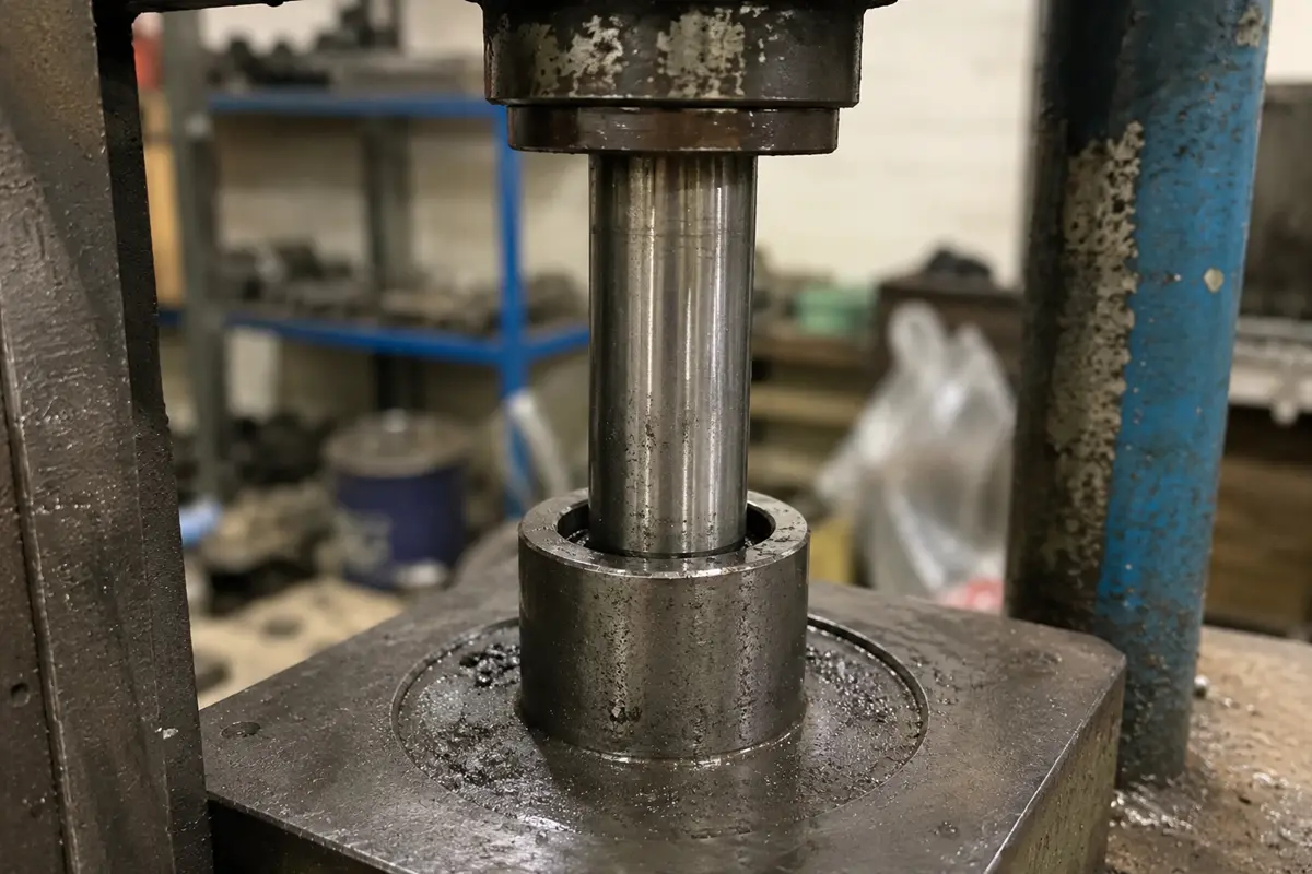
Pressing and thermal fitting
Assemble by force or by temperature. A cold press drives the shaft in with an arbor or hydraulic press for small to medium interference, with lubricant and a steady speed to avoid galling. For large or heavy interference, use thermal fitting: heat the hub to expand the bore, or chill the shaft to shrink it, join the parts, then let them lock as they return to temperature.
Common Press Fit Failures and How to Avoid Them
Most press fit problems trace to assembly damage, material behavior over time, or service loads, not the sizing. Three failure modes cover the majority.
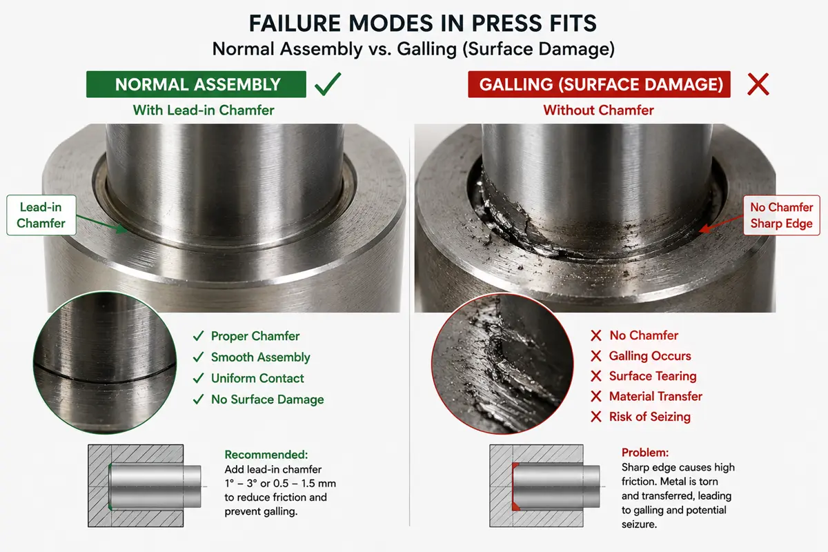
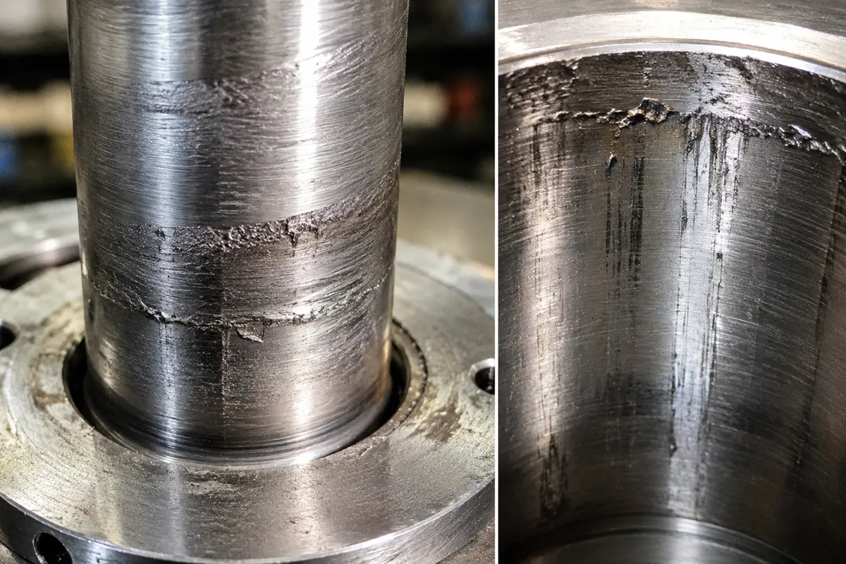
Galling and scoring during pressing
Galling tears metal off the shaft or bore as it presses in, scoring the surfaces and jamming the assembly. It hits hardest with heavy interference, dry surfaces, or galling-prone metals like stainless and aluminum. A lead-in chamfer lets the parts start square, and lubricant with a steady press speed keeps the surfaces from welding. For heavy interference, switch to thermal fitting.
Loosening from stress relaxation and creep
Interference fades when the material relaxes under sustained stress. Plastics and soft metals creep most, so a fit that felt tight at assembly can slacken after weeks under load or heat. Choose a fit that still holds after some relaxation, or back it up with a key, pin, or retaining compound on parts that must stay tight for years.
Fretting at the mating interface
Fretting wears the contact face under vibration or cyclic load, even with the parts pressed together. Small repeated movements rub the surfaces, shed debris, and can start fatigue cracks at the edge of the fit. More interference, a smoother finish, and a fillet at the hub edge all cut fretting.
FAQs
Is a press fit the same as an interference fit?
Mostly yes. A press fit is one kind of interference fit, the family where the shaft is larger than the bore. The name points to how the parts join, by pressing, while a shrink fit reaches the same interference with heat. Every press fit is an interference fit, but not every interference fit is pressed.
Can you press fit aluminum into steel?
Yes, but plan for the temperature swing. Aluminum expands about twice as much as steel, so an aluminum hub on a steel shaft loosens when hot and tightens when cold. Size the interference for the hottest service temperature, and check the cold condition does not overstress the aluminum. For wide ranges, add a key or retaining compound.
Can you press fit into a plastic part?
Yes, with lighter interference and a wider tolerance. Plastics have far lower stiffness than metal, so they need less interference and crack more easily when it is too much. They also creep, so a plastic press fit relaxes over time. Use a generous lead-in, keep the interference modest, and design for the relaxed state.
Can a press fit be disassembled and reused?
It can be pressed apart, but reuse weakens the joint. Pulling the shaft out scores both surfaces and flattens the high spots that carried the interference, so it grips with less force the second time. For parts that come apart often, use a transition fit or a fastener instead.
Should you use a retaining compound with a press fit?
It depends on the load and the margin. A correctly sized press fit holds on its own, but an anaerobic retaining compound fills the surface valleys, adds shear strength, and seals against fretting and corrosion. It earns its place on lighter fits, parts that vibrate, or a slightly loose interference. On a heavy fit, it is optional insurance.