Casting shrinkage risk drops when engineers review wall thickness, hot spots, gate flow, and critical machined features before tooling. Die-cast walls should stay as consistent as possible, with transitions added where the design needs wall changes. That design rule matters because uneven cooling can leave shrinkage porosity, sink marks, weak bosses, warped datums, and late-stage scrap.
This guide explains how casting shrinkage happens, how shrinkage porosity differs from gas porosity, and how engineers reduce part risk before a die-cast part reaches machining, inspection, and assembly.
What Is Casting Shrinkage?
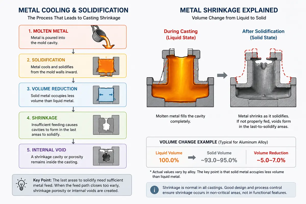
Casting shrinkage is the volume change that happens as molten metal cools and solidifies inside a mold or die. This volume change is normal in metal casting, but poor part geometry or process control can move shrinkage into functional areas instead of non-critical zones.
In die casting, shrinkage risk matters most around thick bosses, heavy pads, sealing faces, bearing seats, and threaded holes. These areas often carry load, hold fasteners, seal fluids, or locate another part. If shrinkage creates a void near one of these features, the casting may pass a quick visual check but fail after machining, leak testing, or assembly.
The die casting process uses high pressure to drive molten metal into a die, which is why this process fits complex metal parts at production volumes.
Why Does Casting Shrinkage Happen?
Casting shrinkage happens when the casting loses volume during cooling and the last areas to solidify do not receive enough metal support. Geometry, wall thickness, gate layout, die temperature, fill behavior, and alloy choice all affect where shrinkage appears.
Solidification Volume Loss
Molten metal occupies more volume than solid metal. As the metal freezes, the solid skin forms first and the remaining liquid metal must feed the last areas to solidify. When the feed path closes too early, a cavity or fine shrinkage porosity can form inside the casting.
This defect often hides below the surface. A part can look acceptable after trimming, then show pores after drilling, tapping, milling, or pressure testing.
Thick Sections and Hot Spots
Thick sections cool slower than nearby thin walls. These slow-cooling areas become hot spots, especially near bosses, pads, rib intersections, and heavy mounting blocks. A hot spot can pull liquid metal from nearby areas, leaving sink marks on the surface or shrinkage porosity inside the thicker section.
This issue becomes more expensive in cast aluminum housings or brackets when the thick section also carries a machined feature. A threaded boss with hidden porosity may reject the part only after casting, trimming, deburring, and machining are complete.
Uneven Wall Thickness
Uneven wall thickness makes cooling less predictable. Wall thickness has no one-size rule in die casting, but wall sections should stay consistent where possible and use transitions where the geometry needs changes.
Sudden wall jumps, thick-to-thin intersections, and isolated material masses can shift shrinkage into areas that need strength, sealing, or cosmetic quality.
Poor Gate, Runner, and Overflow Design
Gate, runner, and overflow design affects how metal fills the die and where pressure can support the casting during solidification. A poor layout can leave turbulence, weak feed paths, cold areas, or isolated hot spots that raise porosity and shrinkage risk.
Die casting does not use classic sand-casting risers in the same way. The die-casting fix usually depends on gate location, runner balance, overflows, venting, local pressure transfer, and thermal balance across the die.
What Is the Difference Between Shrinkage Porosity and Gas Porosity?
Shrinkage porosity comes from solidification volume loss, while gas porosity comes from trapped or dissolved gas. The visible result may look similar, but the fix changes because one defect points to feeding and cooling, while the other points to air, turbulence, melt quality, or venting.
Shrinkage Porosity
Shrinkage porosity forms when the last liquid metal cannot feed a shrinking area during solidification. This defect often appears near hot spots, thick bosses, heavy pads, or sections where wall thickness changes too quickly.
Engineers usually review wall transitions, local mass, gate flow, overflow position, die temperature, and whether critical features sit too close to risky solidification zones.
Gas Porosity
Gas porosity forms when air or dissolved gas becomes trapped in the casting. High fill speed, turbulence, poor venting, moisture, lubricant problems, or melt quality can all increase gas-related pores.
In cold chamber die casting, a plunger drives molten metal into a locked die at high pressure. That pressure helps fill complex shapes, but fill speed and venting still need control because trapped air can create internal pores.
Why the Defect Type Changes the Fix
The wrong diagnosis wastes toolroom time. Shrinkage porosity may need wall changes, overflow changes, local cooling changes, or feature relocation. Gas porosity may need venting, shot control, melt handling, vacuum support, or lubricant review.
For high-pressure parts, both defect types may need inspection beyond visual review. Sectioning, X-ray, CT, leak testing, or machining trials can show whether the void pattern matches shrinkage, gas, or a mixed issue.
What Defects Does Casting Shrinkage Create?
Casting shrinkage creates surface defects, hidden internal voids, and machining problems that may not appear until later operations. The highest buyer risk is late discovery, because the part has already consumed tooling, casting, trimming, machining, finishing, and inspection time.
| Defect | Where It Usually Appears | Buyer Risk | Review Point |
|---|---|---|---|
| Sink marks | Thick walls, bosses, ribs, and pads | Cosmetic rejection or uneven mating faces | Wall thickness and local mass |
| Internal cavities | Last areas to solidify | Strength loss or leak paths | Hot spots and pressure support |
| Weak bosses | Threaded holes, bearing fits, and mounting points | Weak threads or poor assembly fit | Boss design and machining depth |
| Datum shift | Flat faces, hole patterns, and locating surfaces | Assembly mismatch | Cooling balance and final inspection |
| Machined-through voids | Bores, tapped holes, and sealing faces | Scrap after added machining cost | Machining stock and inspection method |
Sink Marks
Sink marks are shallow depressions that often appear over thick sections, bosses, ribs, or pads. These marks form when the outer surface pulls inward as the internal mass cools and shrinks.
Cosmetic sinks may be acceptable on a hidden face, but sink marks near a sealing face, visible cover, or mounting pad can create fit, finish, or customer approval problems.
Internal Cavities
Internal cavities often form in the last areas to solidify, especially where heavy material traps heat and cannot receive enough metal support.
Casting skin can hide an internal cavity until machining opens the section or pressure testing finds a leak path.
Weak Bosses and Thick Sections
Bosses and thick sections often combine high local mass with later machining needs. A boss may need drilling, tapping, reaming, or a bearing fit, which means the casting must stay sound below the surface.
If shrinkage sits inside the boss, the machined thread can tear out, the bore can leak, or the fastener area can lose strength. The safer DFM move is to core heavy bosses, add ribs, blend transitions, and check machining depth before tooling.
Warping and Datum Shift
Warping happens when different areas cool and shrink at different rates. A casting may hold its general shape but lose flatness, hole position, or datum stability.
Datum shift is a serious assembly risk. A robot bracket, optical mount, or pump housing can fail fit checks even when the visible casting surface looks acceptable.
Voids Exposed After Machining
CNC work can expose shrinkage voids inside the casting. Drilling, boring, milling, tapping, and facing remove the sound outer skin and may cut into a porous area.
This failure mode is painful because the defect appears after the supplier has added value. Engineers should plan machining stock around casting soundness instead of using extra stock as a blanket fix for every risky feature.
How Can Engineers Reduce Casting Shrinkage Risk?
Engineers reduce casting shrinkage risk by controlling local mass, wall transitions, fill behavior, thermal balance, and critical feature placement before tooling. Early DFM review usually costs less than die rework, sample rejection, or late machining scrap.
Keep Wall Thickness Consistent
Uniform wall thickness helps the casting cool in a more predictable pattern and reduces abrupt thermal changes.
The goal is not one thickness everywhere. The goal is a stable cooling path with controlled transitions where strength, fastening, or sealing needs extra material.
Avoid Heavy Isolated Sections
Heavy isolated sections create hot spots. These areas cool later than nearby walls and can become the first place shrinkage porosity appears.
Common high-risk areas include large bosses, thick pads, heavy mounting blocks, and rib clusters. If the design needs strength, ribs or cored sections often control mass better than one solid block of metal.
Use Ribs, Cores, and Gradual Transitions
Ribs, cores, and gradual transitions can add stiffness without trapping too much heat in one area, which helps reduce sink marks, internal cavities, and warped datums.
A cored boss can still support a screw or locating feature when the boss wall has enough support. A gradual transition can also protect the nearby thin wall from pulling or sinking during cooling.
Balance Fill, Venting, and Die Temperature
Engineers should review fill, venting, and die temperature together. Fast filling can support thin features, but poor venting can trap air. A cold die can freeze metal too early, while an overheated local zone can hold liquid metal too long and create a shrinkage-prone hot spot.
Squeeze casting uses pressure during solidification to improve density and reduce gas entrapment. Standard high-pressure die casting is a different process, but the comparison shows why pressure, gas control, and flow stability matter when density is important.
Review Critical Features Before Tooling
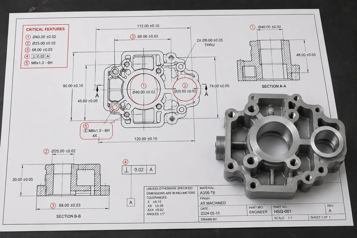
Buyers should mark critical features before the toolmaker builds the die. Sealing faces, threaded bosses, bearing seats, press-fit areas, datum planes, and leak paths need more review than cosmetic ribs or hidden covers.
This review should connect the casting plan to later operations. If the supplier will tap a hole after casting, the supplier should check boss mass, machining depth, thread engagement, and inspection method before producing samples.
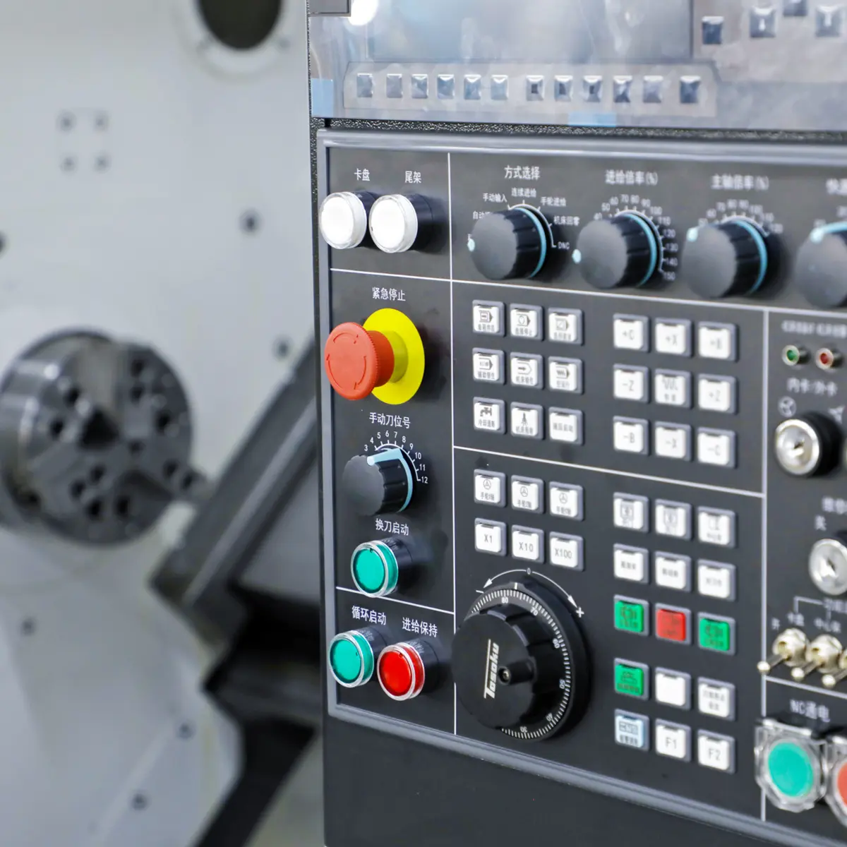
When Should Cast Parts Use Secondary CNC Machining?
Cast parts should use secondary CNC machining when the as-cast process cannot hold the feature accuracy, surface finish, or geometry needed for assembly. CNC machining improves functional surfaces, but CNC machining does not repair internal shrinkage porosity.
Machined Datums and Sealing Faces
Machined datums and sealing faces are common on die-cast housings, brackets, covers, and fluid-control parts. These surfaces often need tighter flatness, location, or finish than the casting surface should carry alone.
Secondary machining can cut the datum to size, but the casting underneath must be sound. If shrinkage sits below the surface, facing or boring may expose a void in the exact area that needs sealing.
Threaded Holes and Bearing Fits
Internally tapped holes usually need secondary machining instead of as-cast forming. Engineers should treat threaded holes, bearing fits, reamed holes, and precision bores as functional features from the first DFM review.
For cast parts that need threads or bearing seats, the supplier should confirm wall thickness, boss support, hole depth, machining allowance, and inspection requirements before tooling.
Machining Stock and Porosity Risk
Machining stock gives CNC tools material to clean up datums and critical surfaces. Too little stock can leave cast surface variation. Too much stock can cut deeper into a porous zone and expose shrinkage after the part has already consumed machining time.
Machining stock should be feature-specific. A sealing face, a tapped boss, and a cosmetic edge do not need the same allowance or the same inspection plan.
When CNC Machining Is Safer Than Casting
CNC machining is safer than casting when the part has low volume, thick solid geometry, deep machined pockets, tight datum relationships, or internal soundness requirements that make casting risk too high.
Buyers comparing casting vs machining should weigh tooling cost, volume, geometry, tolerance, and post-machining work before quoting.
How Should Buyers Check a Shrinkage-Sensitive Casting Supplier?
Buyers should check whether the supplier can review casting design, tool design, CNC machining, inspection, and documentation as one workflow. Shrinkage-sensitive parts fail when teams split these steps across separate reviews.
DFM Review Before Tooling
DFM review should happen before the toolmaker cuts tooling steel. The review should check wall thickness, thick bosses, rib intersections, gate and overflow strategy, venting, machining stock, critical features, and inspection needs.
For shrinkage-sensitive parts, the DFM discussion should name the failure mode directly. A supplier should explain where shrinkage or porosity is most likely to appear and how the design or process plan reduces that risk.
Die Casting and CNC Machining Capability
A supplier with both die casting and CNC machining support can review the casting body and the machined features together. This matters when threaded holes, bearing fits, sealing faces, or datum surfaces sit near thick sections.
For projects where cast geometry and machined features overlap, buyers should review die casting parts with the post-machining plan before production. The review should connect tooling, casting, CNC machining, finishing, dimensional inspection, and traceability before samples move forward.
Inspection Method Matching
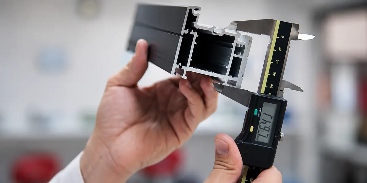
Inspection should match the failure risk. Visual inspection can catch sinks and visible surface defects. CMM inspection checks machined geometry. Leak testing checks pressure-tight parts. X-ray, CT, or sectioning may help when internal porosity affects sealing, strength, or customer approval.
For motion-control parts, robotics components often need stable datums, repeatable hole positions, and clean mounting faces. Shrinkage review should focus on the features that control motion, alignment, and assembly repeatability.
Documentation and Traceability Needs
Buyers should define documentation before approving the quote. Buyers may need dimensional reports, FAI support, material documentation, Certificates of Conformance, surface finish checks, or lot-level traceability.
Rollyu Precision supports DFM review, dimensional inspection, material traceability, FAI support, Certificates of Conformance, and lot-level traceability when the project requires documentation. These records matter when a shrinkage issue affects a later assembly, field return, or supplier approval process.
What Should Buyers Send for a Shrinkage Review?
Buyers should send a 3D model, 2D drawing, material requirement, annual volume, functional surfaces, testing needs, and finishing requirements for a shrinkage review. A screenshot is not enough when the part has sealing faces, threaded bosses, or precision datums.
- 3D CAD model: STEP, X_T, or another editable neutral file.
- 2D drawing: Tolerances, datums, threads, critical dimensions, and inspection notes.
- Material requirement: Aluminum alloy, zinc alloy, or approved equivalent.
- Expected volume: Prototype, pilot, or production quantity.
- Functional surfaces: Sealing faces, bearing fits, threaded holes, press-fit zones, and cosmetic faces.
- Testing needs: Leak testing, CMM report, FAI, material documentation, or surface finish inspection.
- Finishing needs: Deburring, polishing, plating, painting, powder coating, or anodizing when applicable.
The drawing should mark no-porosity zones and critical-to-function dimensions. Clear notes help the supplier focus design review and inspection on the areas where shrinkage would create the highest cost.
FAQs
Can a Die-Cast Part With Minor Porosity Still Be Usable?
Yes, minor porosity can be usable outside critical zones. Sealing faces, threaded bosses, bearing seats, pressure paths, and load-bearing areas need tighter review because small voids can create leaks, weak threads, poor fits, or assembly failure.
Should Buyers Mark No-Porosity Zones on a Casting Drawing?
Yes, buyers should mark no-porosity zones on the drawing. These notes tell the supplier which surfaces need extra DFM review, machining allowance control, and inspection. Without clear zones, cosmetic areas and functional areas may receive the same review depth.
Can Vacuum Impregnation Save a Porous Die Casting?
Vacuum impregnation can seal some connected porosity. This process forces sealant into connected pores, often after pressure testing finds nonconforming castings. This step can help pressure tightness, but impregnation does not replace sound design.
Are Die-Cast Parts Suitable for Pressure-Tight Applications?
Die-cast parts can support pressure-tight applications with the right design, alloy, process control, and testing. Buyers should state test pressure, fluid or gas medium, leak-rate limit, and inspection standard before tooling so the supplier can plan porosity control and verification.
Can Suppliers Weld or Heat Treat Die-Cast Parts After Production?
Welding and heat treatment need early supplier review. Internal porosity can expand under heat and create cracks, blisters, or surface damage. If the part needs welding or heat treatment, buyers should confirm the alloy, casting process, porosity level, and acceptance standard before tooling.