

Prevent plating defects by controlling the zinc casting, part geometry, pretreatment, coating stack, and inspection plan as one process. Plating cannot repair open porosity or poor geometry, and trapped process solution can stain or lift the deposit.
ASTM B252 ties coating performance to the cleanliness and condition of the zinc surface. Buyers should lock the finish requirements before tooling and approve production only after the plated first article passes appearance, thickness, adhesion, and fit checks.
What Causes Common Plating Defects on Zinc Die Cast Hardware?
Most plating defects trace to weak adhesion, an uneven substrate, poor current distribution, or trapped process chemistry. The defect location and the layer that failed help narrow the root cause.
Blistering and Peeling
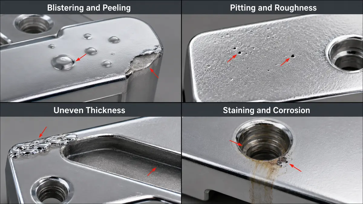
Blistering starts when the deposit loses adhesion to the zinc substrate or one plated layer separates from another. Die lubricant, oxide, polishing compound, and embedded abrasive can block bonding. Open pores, cold shuts, and cracks can retain process solution, which may later seep out or expand under heat.
Inspect where separation begins. Lifting at the zinc-to-undercoat interface suggests a casting or pretreatment problem. Separation between plated layers points to the plating sequence. A cross-section and an agreed adhesion test provide better evidence than appearance alone.
Pitting and Surface Roughness
Pits and roughness usually expose defects that existed before plating. Open pores, flow marks, gate trim damage, buffing scratches, and embedded media remain visible through the deposit. Bright nickel or chromium can make small waves and pits easier to see.
Copper can level minor surface texture within a qualified plating system. It cannot restore a porous casting. When pitting repeats in the same area, trace the causes of casting shrinkage and porosity before adding more copper.
Uneven Plating Thickness
Electroplating deposits more metal on edges, corners, ribs, and projections because those areas receive higher current density. Deep recesses, blind holes, grooves, and inside corners receive less. A part can therefore meet an average thickness target while a recessed surface remains below the required minimum.
Mark significant surfaces and measurement points on the drawing. Specify minimum local thickness at surfaces exposed to wear or corrosion. Do not rely on one average value.
Staining and Corrosion
Staining often starts when cleaners, plating solution, or rinse water remain in blind holes, threads, cup-shaped features, or seams. Residue can seep out after drying. Poor rinsing, incomplete drying, handling contamination, and a discontinuous deposit can produce similar marks.
Corrosion can start where the deposit is thin, damaged during assembly, or absent from a masked area. Record the defect location, color, and time of appearance. Then compare those details with rack orientation, drainage, masking, and thickness records.
What Should Buyers Specify Before Tooling Begins?
Freeze the service, appearance, coating, masking, fit, and inspection requirements before tooling. These decisions affect alloy choice, gate location, polishing access, rack orientation, and feature geometry.
Service and Corrosion Requirements
Define the service environment before choosing the coating stack. Put these requirements on the drawing or purchase order:
- Expected exposure, including humidity, weather, salt, cleaning chemicals, skin contact, abrasion, and temperature
- Coating specification and service-condition grade
- Corrosion test method, exposure duration, and pass criteria
- Areas where cosmetic change or substrate corrosion is unacceptable
ASTM B456 provides five service-condition grades for decorative copper-nickel-chromium coatings on zinc alloys. ASTM B117 controls the salt spray test environment, but it does not set a universal exposure time or acceptance result. A requirement that says only “passes salt spray” is incomplete.
Finish, Appearance, and Significant Surfaces
Define the coating stack and visible result, such as bright nickel-chromium, satin nickel, or functional electroless nickel. Add a color, gloss range, or approved sample when appearance matters. Mark significant surfaces and set limits for pits, flow lines, rack marks, gate witnesses, and polishing variation.
Before tooling, the die caster, plater, and precision manufacturing partner responsible for the finished part should review these surfaces together. The team can then place gates, vents, overflows, ejector marks, and rack contacts outside the cosmetic zones.
Plating Thickness, Masking, and Fit
Specify each layer in a multilayer coating and the minimum local thickness on significant surfaces. Mark threads, grounding points, bearing seats, press fits, sealing faces, and electrical contacts that require masking or controlled buildup.
Plating grows an outside dimension and shrinks an opening. Allowance by nominal thickness works only where deposit distribution is predictable. Deep holes and recessed threads need process-specific review because electroplated thickness is not uniform inside them. Use post-plate gauges for mating features and threads.
If the project also uses zinc-plated CNC parts, apply the same zinc plating thickness and masking review to their fits. Zinc die castings still need substrate-specific pretreatment and porosity control.
How Should Zinc Die Cast Hardware Be Designed for Uniform Plating?
Use rounded transitions, accessible surfaces, free drainage, and defined rack contacts. These features help the casting fill cleanly and let the plating process reach each significant surface.
Rounded Edges and Gentle Contours
Round or chamfer plated edges. Sharp projections attract excess deposit, while tight inside corners receive less. The International Zinc Association recommends an edge radius of at least 0.4 mm and prefers 0.8 mm where the design permits.
Gently convex surfaces plate more evenly than large flat cosmetic faces. Buffing can also make a broad flat face look wavy under a bright finish. If the face must remain flat, compare bright and satin finishes on a production-intent sample.
When thin sections meet ribs or bosses, use gradual transitions. In thin-wall zinc die casting, abrupt section changes can cause cold shuts or trapped-gas defects that remain visible after plating.
Plating Access and Drainage
Reduce deep recesses, blind holes, narrow slots, and opposing cavities. The International Zinc Association recommends keeping flat-bottom recess depth at or below 50% of the recess width where possible. Deeper features take longer to plate and may still receive too little deposit at the bottom.
Add drain holes to cup-shaped sections. Orient bosses so liquid and trapped air can escape. The part also needs a rack point with firm electrical contact outside the cosmetic area. If the geometry cannot change, the plater may need shields, auxiliary anodes, or a different rack orientation.
Cosmetic Surface Protection
Place parting lines, gate remnants, overflow trim, ejector marks, and handling contacts outside designated cosmetic surfaces. Bright plating often makes these marks more visible. Polishing may soften detail or create waves when the tool cannot reach a surface consistently.
Define the viewing distance, lighting, angle, and approved sample for cosmetic inspection. Use packaging that prevents plated faces from rubbing after final inspection.
How Should Casting, Plating, and Inspection Be Controlled?
Place casting, surface preparation, plating, and inspection in one approved process plan so the team can trace defects across the casting and coating interface.
Die Fill and Porosity Control
Review the gate, runner, vents, overflows, and wall transitions before tool release. Then set a process window for shot profile, die temperature, metal temperature, venting, and lubricant. Exact settings depend on the alloy, machine, die, and part geometry.
Rollyu Precision produces zinc alloy die casting parts with secondary CNC machining, finishing, and inspection support. For plated hardware, the control plan should identify cosmetic surfaces, machined areas, and zones where open pores are unacceptable. Set porosity limits by location and function.
Inspect the raw casting before polishing and again after surface finishing. This separates casting defects from damage introduced by trimming, tumbling, grinding, or buffing.
Surface Preparation for Zinc
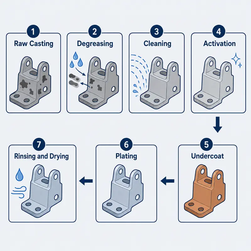
Zinc needs controlled pretreatment that removes oil, oxide, and polishing residue without attacking the substrate. ASTM B252 provides preparation guidance for specified ASTM B86 zinc alloys before copper, nickel, and chromium plating. The plater should qualify the cleaner, activation, rinses, undercoat or strike, and transfer time for the selected alloy and finish.
Aggressive cleaning can open surface defects or attack the zinc. Weak cleaning leaves an adhesion barrier. Freeze the approved sequence after first-article testing, and review any change to the cleaner, polishing compound, activation, or undercoat.
Rack or Barrel Plating
Use rack plating for larger, fragile, or appearance-critical hardware. Use barrel plating for small parts that can tolerate tumbling and contact marks.
| Decision factor | Rack plating | Barrel plating |
|---|---|---|
| Typical fit | Larger, delicate, or cosmetic parts | Small, durable parts with simple geometry |
| Part movement | Fixed orientation and defined contact | Continuous part-to-part contact |
| Main risks | Rack marks and higher handling cost | Impact, nesting, edge wear, and contact marks |
Small zinc die castings are often barrel plated with copper followed by nickel. Larger castings can suffer impact damage in a barrel. Qualify the process with the production-intent load, barrel fill, rack orientation, and cycle.
First Article and Lot Inspection
Approve a first article inspection only after the part completes the production-intent casting, polishing, cleaning, plating, drying, and post-treatment cycle.
- Inspect appearance under defined lighting, distance, and viewing angle.
- Measure thickness at named high-current and low-current locations.
- Check masked areas, dimensions, threads, and mating fits.
- Record the drawing revision, alloy, finish, process route, and test results.
ASTM B571 requires the buyer and supplier to specify the qualitative adhesion method and agree on acceptance criteria. ASTM B568 covers noncontact X-ray measurement of coating thickness. Use a cross-section to confirm the individual layers or failure interface.
The lot plan should define sampling, defect limits, traceability, and the response to a failed result. Keep each lot tied to the approved drawing, material, finish, and inspection records.
FAQs
How Should Buyers Choose a Zinc Alloy for Plated Hardware?
Choose the alloy from the strength, casting, dimensional, and finish requirements together. Zamak 3 is a common default and has strong finishing characteristics. Zamak 5 adds strength and hardness with plating behavior comparable to Zamak 3, while Zamak 7 supports thin walls and a good surface finish. ZA-12 supports plating, but its plating adhesion is lower than that of conventional zinc alloys. ZA-27 is not recommended for plating, so the drawing should name the approved ASTM B86 or UNS alloy rather than state only “zinc.”
When Is Electroless Nickel a Better Choice Than Decorative Electroplating?
Choose electroless nickel when uniform thickness or functional coverage on complex geometry matters more than a bright decorative finish. The coating builds more evenly because the process does not depend on electrical current distribution across the part. Zinc-specific pretreatment and an approved sample remain necessary because electroless nickel cannot correct a contaminated or porous substrate.
Can Secondary Machining Increase Plating Risk on Zinc Die Cast Parts?
Yes. Machining can expose subsurface pores, leave cutting-fluid residue, create burrs, or add sharp edges. Include every plated machined surface in the pretreatment and first-article plan. If machining occurs after plating, the drawing should identify the exposed zinc and the resulting break in coating protection.
Should Threaded Holes Be Tapped Before or After Plating?
Tap most threaded holes before plating, then mask them or size them for the approved coating buildup. Tap after plating only when final thread fit matters more than continuous coating protection. Post-plate tapping removes the deposit from the thread, so the drawing should state the sequence, masking requirement, thread class, and final gauge.
Can Heavy Copper Plating Repair Porosity in a Zinc Die Casting?
No. Heavy copper can level minor surface texture or bridge shallow cosmetic pits within a qualified process, but it cannot correct internal or connected porosity. If porosity affects adhesion, corrosion, a thread, or appearance, correct the casting process and reject parts outside the approved limit.
