

Zinc die casting suits thin-wall precision parts because molten zinc fills narrow sections and reproduces fine detail before the flow front freezes. The International Zinc Association reports that conventional zinc and ZA alloys have produced walls as thin as 0.15 mm, but that figure is a demonstrated extreme rather than a general design target.
The practical minimum depends on flow length, gate position, part size, die temperature, and feature geometry. Engineers should review wall transitions, tooling, porosity, tolerances, finishing, and inspection as one production system.
What Makes Zinc Suitable for Thin-Wall Die Casting?
High fluidity lets zinc fill narrow cavities, while the steel die repeats small features and datum relationships across production runs. This combination can reduce section thickness, post-machining, or part count when the design gives metal and displaced air controlled paths through the cavity.
Metal Flow Through Narrow Sections
Molten zinc can move through a narrow die section before the flow front freezes. This behavior supports thin housings, shields, brackets, and small structural frames that would be harder to fill with a less fluid alloy.
Flow length still sets a practical limit. International Zinc Association guidance places the rule-of-thumb minimum below 0.5 mm when the flow distance is under 50 mm, increasing toward 2 mm at about 200 mm. These figures are review points, not guaranteed limits. Gate area, runner balance, alloy, machine capacity, local geometry, and venting can shift the workable thickness.
Fine Features and Surface Detail
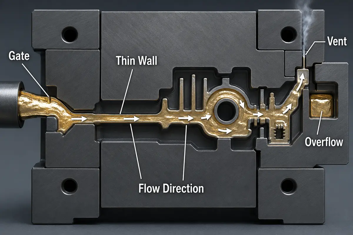
Zinc die casting can form fine ribs, lettering, pockets, cored holes, and textures in one shot. Deep or narrow details still need enough metal access and draft because an isolated feature may freeze early, trap air, or grip the die during ejection. Small radii and clear draw directions make these features easier to fill and maintain. The broader casting process guide explains how filling, cooling, part removal, and trimming affect the result.
Dimensional Repeatability in Production
A fixed steel die can repeat feature locations, but the tolerance must match how the tool forms the feature. Dimensions inside one die half are easier to control than dimensions that cross the parting line or depend on a moving slide.
Cooling conditions also affect size. International Zinc Association data show that post-casting dimensional change varies by alloy and cooling method. Tight-fit parts may need a defined measurement time, stabilization plan, and capability study. Critical bores, sealing faces, bearing seats, and datums may still need secondary CNC machining.
Which Design and Tooling Decisions Control Thin-Wall Quality?
Wall transitions, gates, vents, parting lines, draft, and ejection determine whether a thin-wall casting fills cleanly and leaves the die without distortion. Resolving these items before the toolmaker cuts steel reduces the risk of repeated sampling and die correction.
Uniform Wall Thickness and Gradual Transitions
Keep wall thickness as consistent as the load path permits. Abrupt changes cool at different rates, while isolated thick areas hold heat and can pull on nearby thin walls.
When added material is necessary, blend the transition instead of using a sharp step. A core can remove excess mass from a heavy pad or boss without removing the stiffness the part needs. The die caster should review each transition against gate distance, flow direction, and nearby functional surfaces.
Ribs, Bosses, and Fillets
Ribs, bosses, and fillets solve different design problems, so each feature needs its own mass and tooling review.
- Ribs stiffen a broad wall without thickening the whole section. Keep rib intersections light because excess mass can create sinks or shrinkage porosity.
- Bosses support fasteners, locating pins, or machined holes. Core a heavy boss and blend supporting ribs into its base to reduce uneven cooling.
- Fillets improve metal flow and remove sharp stress concentrations. International Zinc Association guidance suggests at least 0.4 mm in place of a sharp corner, while 1.6 mm is a common minimum for inside edges.
These values are starting points. Load, finish, wall thickness, and tool access may require larger radii or a different feature shape.
Gates, Vents, and Parting Lines
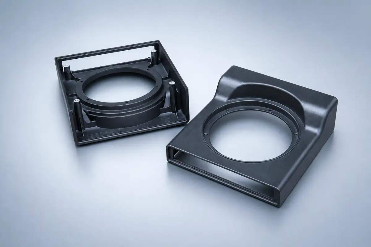
Gate position controls where metal enters and how far the leading edge must travel. A gate that sends metal around multiple corners before it reaches a thin section raises the risk of incomplete fill, cold shuts, and poor surface detail.
Vents and overflows receive displaced air and the leading metal front. Place them near the last areas to fill, but keep them away from sealing faces, threaded bosses, and cosmetic zones where trapped gas or trim marks would create a rejection risk.
The parting line affects filling, flash, trimming, and tolerance control. A flat parting line is easier to seal and maintain. A complex line may cross a visible or tolerance-sensitive surface, and dimensions across that line are harder to hold. Mark protected surfaces before the toolmaker fixes the gate, vent, overflow, and parting-line layout.
Draft and Ejection Strategy
Draft lets the casting release without scraping or bending. International Zinc Association guidance lists 1 degree on internal walls and 0.5 degree on external walls as common minimum starting points. Shallow ribs may need more draft.
Zero draft can work on selected features, but it requires careful die-side selection, positive ejection, and more tool maintenance. Ejector pins also need enough contact area and balanced placement. If too few pins carry the load, a hot thin wall can dent or bow.
What Defects Affect Thin-Wall Zinc Die Castings?
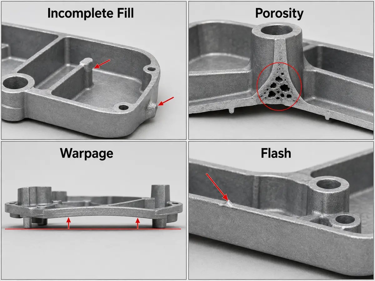
Common thin-wall defects include incomplete fill, porosity, warpage, flash, and ejection damage. Each defect points to a different combination of flow, gas control, local mass, die condition, or removal force.
Incomplete Filling and Surface Defects
Incomplete fill occurs when the metal front freezes before the cavity is full. Long flow paths, narrow gates, cold die areas, or abrupt section changes can leave a rounded missing edge or an unfilled rib.
When two fronts meet without bonding cleanly, the casting may show a cold shut. Turbulence, excess lubricant, or trapped air can also leave blisters, flow marks, and rough patches. Correct the fill pattern before raising pressure or temperature because a process change alone may move the defect to another area.
Gas and Shrinkage Porosity
Gas and shrinkage porosity can both create internal voids, but they need different corrective actions.
| Porosity type | Main cause | Review first |
|---|---|---|
| Gas porosity | Air or gas trapped during the fast fill | Shot profile, venting, vacuum support, lubricant use, and melt handling |
| Shrinkage porosity | Local volume loss as a thick or hot section solidifies | Wall transitions, isolated mass, thermal balance, and pressure transfer |
Pore location matters as much as total pore content. A void near a thread, seal, bearing seat, or load path can cause more damage than dispersed pores in a noncritical area. Secondary machining may expose pores below the casting skin, so the casting shrinkage guide connects hot-spot control with machining and inspection decisions.
Warpage From Uneven Cooling
Warpage develops when one area cools or contracts before another. Broad thin walls, uneven ribs, heavy bosses, and unbalanced cooling circuits can shift flatness or hole position.
Ejection can add more distortion while the casting is hot. The supplier may need to change cooling time, die temperature, ejector balance, or local geometry. Place datums on stable features and specify flatness only where the assembly needs it.
Flash, Trimming, and Ejection Damage
Flash forms when molten metal enters a gap at the parting line, slide shutoff, or worn die interface. The flash may fold over during tumbling or remain after trimming, leaving a sharp edge or assembly interference.
A poorly supported trim line can bend a light section, while an ejector pin can dent or crack a casting that sticks. The drawing should identify acceptable gate, trim, and ejector-mark zones so these process features stay off datums, sealing faces, and visible surfaces.
How Should Engineers Prepare a Thin-Wall Part for Production?
A production-ready release connects service loads and appearance requirements to alloy, tooling, machining, and inspection. Missing information at this stage can force a die change after the supplier casts samples.
Service Conditions, Loads, and Alloy Selection
Choose the alloy from the operating temperature, sustained load, impact, finishing route, and minimum wall requirement. Zinc alloys can creep under sustained stress as temperature rises, so a thin structural feature needs a time-and-temperature load case rather than room-temperature strength alone.
The International Zinc Association describes these common choices:
| Alloy | Useful design direction | Main review point |
|---|---|---|
| Zamak 3 | General die casting, ductility, and finish quality | Confirm strength and creep fit for the service load |
| Zamak 5 | Higher strength and hardness than Zamak 3 | Lower ductility can affect bending, riveting, or crimping |
| Zamak 7 | Higher fluidity and good surface finish | Confirm supplier availability for thin-wall production |
| High Fluidity alloy | Sections below 0.45 mm in suitable designs | Confirm alloy supply, tooling, and process capability before release |
Name the approved alloy on the drawing. The phrase “zinc alloy” is too broad when strength, aging, plating, or material documentation affects acceptance.
Critical Dimensions and Tolerance Priorities
Mark critical-to-function dimensions and relax features that do not affect assembly. Tolerances across a parting line, moving slide, or broad flexible wall cost more to hold than dimensions formed in one die half.
Build the datum scheme around casting, trimming, machining, and measurement. Classify each feature as as-cast controlled, secondary machined, or reference-only. This prevents the supplier from chasing an as-cast tolerance that machining should control. Rollyu Precision can review DFM, dimensional inspection, material documentation, and traceability, but the drawing or quality plan must state the acceptance limits.
Finish and Cosmetic Requirements
Define the visible zone, permitted defects, texture, color, gloss, and protected contact surfaces. “Cosmetic finish” does not give the supplier a measurable acceptance rule.
Zinc supports conversion coatings, paint, and plated finishes, but the casting surface must suit the selected process. Plating thickness can vary inside threaded, ribbed, or fluted holes, while trapped solution can affect steel fasteners. State whether the supplier should mask, chase, or cut threads after plating. Keep gate scars, ejector marks, and parting-line witnesses on noncosmetic surfaces where the design allows.
Secondary Machining and Inspection
Use secondary CNC machining for sealing faces, bearing seats, reamed holes, precision threads, and datums that exceed economical as-cast control. Keep machining allowance local because a deep cut can expose subsurface porosity.
Match each inspection method to the failure risk:
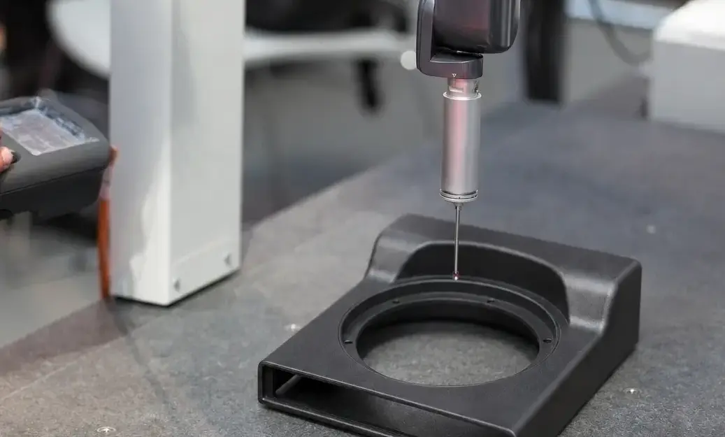
- CMM inspection checks position, flatness, and machined geometry.
- Thread and bore gauges verify assembly features.
- Leak testing checks pressure-retaining parts against the stated acceptance limit.
- X-ray, computed tomography, or sectioning can assess internal porosity when void location affects function.
The control plan should state when inspection occurs and whether samples include trimming, finishing, and machining. Measurements taken before those operations may not represent the released part.
Drawing Approval and Tooling Release
Approve tooling only after the supplier closes the DFM review and records the manufacturing route. The release package should include:
- A controlled 3D model and 2D drawing with matching revision status.
- The named zinc alloy, service conditions, and expected annual volume.
- Critical dimensions, datums, finish zones, and acceptable process marks.
- The approved parting line, gate, vent, overflow, slide, draft, and ejector layout.
- The sampling, capability, inspection, and documentation plan.
For zinc die casting parts that need CNC machining or finishing, approve the casting and post-casting operations together. Do not authorize tool cutting while responsibility for a critical feature or acceptance check remains open.
Frequently Asked Questions
Is Zinc or Aluminum Die Casting Better for a Thin-Wall Precision Part?
Zinc often fits smaller parts that need thin sections, fine detail, and a smooth surface. Aluminum has much lower density and may fit better when weight or higher-temperature service controls the decision. Compare the complete load case, wall geometry, corrosion plan, annual volume, and finishing route.
When Is CNC Machining a Better Choice Than Zinc Die Casting?
CNC machining usually fits low volumes, frequent design changes, thick solid geometry, or tight datum relationships that would require extensive post-machining on a casting. Die casting adds tool cost and a tooling-release step, while CNC machining starts without a dedicated die. The casting vs machining guide explains how volume, geometry, tolerance, and lead time change the choice.
Does Reducing Wall Thickness Always Lower the Total Part Cost?
No. A thinner wall saves material only when the die fills consistently and the part survives ejection, trimming, finishing, and assembly. Pushing the wall below stable process capability can increase tool complexity, sampling time, scrap, inspection, and correction. Evaluate total cost at the approved geometry and production rate.
Can Threads and Fastening Features Be Cast Into a Thin-Wall Zinc Part?
Some external threads, coarse internal forms, cored holes, bosses, studs, and locating features can be cast in. Most internal machine threads are cheaper to tap after casting because a cast internal thread may require an unscrewing core that slows the cycle. The design still needs enough boss wall, thread engagement, chip clearance, and material around the fastener load.
Can a Thin-Wall Zinc Die Casting Replace a Multi-Piece Assembly?
Yes, a zinc die casting can combine walls, ribs, bosses, mounts, shields, and locating features in one part. Consolidation works when the geometry can fill, release from the die, and carry the load without inaccessible undercuts or heavy isolated sections. Compare the new tooling and inspection plan with the labor, tolerance stack, fasteners, and failure points in the existing assembly.
