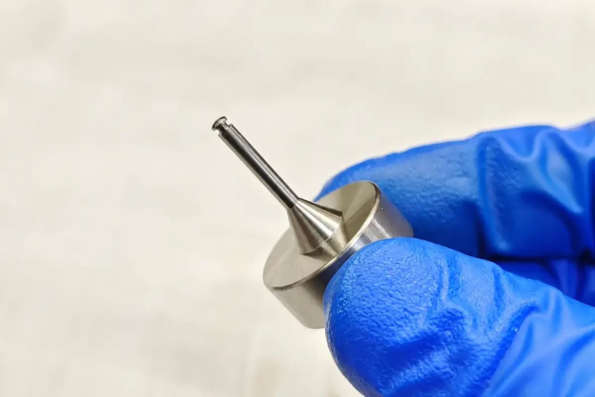
CNC micro machining cuts fine holes, slots, and profiles in metal and engineering plastic parts. How the finished feature is verified matters as much as how it is cut. Hole diameter, position, surface condition, and internal burrs each need their own drawing requirement and inspection method.
What Is CNC Micro Machining?
CNC micro machining uses very small cutting tools and closely controlled machine motion to produce fine features. Micro milling forms pockets, slots, and profiles, micro drilling makes holes, and turning produces small diameters and other rotational features. BIG DAISHOWA classifies cutters under 3 mm in diameter as micro tools, with geometry designed for that size rather than scaled down from standard tools. The part itself does not have to be small: a large housing or mounting plate can carry a few local features that need micro tooling.
Feature size and tolerance are separate. A small nominal diameter does not imply a tight tolerance, and the drawing still has to state the permitted variation.
What Makes Small Features Difficult to Machine?
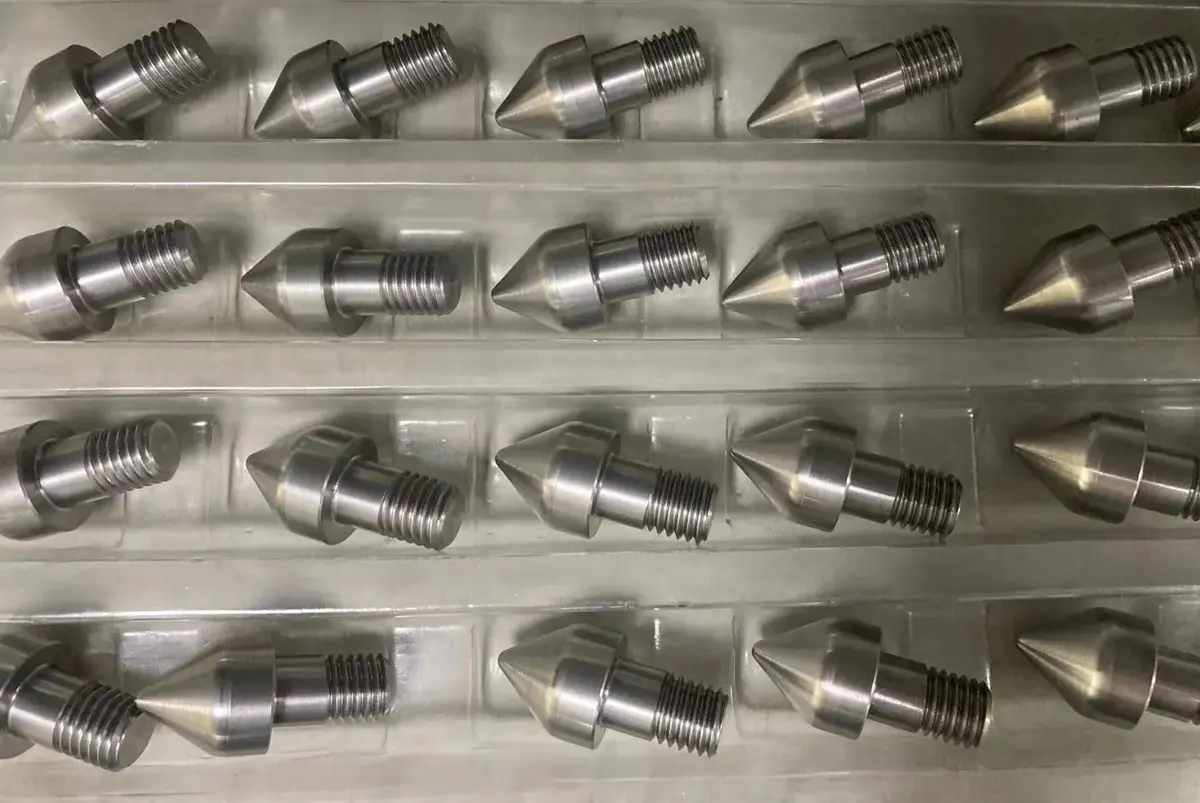
Small features get harder to machine as tool reach grows, chip space shrinks, and the surrounding material gives less support, which is why depth and nearby geometry matter as much as width.
Micro Holes and Intersections
Deep holes give chips a longer path out of the cut, and a micro drill’s flutes leave little room to carry them. Plan tool geometry, chip evacuation, and any coolant or lubrication around the material and hole depth.
Cross holes add a hidden edge where one hole breaks into a bore or channel, and burrs tend to form there. Settle during DFM how that intersection will be deburred and how inspectors will reach it. The collimator tube case later in this article shows how easily a routine gauging step can hide those burrs.
Narrow Slots and Thin Walls
A narrow slot limits cutter diameter, and a deep slot needs a longer reach. Long, slender tools deflect more easily, and thin walls can vibrate or move under cutting forces, which affects both size and surface finish. Where function allows, widening a slot, reducing pocket depth, or adding support gives the machinist a more stable setup. An internal corner radius cannot be smaller than the cutter radius, so size it to an available cutter before the design is fixed.
Tool Runout and Chip Formation
Tool runout, where the cutter does not rotate exactly about its centerline, loads the cutting edges unevenly. One edge ends up carrying most of the cut and wears out first. BIG DAISHOWA reports a steel drilling application with a 0.118 in. (3 mm) carbide drill in which a holder with 0.00008 in. runout produced 2,300 holes, while one with 0.00060 in. runout produced only 800. Runout control starts with the spindle, holder, and cutter as one assembly.
Chip load, the feed per cutting edge, matters just as much. According to BIG DAISHOWA, micro end mills cut best when the chip load is close to the cutting-edge radius. Below that, the tool rubs instead of cutting and generates more heat, while a chip load well above the radius can break the tool early. Raising spindle speed or switching to a smaller tool often does not improve results on its own. Cutting conditions have to fit the cutter geometry, material, and chip evacuation together.

How Does Material Choice Affect Micro Machining?
Choose the material for its operating requirements first, then build the machining process around it, and confirm any substitution with the design engineer. The grade still changes how the part cuts and how stable its dimensions stay.
| Material | Machining Consideration | DFM Priority |
|---|---|---|
| Aluminum alloys | Burrs, chip evacuation, and tool adhesion can affect drilled features. | Match tool geometry and chip control to the alloy and hole depth. |
| Free-cutting brass such as C36000 | C36000 is the benchmark free-cutting brass, rated 100 on the copper-alloy machinability scale. | Confirm the specified alloy, including any limit on lead content, meets the part’s operating requirements. |
| Austenitic stainless steel | Chip formation and evacuation can be difficult in drilling. | Plan chip removal and access to internal edges. |
| Titanium alloys | Drilling can work-harden the hole surface and affect later operations, and chips can be hard to clear. | Coordinate the drilling sequence, cutting-edge geometry, and chip evacuation. |
| Engineering plastics | Machining heat, internal stress, and moisture uptake affect dimensional stability differently by grade. | Control heat and account for the polymer’s condition when machining and measuring. |
Ensinger recommends good heat dissipation and adequate fixturing during plastic machining, since heat and released internal stress can push parts out of tolerance. Set tolerances and measurement conditions for the actual grade and geometry.
How Are Micro-Machined Features Inspected?
Match each inspection method to the requirement it verifies. Dimensional measurement establishes size and geometric relationships, while visual or optical checks find visible burrs and surface defects.
Dimensions and Datum Relationships
Coordinate measuring machine (CMM) inspection checks accessible dimensions and datum relationships when the probe and measurement uncertainty suit the tolerance. Probe access, fixturing, and alignment determine the setup. For a locating hole, measure the diameter and its position relative to the specified datums. Optical measurement checks visible edges and profiles without contact, dedicated gauges check selected sizes or fits, and surface roughness needs its own texture measurement.
Burrs and Hidden Intersections
Hidden burrs need an inspection sequence designed around them. In Rollyu Precision’s 416 stainless steel collimator tube case, tempered AISI 416 tubes had Ø0.50 mm side holes intersecting an internal bore. A plug gauge inserted into the large bore pushed burrs back into the cross holes, so the bore looked clean while the defect remained. The revised sequence checks the small holes first with a micro pin, then examines the parts under a microscope from two angles before the bore is gauged.
How Does Rollyu Precision Support Micro Machining Projects?
Micro features need the DFM review, machining route, and inspection method to follow the same plan. Rollyu Precision handles all three for prototype and production orders.
DFM and Process Selection
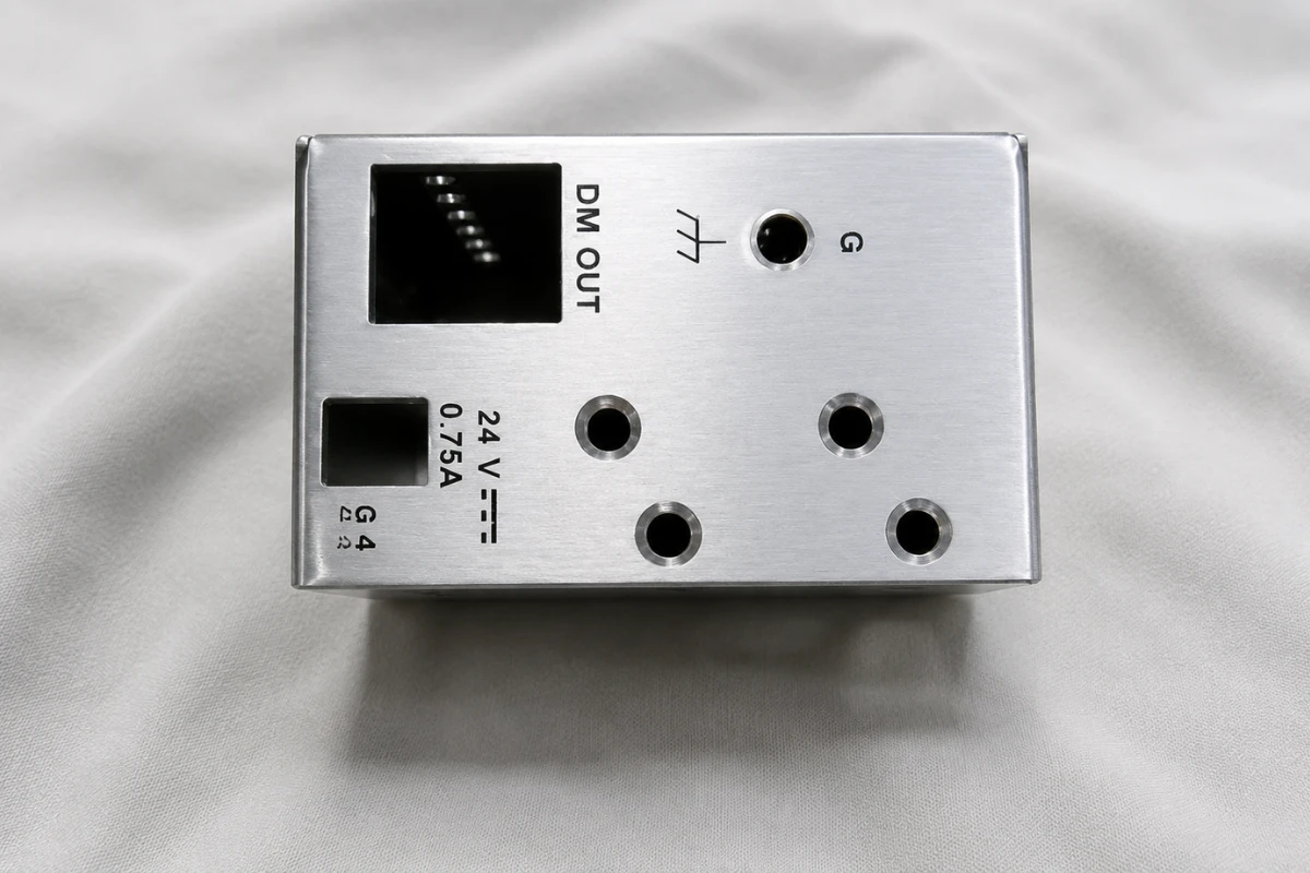
Rollyu’s CNC machining capabilities include 3-, 4-, and 5-axis machining, milling, turning, and micro machining. During DFM, the team reviews tool access, workholding, and critical tolerances together. For features on different faces, that means planning how the setup locates the part, how the cutter reaches each feature, and how inspectors verify the result. Discuss any proposed change against the drawing’s functional requirements.
Inspection Records and Traceability
The inspection package is set at quotation, so list the critical characteristics and the records you need before the order is placed. Rollyu verifies dimensions with CMM and optical inspection and can supply dimensional reports, first article inspection (FAI) documentation, Material Test Reports, Certificates of Conformance, and material traceability. The company states that its quality management system is certified to ISO 9001:2015 and ISO 13485:2016.
Preparing a Part for Quotation
Mark the critical small features on the 2D drawing and send it with the 3D model. The quote also depends on:
- Material grade and condition
- Quantity, and whether the order is a prototype or production run
- Critical tolerances, datums, surface finish, and edge requirements
- Inspection reports and material documentation the order needs
Ask for a DFM review of the machining route, feature access, and inspection scope before you place the order.
Frequently Asked Questions
What Drives the Cost of a Micro-Machined Part?
Setup, tooling, machining time, material, and inspection scope drive the quote. Deep or unsupported features add machining difficulty and time, and a low quantity spreads setup cost over fewer parts. Tight tolerances add both machining and inspection effort, which makes them worth reserving for features whose function depends on them.
Can Small Aluminum Features Be Anodized?
Yes, but anodizing changes dimensions, including hole and thread sizes. The oxide layer grows thicker than the aluminum it consumes, and the amount of change depends on the alloy and process conditions. Agree on coating thickness, masking, and final dimensions with the anodizer before setting machining allowances.
Does One Successful Prototype Prove Production Repeatability?
No. A passing prototype confirms the checked requirements on that sample only. Production repeatability needs measurements from repeated parts under stable process conditions, and the NIST/SEMATECH process-capability approach compares that stable-process variation with the specification limits.
Sources
- BIG DAISHOWA, Micromachining: What to Know about Holders, Tooling and Machines: Micro tool size, local micro features on larger parts, runout, and chip load.
- Sandvik Coromant, Drilling Tips and Techniques for Different Materials: Burrs, adhesion, chip evacuation, and work hardening by workpiece material.
- Copper Development Association, Brass: The Cost-Effective Choice: C36000 machinability rating.
- Ensinger, Machining Recommendations for Semi-Finished Engineering Plastics: Heat, internal stress, moisture, and dimensional stability. Manufacturer guide hosted by Curbell Plastics.
- Aluminum Anodizers Council, Anodized Aluminum FAQ: Dimensional change from anodizing and its dependence on alloy and process conditions.
- NIST/SEMATECH e-Handbook, What Is Process Capability?: Comparing stable-process variation with specification limits.