Sheet metal prototyping turns a CAD model into test parts cut and formed from sheet stock, with welding, hardware, and finishing added where the design calls for them. Use the prototype to check finished interfaces, assembly access, and any operating behavior the part must demonstrate before you release the next design revision.
Define What the Sheet Metal Prototype Needs to Prove
Decide what the prototype must prove before you order it, because that goal sets the material, construction, and inspection the sample needs. For an electronics enclosure, list the circuit-board space, connector clearance, and lid access the test will check. For a bracket, name the mounting interface and the load case.
A form-and-fit prototype needs accurate interfaces, clearances, fastener access, and installation order. A functional prototype also has to behave like the production part. If the alloy, thickness, or joint arrangement could change the test result, use the intended ones. When the sample uses a substitute material or joint, record it with the acceptance criteria so a later revision does not lean on results the prototype was never built to show.
Prepare CAD Files for the Formed Part
Send the fabricator a file set it can build from without guessing: the formed 3D model, drawing, bill of materials, and any cutting files you supply.
Match Material, Thickness, and Revision
Call out the material grade, temper or condition, and sheet thickness for every part. “Aluminum” alone defines neither the stock nor how it forms. On the drawing, dimension and tolerance the features that control assembly, such as mounting-hole locations, flange heights, and mating surfaces. Add finish and inspection notes where they apply. The 3D model defines the shape, while the drawing carries the requirements the fabricator must hold. When a feature changes, update every affected file before you release the revision.
Confirm the Flat Pattern With the Fabricator
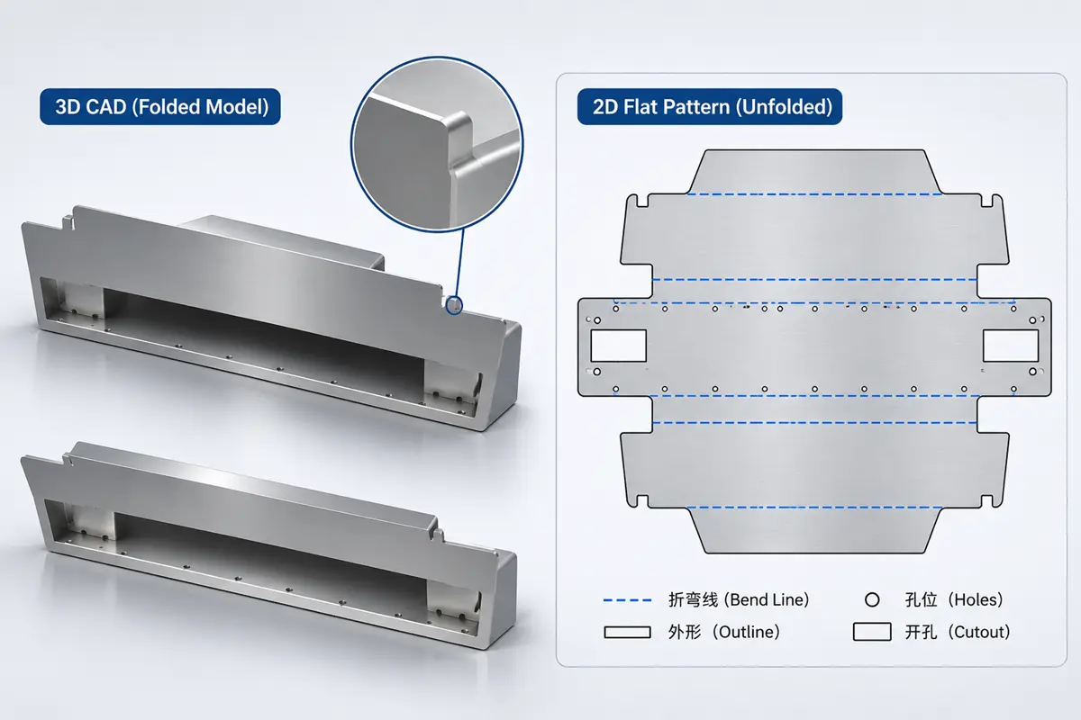
The flat pattern is the blank cut before forming, and its developed length includes a bend allowance for every bend. Bend allowance is the arc length of the bend measured along the neutral axis, the layer that keeps its original length while the material bends. The K-factor locates that neutral axis as its distance from the inside bend surface divided by sheet thickness.
The CAD development settings need to match the fabricator’s material, bend radius, and tooling, because a mismatched K-factor changes the blank size. Agree who prepares the final cutting file, and keep finished-part dimensions on the formed drawing rather than the flat pattern.
Plan the Cutting, Bending, and Joining Sequence
Access drives the build sequence. Cutting produces the blank, and every bend changes the room left for later forming, welding, and hardware installation.
Review Bending Access and Feature Placement
Check the proposed bend sequence against the punch, die, and surrounding geometry. Tall walls and return flanges can block a later bend. Holes or slots close to the bend zone can distort as the material forms. Review their positions on the formed part as well as in the flat pattern.
Springback is the elastic recovery that opens the bend angle after the press brake releases the part, and operators overbend to compensate. Because the amount varies with material properties, thickness, bend radius, and tooling, the fabricator sets springback compensation for its own setup.
Plan Welding and Hardware Installation
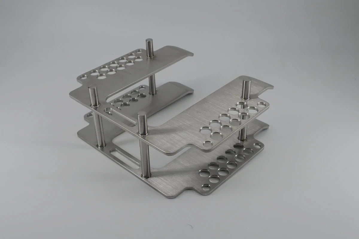
Settle weld access and hardware installation before cutting. Inserts or fasteners installed too early can block forming tools, and bends completed too early can close off access for installation. Put the joint details, hardware part numbers, and assembly bill of materials into the manufacturing review. For an enclosure, also confirm how the panels locate and how tools reach each joint.
Welding heats the joint locally, and the weld and nearby metal contract as they cool. That contraction can pull a thin panel out of flat or shift a mounting feature. Fit-up, restraint, joint design, and welding procedure all influence how far the part moves. Schedule dimensional checks after any operation that could change an assembly interface.
Check Fit and Function on the Finished Prototype
Inspect the features that decide whether the sample can complete its test. Dimensional results, assembly trials, and functional tests answer different questions.
| Prototype Check | What to Check | Decision It Supports |
|---|---|---|
| Material and thickness | Specified grade, material condition, sheet thickness, and requested material records | Confirm the sample’s material baseline |
| Formed geometry | Bend angles, flange heights, hole locations, and specified flatness | Confirm finished interfaces against the drawing |
| Hardware and assembly fit | Fastener seating, mating clearances, tool access, and installation sequence | Find interference or needed assembly changes |
| Functional behavior | Load, motion, thermal, or other operating conditions in the test plan | Decide whether the design meets the test objective |
Split the inspection work before the build: name who measures the critical features and who runs the functional tests in the engineering test plan. If Rollyu Precision handles the dimensional side, its in-process and final inspection includes coordinate measuring machine (CMM) inspection and dimensional reports. Mark the critical features and report scope during the manufacturing review.
Fit checks need the mating parts or a defined fixture. Record any interference, inaccessible hardware, or hand adjustment the assembly needed. Keep the as-built configuration and test conditions with the results, since the next revision will be measured against them.
Feed Test Results Back Into the Design
Trace a fit problem in the sheet metal assembly to its cause before you move a feature in CAD. A misplaced hole might come from the drawing, flat-pattern development, bend-angle variation, or weld distortion. Each cause has its own fix: correct the drawing, adjust the K-factor or bend table, review springback compensation, or change the weld sequence and fixturing.
Log the affected feature, the measured result, and the agreed change for every finding. Update the affected files, then recheck the changed interfaces on the next sample. If the first piece needed trimming, rebending, or other hand work, document that work and resolve its cause in the revised design or manufacturing plan.
For a repeat order, send the released revision together with the findings that changed it. The fabricator then has what it needs to requote the revised geometry, operations, inspection scope, and quantity.
Build Sheet Metal Prototypes With Rollyu Precision
Rollyu Precision builds custom sheet metal prototypes and low-volume parts, and each job starts with a design for manufacturability (DFM) review.
Fabrication and Finishing in One Workflow
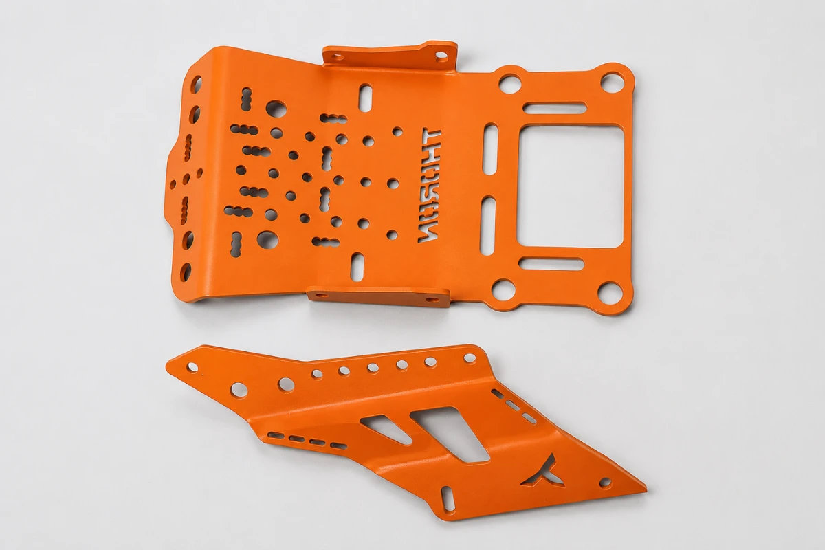
Rollyu Precision’s sheet metal fabrication service covers laser cutting, press-brake bending, TIG, MIG, and spot welding, plus deburring, for brackets, housings, and enclosures in stainless steel and aluminum. Finishing options include anodizing for aluminum, powder coating, and brushing or polishing. Use the DFM review to settle bend access, weld locations, hardware, and finished clearances together, including any coating buildup at mating features.
Inspection and Documentation for Critical Features
Alongside dimensional reports, Rollyu can provide first article inspection (FAI) records, Certificates of Conformance, Material Test Reports, and lot-level material traceability when the order calls for them. Tie each requested record to the drawing revision and the test-critical features. A dimensional report supports review of mating features, while material records document the supplied stock.
Send a Quote-Ready File Package
Send Rollyu a package that lets the team quote the build and its follow-up work:
- Current 3D model and drawing at the same revision
- Sample quantity and target delivery date
- Assembly details, hardware, and finish requirements
- Test-critical features and the inspection records you need
- Expected follow-up quantity, if the prototype leads into a planned low-volume run
With that package, the team can review fabrication and finishing together, flag design changes, and confirm the inspection and documentation scope before the build starts.
Frequently Asked Questions
Does Sheet Metal Prototyping Need a Dedicated Stamping Die?
Not if laser cutting and press-brake bending can produce the geometry. Neither process needs a part-specific production stamping die. Unusual forms or restricted tool access may still call for custom tooling or fixtures. Ask for those items to be priced separately from the part.
Should the First Prototype Have the Final Surface Finish?
Apply the final finish when it affects the test result. Coating buildup can change mating clearances, and a corrosion or wear test needs the specified surface treatment. A first build that only checks geometry can stay unfinished.
Can One Prototype Assembly Use Different Sheet Thicknesses?
Yes. Make each thickness a separate part with its own material and drawing definition. Review the joints and hardware for the actual thickness combination, then check the completed assembly against its fit and functional requirements.
Sources
- SOLIDWORKS Help, Bend Allowance and Bend Deduction: Bend allowance as the arc length of the bend along the neutral axis.
- Autodesk Fusion Help, Sheet Metal Rule Reference: Material thickness, bend radius, and the K-factor definition.
- Autodesk Fusion Help, Sheet Metal Components: Sheet metal rules that set thickness and bend radius for each component.
- SSAB, 20 Questions About Bending: Neutral axis, springback, overbending, and factors that affect the final bend angle.
- TWI, Distortion: Types and Causes: Weld contraction and the factors that affect welding distortion.