

Plan soft machining from the delivered condition backward: remove bulk material before hardening, then reserve any dimension that heat-treatment movement can compromise for post-treatment machining or grinding. The split follows the alloy, starting condition, thermal cycle, geometry, datum scheme, final hardness, and inspection requirement.
Manufacturing Engineers, Process Engineers, and Supplier Quality Engineers balance feature assignment, route-specific stock, datum preservation, and state-change inspection to control distortion without paying hardened-material cutting costs across every feature.
Soft Machining Starts With the Final Part Condition
Soft machining covers conventional milling, turning, drilling, boring, or threading while the alloy remains in a machinable state, typically annealed or normalized before final hardening. This phase includes bulk roughing, semi-finishing, and completing any noncritical features whose location and fit will remain acceptable after the thermal cycle.
Drawing tolerances dictate the boundary between soft machining and finish operations. Critical surfaces that control bearing fits, dynamic seals, precision alignment, or structural mating faces often shift during quenching or tempering, requiring final sizing after heat treatment. Conversely, noncritical clearance pockets, weight-reduction reliefs, and external chamfers can finish in the soft state, eliminating expensive secondary setups.
Choose the Material State Before Assigning Features
Cutting decisions depend on the alloy’s metallurgical state at each routing step. Final hardness alone is insufficient to plan machining because an annealed forging, pre-hardened plate, through-hardened pin, and a case-hardened gear behave differently in the machine.
Incoming Material Condition and Final Hardness
Process routing must account for the supplied condition alongside every planned thermal step, whether stress relief, vacuum hardening and tempering, carburizing, nitriding, solution treating, or precipitation aging. Pre-hardened alloys (such as 4140 pre-hardened to 28–32 HRC) frequently allow shops to machine parts directly to final dimensions, avoiding thermal distortion entirely at the expense of moderate cutting speeds.
In contrast, annealed tool steels (such as D2, A2, or H13) permit high-efficiency bulk removal during roughing, but dimensional movement during hardening requires dedicated finish grinding allowances. Case-hardened parts introduce a distinct boundary: post-hardening finishing must clean up distortion without grinding through the effective case depth into the softer core.
Heat-Treatment Route and Distortion Risk
Thermal cycling alters part geometry through the relief of residual machining stress, thermal gradients during rapid quenching, and volumetric changes during martensitic phase transformation. Long shafts, thin-walled housings, deep asymmetric pockets, and unbalanced cross-sections amplify this movement. For distortion-sensitive geometries, adding a stress-relief anneal between rough machining and semi-finishing stabilizes the workpiece before final hardening, allowing the machinist to correct roughing-induced movement before the final thermal cycle.
Assign Each Feature to the Right Manufacturing Stage
Feature assignment balances part function, distortion sensitivity, tool clearance, and machine capability. A technical drawing for CNC machining defines the finished part, but the manufacturing routing determines when each individual surface achieves that condition.
| Feature type | Soft-machining action | Post-treatment action | Main decision trigger | Final verification |
|---|---|---|---|---|
| Bulk pockets and external contours | Remove most stock and create stable access | Finish only where the final tolerance or surface requires it | Material-removal cost, wall stability, and distortion risk | Size, wall condition, and profile as specified |
| Datum faces and locating diameters | Establish provisional references with finishing stock where needed | Recut or grind the datum before related critical features | Final position, runout, flatness, or alignment depends on the datum | Datum-based dimensional report |
| Precision bores | Drill or rough-bore undersize | Bore, hone, grind, or hard-finish to final size when movement threatens fit | Bore tolerance, roundness, position, and final hardness | Bore size, form, and position |
| Bearing, seal, and sliding diameters | Turn oversize with controlled stock | Grind or hard-turn after heat treatment | Fit, runout, straightness, roundness, or surface requirement | Diameter, form, runout, and roughness |
| Threads | Create before hardening when the thermal route will preserve fit and position | Finish by a suitable hardened-material process when final condition requires it | Thread class, location, distortion, surface treatment, and tool access | Functional gauge and specified positional check |
| Noncritical holes and relief features | Complete in the soft state when later movement remains acceptable | Inspect and correct only if the route requires it | Clearance, assembly margin, and treatment effects | Drawing-defined size and position |
| Case-hardened functional surfaces | Leave stock tied to the case-depth plan | Remove only the amount allowed by the final case requirement | Effective case depth after all finishing | Final size, surface, hardness, and case evidence when specified |
Bulk Geometry and Section Balance
Roughing should clear high-volume stock before hardening, opening tool clearance for grinding wheels, hard-turning inserts, or EDM electrodes. However, roughing must not compromise structural rigidity. Leaving walls too thin or removing material asymmetrically creates localized stress imbalances that warp in the furnace, turning low-cost roughing into uncorrectable heat-treatment scrap.
Datum Scheme Progression
Pre-hardening datums serve primarily to locate roughing and semi-finishing operations. When final drawing callouts tie tight tolerances to primary datums, the post-treatment sequence must true those datums before finishing associated journals, bores, or patterns. On shafts, this means center holes and locating journals must be skim-ground or lapped after heat treatment to eliminate thermal runout before grinding outer bearing seats.
Holes, Threads, and Secondary Geometry
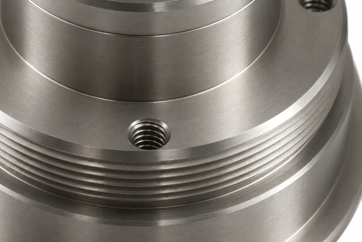
Standard clearance holes, counterbores, noncritical tapped holes, and deburring chamfers should finish in the soft state. For threaded features, cutting after hardening requires specialized solid carbide thread mills or EDM, increasing cycle time. Unless a thread requires extreme pitch-diameter precision or risks heavy scale accumulation during uncontrolled atmospheric heat treatment, machine threads prior to hardening and protect them with stop-off paint or graphite plugs where carburizing or decarburization threatens the profile.
Set Machining Allowance for the Actual Route
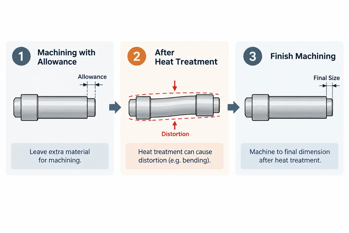
Machining allowances must be calculated surface by surface rather than applied as a uniform blanket offset across the model. Allowances must absorb worst-case thermal warp and surface decarburization while remaining thin enough to grind or hard-turn efficiently.
Stock Calculation for Thermal Movement
Stock values derive from alloy hardenability, part aspect ratio, section asymmetry, quench severity (oil, water, high-pressure gas, or salt bath), and fixturing method.
- Undersized stock: Leaves low uncleaned spots on warped surfaces, resulting in scrapped parts.
- Excessive stock: Forces prolonged grinding passes, generates thermal grinding burn, accelerates wheel loading, and risks drawing the surface temper.
Validated production allowances rely on empirical data from pilot runs, measuring dimensional shift across the quench to establish tight minimum-maximum stock boundaries.
Case Depth and Surface Condition Constraints
Carburized, carbonitrided, and nitrided components require coordinating the case-depth specification with the finishing allowance. A surface calling for an effective case depth of 0.8 mm to 1.2 mm cannot support a 0.5 mm finish grind without risking partial removal of the hard wear layer. Similarly, vacuum or protective atmosphere heat treatment prevents surface scaling and decarburization, allowing thinner grinding stock than open-atmosphere furnace runs that demand heavier cleanup cuts.
Finish Critical Features After Heat Treatment
Hard finishing rectifies thermal distortion and imparts final functional surface textures, such as low Ra values for dynamic oil seals or bearing raceways.
Grinding, Hard Turning, and EDM Selection
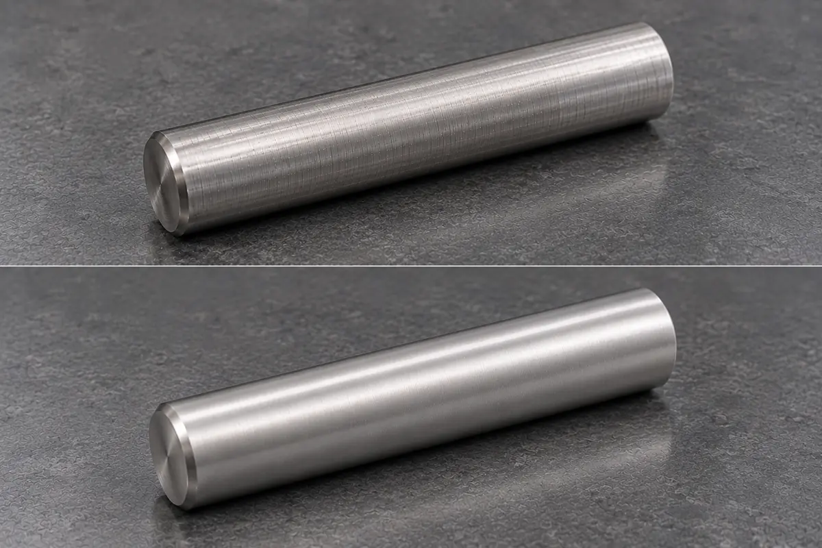
Cylindrical, surface, and centerless grinding reliably hold sub-micron tolerances and fine finishes on steels hardened above 58 HRC. Hard turning and hard milling using PCBN or ceramic tooling provide cost-effective alternatives for complex contours, tapers, and interrupted cuts on rigid CNC lathes and 5-axis mills up to roughly 62 HRC. Wire EDM and sinker EDM address tight internal splines, keyways, sharp corners, and deep blind features where mechanical cutting tools deflect or cannot reach.
Machine Datum Setup and Alignment
Before cutting finished features, the setup must true the locating surfaces directly on the machine tool. Skim-cutting the primary mounting face or truing center holes establishes a reliable reference frame aligned with the part’s post-quench geometry. This practice prevents thermal warp from being machined into finished bores and journals, ensuring true position and concentricity conform to the drawing.
Inspect at Every State Change
State-change inspection isolates dimensional movement to the specific process that caused it, preventing disputes between machining cells and thermal processing vendors.
Pre-Heat-Treatment Baseline
Before transferring parts to heat treatment, quality control documents the incoming state:
- Material heat lot and certification verification
- Current revision of CAD and routing traveler
- Critical reference dimensions and provisional datum runouts
- Remaining finish stock on all surfaces marked for hard machining
This baseline confirms sufficient cleanup stock exists before the part enters the furnace.
Heat-Treatment Receiving Inspection
Upon return from heat treatment, inspect the lot before releasing it to the machine shop floor. Verify surface hardness (HRC, HRN, or Vickers microhardness) against the print. Measure overall straightness, flatness, and critical stock envelopes to confirm the material cleaned up without exceeding allowable distortion limits. Check parts for quench cracking, excessive oxidation, or surface contamination that could damage grinding wheels or tooling.
Final Acceptance and Verification
Final inspection verifies the part against the drawing datum structure after all machining, grinding, and surface treatments conclude. CMM inspection evaluates 3D profile tolerances, true position, perpendicularity, and datum relationships. Hardness testers, air gauges, bore micrometers, and stylus profilometers verify local material properties, bore geometry, and surface roughness requirements that coordinate data alone cannot confirm.

Use Rollyu Precision for a Controlled Multi-Stage Route
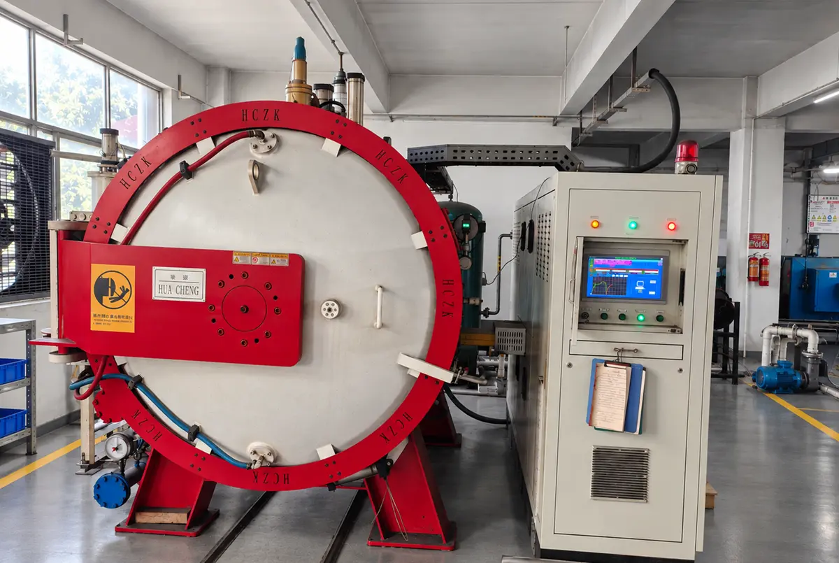
Engaging Rollyu Precision during early routing development aligns soft-machining allowances with proven thermal processing and finishing capabilities. Rollyu provides multi-axis CNC milling, CNC turning, Wire EDM, DFM engineering reviews, surface and cylindrical grinding, controlled tool-steel heat treatment, CMM dimensional reporting, and comprehensive material traceability.
DFM and Feature-Level Process Planning
Submitting CAD models and 2D drawings with complete material callouts, required thermal cycles, core and case hardness specifications, and inspection requirements allows Rollyu’s engineering team to deliver a feature-level process plan. This review identifies potential distortion triggers such as thin cross-sections or unbalanced stock removal, assigns correct pre-treatment stock allowances, and determines whether intermediate stress-relief cycles are required before finish machining.
Machining, Finishing, and Traceability Evidence
Rollyu Precision’s CNC machining capabilities span multi-axis milling, precision turning, and EDM, supporting integrated production from raw stock through final hard finishing. Rollyu defines process ownership and quality documentation across every phase:
- Controlled traveler tracking part status through machining, heat treatment, and grinding
- First-article and state-change inspection logs tracking distortion trends
- Certified heat-treatment charts and hardness test reports
- Final CMM inspection reports referenced to drawing datums
- Material Test Reports (MTRs) validating chemical composition and mechanical properties
Frequently Asked Questions
What machining operations should never be completed in the soft state?
Features with tolerances tighter than typical thermal distortion ranges should not finish in the soft state. These include bearing journal fits, precision dowel hole locations, seal counterbores requiring low runout, and high-flatness sealing faces. Quenching movement will warp these geometries beyond standard drawing limits, requiring post-hardening grinding, hard turning, or honing.
How do engineers compensate for internal thread shrinkage during heat treatment?
When internal threads must be cut before hardening, machinists use specialized oversize taps (such as GH-limit taps with higher pitch-diameter allowances) to compensate for thermal shrinkage, scaling, or subsequent surface coatings. For tight Class 3B threads in high-distortion tool steels, hole locations can be rough-drilled in the soft state and threaded via carbide thread milling or EDM after hardening.
When does pre-hardened alloy steel replace the soft-machining and hardening route?
Pre-hardened alloys (like 4140 or P20 at 28–32 HRC) replace multi-stage hardening routes when the application requires moderate structural strength, toughness, and fatigue resistance rather than high wear resistance. Choosing pre-hardened stock eliminates furnace lead times, thermal warp, and secondary grinding operations, provided the design can tolerate lower hardness and increased tool wear during milling and turning.
How is minimum grinding stock calculated on long slender shafts?
Minimum grinding stock for shafts equals the total radial thermal runout (total indicator reading) across the length, plus surface cleanup allowance (typically 0.1 mm to 0.2 mm on diameter for decarburization or scale), plus machine setup repeatability margin. If an oil-quenched shaft exhibits 0.3 mm TIR runout after heat treatment, the soft-turned diameter must carry at least 0.5 mm total diametral stock to guarantee complete cleanup without leaving unground low spots.
