
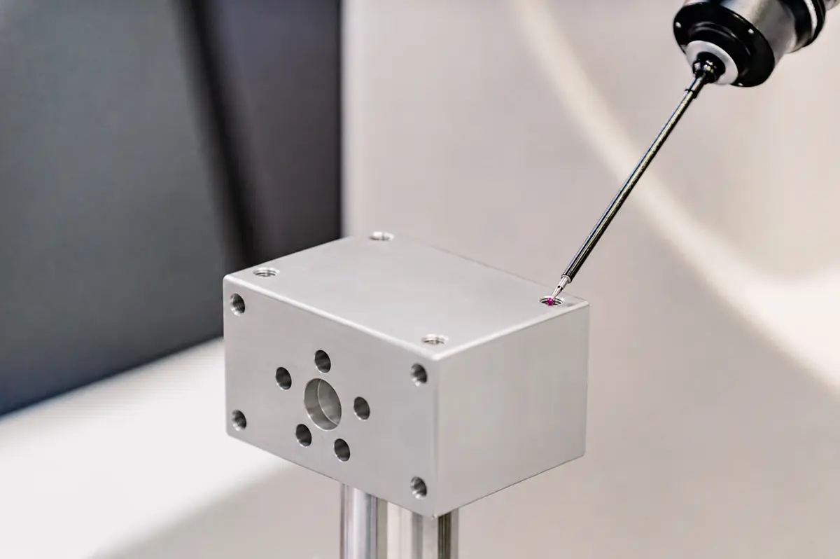

A technical drawing for CNC machining should state the requirements that a 3D model does not make unambiguous, including controlled dimensions, datums, threads, materials, finishes, and revision status. Without one controlled record, a supplier may interpret those requirements differently during quotation, machining, or inspection.
Use the 2D drawing to communicate manufacturing intent, then send it with the matching 3D model. This guide explains which views and callouts belong on the drawing, how the drawing and model divide responsibility, and what to check before supplier review.
When Does a CNC Part Need a Technical Drawing?
A CNC part needs a technical drawing when the 3D model alone does not state the requirements that control function or acceptance. A drawing is especially useful when a part has critical fits, datum relationships, threads, surface requirements, inspection records, or a revision-controlled change.
A 3D model gives the supplier nominal geometry for programming and planning. The technical drawing identifies which dimensions and relationships control the part, what material or finished condition applies, and which notes form part of the released requirement. A simple part may need only a compact drawing, while a part with controlled interfaces needs a more complete definition.
What Views Should a CNC Technical Drawing Include?
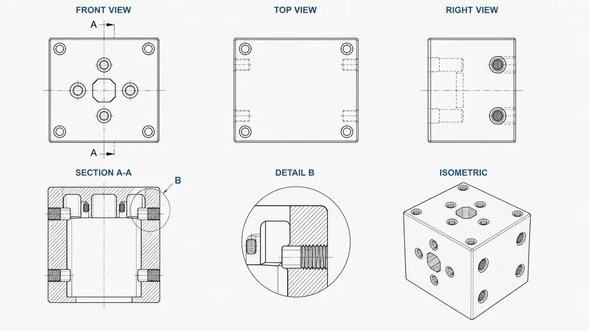
Choose views that let a supplier locate every required feature without reconstructing the design intent from hidden geometry. The drawing does not need a fixed number of views. It needs enough clear views to define the part and leave room for dimensions and callouts.
Orthographic Views
Orthographic views show the part from selected directions without perspective. Use the views that expose the main part shape, faces, holes, steps, slots, and other features a supplier must identify.
Place a dimension on the view that shows its feature. If a mounting face defines a hole pattern, show that face and the dimension origin together. Avoid adding the same controlled dimension in more than one view, because duplicate requirements can create conflicting acceptance conditions.
Section and Detail Views
Section and detail views clarify geometry that a standard exterior view cannot show cleanly. Use a section view when internal cavities, counterbores, wall transitions, or intersecting features would otherwise need hidden-line interpretation. Use a detail view when a small feature needs a larger scale for its callout.
Each extra view should resolve a specific ambiguity. A crowded sheet with repeated views can make a drawing harder to inspect, so add a view only when it gives the supplier information that the other views do not provide.
Reference Views
A reference or isometric view can help a supplier orient complex geometry, but it should not carry the controlling dimensions. Keep the dimensions and callouts on the orthographic, section, or detail view that defines the feature. This separation helps the drawing stay readable when a part has multiple faces or repeated features.
What Information Should the Drawing Control?
The drawing should control the information that changes how the supplier makes, finishes, measures, or accepts the part. Keep each requirement near the feature it affects when that placement makes the requirement clearer than a general note.
Part Identity and Revision
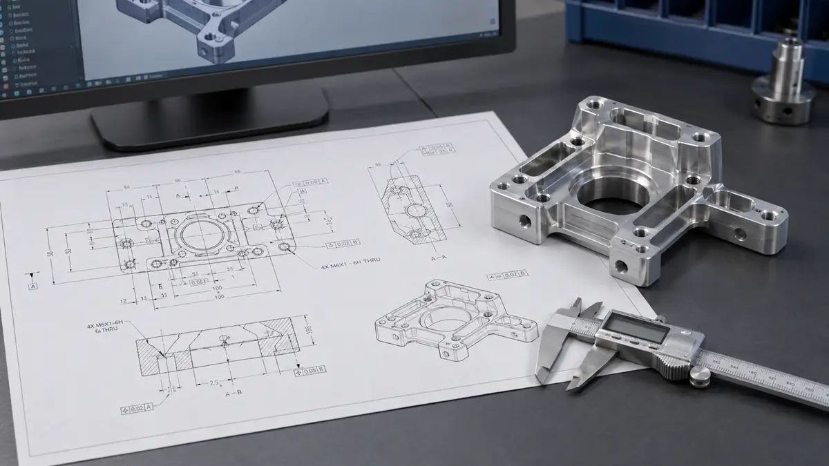
Identify the part number, drawing revision, units, and any document references that control the released part. The matching 3D model should carry the same part identity and revision so the supplier does not quote one version and machine another. If an approved change affects a functional feature, material, finish, or inspection requirement, update the controlled drawing and model together rather than leaving the requirement only in email or meeting notes.
Dimensions and Datums
Dimension the features that control fit, location, sealing, motion, alignment, or another stated function. Use a datum scheme when the relationship between features matters, because a size dimension alone may not define the required location or orientation.
Apply tighter requirements only where the part function needs them. The drawing should state the required tolerance or geometric control and the datum relationship when applicable. The supplier can then assess the machining and measurement plan against the same design intent.
Holes and Threads
Define a hole by its function and complete callout, not by a nominal diameter alone. The drawing should distinguish a clearance hole, locating bore, threaded feature, counterbore, countersink, or other controlled feature when that distinction affects machining or inspection.
For threads, identify the released designation, location, functional length, and blind or through condition. Add any project-specific requirement that affects the finished feature, such as a mating interface, a surface condition, or a required gauge or report. Tapped holes and threaded holes need different terminology, so do not assume that a model’s visible thread geometry communicates every acceptance requirement.
Materials, Finish, and Notes
State the material grade or approved alternative, then identify a finish or coating where it affects a functional surface, cosmetic area, or final dimension. When a finish changes the acceptance condition, the drawing should state whether the requirement applies before or after the finish and identify any masked or excluded areas. Use general notes for requirements that genuinely apply across the part, and put a local note on the related view when one surface, edge, or feature has a different requirement.
How Should the Drawing and 3D Model Work Together?
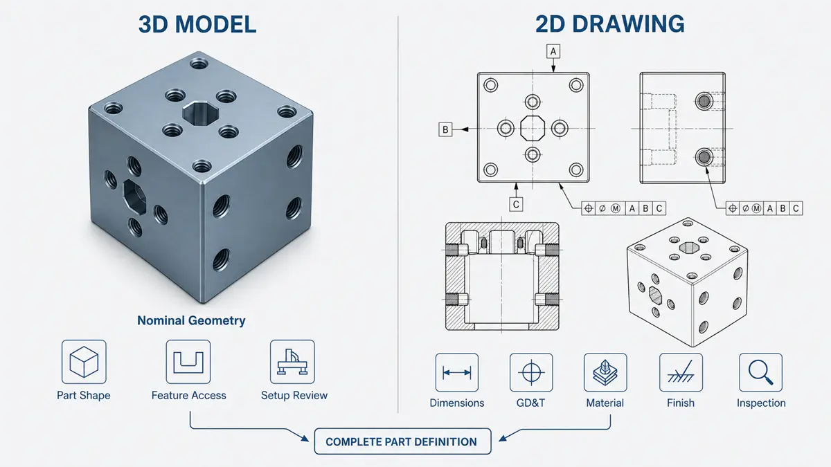
Use the 3D model to communicate nominal geometry and the technical drawing to communicate the released requirements that govern the part. The two files should support one product definition, not compete with each other.
Geometry and Requirements
The 3D model helps a supplier review part shape, machining access, and setup options. The drawing gives the supplier the dimensions, datums, feature callouts, material, finish, revision, and inspection requirements the supplier must follow or verify.
| Requirement | Where to state it | Supplier decision it supports |
|---|---|---|
| Nominal part geometry | 3D model, with supporting 2D views when needed | Toolpath, workholding, and setup review |
| Critical dimensions and datum relationships | 2D drawing | Machining references and measurement plan |
| Hole and thread callouts | 2D drawing | Feature method and inspection approach |
| Material and finished condition | 2D drawing and related specification | Material and finishing scope |
| Revision and required records | Controlled drawing and matched model revision | Quote scope and acceptance traceability |
The table does not assign every project detail to one universal file type. The same model can support a DFM review when the supplier must assess tool access, workholding, tolerance feasibility, or cost effects. When an approved model-based definition system controls a project, the buyer should state that control method and the information the supplier must use for acceptance.
Conflicting Revisions
Resolve a drawing and model conflict before a supplier releases a quote, program, or inspection plan. Identify the controlling revision in the package, correct the mismatch, and send the revised files together.
If a requirement changes after quotation, tell the supplier which feature changed and whether the material, finish, inspection record, or delivery scope also changed. This step keeps the team from confusing a commercial revision with a geometry change, or the reverse.
What Should You Check Before Sending the Drawing to a CNC Supplier?
Check that the drawing expresses the part’s function and acceptance requirements without assuming how the supplier will solve the manufacturing problem. A concise review can prevent the supplier from working from incomplete or conflicting information.
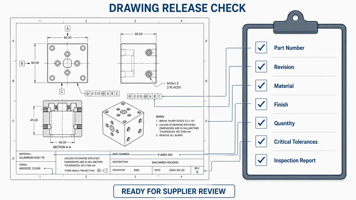
Functional Requirements
For custom CNC machining parts, mark the features that affect assembly, fit, sealing, location, movement, load transfer, or appearance. State the related dimensions, datums, materials, finishes, and mating information that explain why the feature matters.
Inspection Requirements
Identify the characteristics that need recorded results and state the required report or customer format when it affects acceptance. A drawing can define the dimension, datum, tolerance, or feature for inspection. The purchase or quality requirements should also make clear which party accepts a result and whether sampling, first article, or other documentation applies.
Match the inspection requirement to the part risk. CMM inspection can evaluate datum-based geometry, while other features may need different measurement tools. The drawing should identify the acceptance requirement without assuming that one instrument can verify every characteristic.
Supplier Review
Send the released drawing, matching 3D model, material requirement, finish, quantity, and project-specific inspection needs together. Ask the supplier to flag missing information or conflicts before machining begins.
Rollyu Precision can review CNC part drawings for DFM, tolerance, feature, and inspection questions before production, while the buyer retains responsibility for the released product definition and acceptance criteria.
Frequently Asked Questions
What Should I Do If the Drawing and 3D Model Do Not Match?
Stop the release and identify which document controls the part before the supplier quotes or starts work. Correct the mismatch, update the revision record, and send the drawing and model together. If a change affects a critical feature, confirm whether the inspection plan or report requirement also needs revision.
Can a CNC Supplier Quote a Part From a Partially Dimensioned Drawing?
A supplier can review a preliminary drawing, but the quote may need assumptions or exclusions when the missing information changes material, finish, tolerance, quantity, inspection, or revision scope. Mark the open items and ask the supplier which missing requirements prevent a firm quote. Release the completed controlled drawing before production begins.
Should a Technical Drawing Specify Tapping or Thread Milling?
Specify the finished thread requirement first, including the released designation, functional length, and acceptance condition. Add a process note only when a customer-controlled requirement, approved process, or project-specific qualification calls for a method. Otherwise, ask the supplier to review the feature and confirm a suitable machining method.
