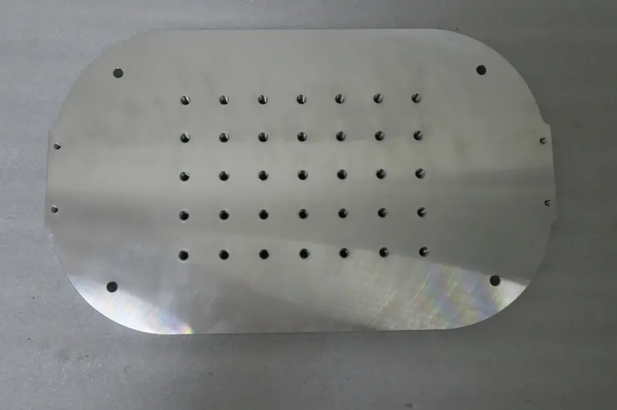
Use an off-the-shelf optical breadboard when its hole grid, outside dimensions, and mounting points fit your setup, and add an adapter if a single component needs a different interface. Choose a custom plate when the instrument needs its own locating features, cutouts, or attachment points. An optical breadboard is a mounting surface with a pattern of tapped holes for optical hardware. For a solid aluminum plate, the choice starts with where the components and the plate itself need to sit.
When to Use a Stock or Custom Plate
A stock grid leaves room to move lenses, mirrors, or stages while you settle the beam path. A custom plate makes sense once an enclosure, locating interface, or opening fixes where the hardware goes.
| Plate Option | Choose It When | Check Before Committing |
|---|---|---|
| Off-the-shelf plate | The regular grid fits your optical hardware and the plate fits the available space. | Compare the stock drawing with the hardware footprint and the plate’s own mounting points. |
| Stock plate with an adapter | One mount or stage uses a different hole pattern and the rest of the layout works. | Check added height, screw access, and clearance around the adapter. |
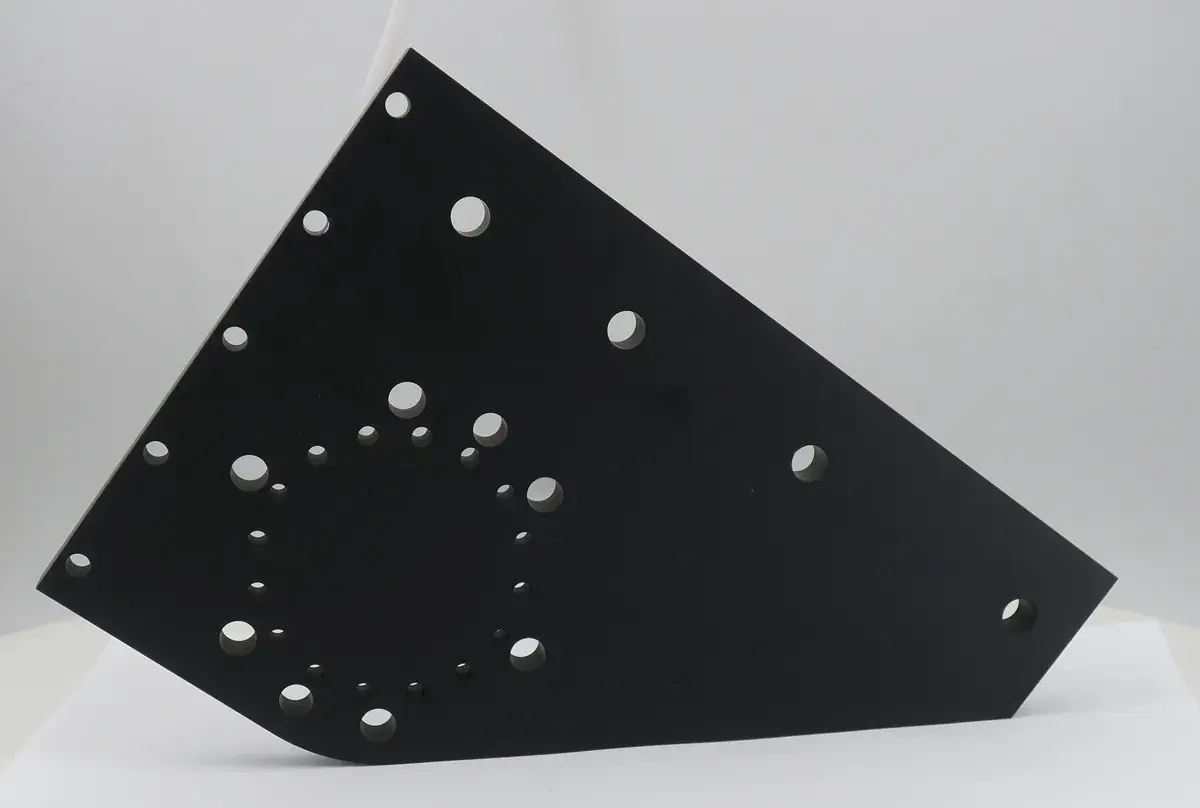
| Custom CNC-machined plate | The instrument needs a specific outline, locating holes, a cutout, or attachment points outside the stock grid. | Confirm what the plate locates and what it needs to clear before releasing the drawing. |
Consider a camera stage with a bolt pattern that misses the grid. If an adapter fits below the stage and still leaves enough height to set the optical axis, the stock plate remains a practical choice. When the added height moves the camera outside its adjustment range, mount the stage directly to a custom plate instead. A connector that passes through the chassis can also fix where an opening in the plate has to go.
Check the Mounting Layout Before You Order
Lay out the plate with the components and the frame in place, because a hole can line up on screen while a nearby bracket blocks access to the screw.
Thread and Hole Spacing
Check the thread and center-to-center spacing separately. Two common catalog patterns are 1/4-20 tapped holes on a 1-inch grid and M6 tapped holes on a 25 mm grid. An inch is exactly 25.4 mm, so the two grids drift apart by 0.4 mm per interval. A base with two fixed screw locations can therefore miss the second hole even when the first lines up. Check the mount drawing for the exact thread and spacing before selecting hardware.
Use the plate drawing to confirm usable thread depth and whether the holes are blind or through. In a blind hole, a screw that bottoms out can stop before the mount seats. For a screw that extends below the plate, check clearance to the frame or any hardware underneath, and use the screw length and thread engagement specified for the assembled joint.
Component Clearance and Plate Support
Place the full footprint of each optical mount on the layout, including knobs and the space needed to reach its screws. A mirror mount can fit on a row of holes and still leave too little room to turn an adjuster once the next component is installed. Check adjustment travel and installation access with the surrounding parts in position.
Then check the underside. The plate’s attachment holes and supports have to match the frame, posts, or work surface, and tightening the plate against supports of unequal height can pull it out of shape. When the layout depends on a common seating plane, carry the intended support arrangement into the drawing and inspection discussion.
What to Specify on a Custom Plate Drawing
Use a technical drawing to identify the interfaces that control assembly. The 3D model shows the geometry, while the drawing establishes which features locate the plate, which tolerances apply, and what condition the finished part has to meet.
Locating Features and Datums
Start at the instrument frame. If the underside seats on the frame and dowel holes locate the plate, use those functional features to establish the datum reference system. A datum is a reference used to define and check the position or orientation of other features. Dimension the critical mounting holes from those references so the plate, frame, and mounted components share a defined relationship. Locating and clamping are separate jobs: a close-fitting pin sets the location, and a screw clamps the parts together through a clearance hole. On the drawing:
- Call out locating holes separately from fastening holes.
- Show cable openings and the surfaces that support the plate.
- Set tighter tolerances on features that govern assembly or optical adjustment.
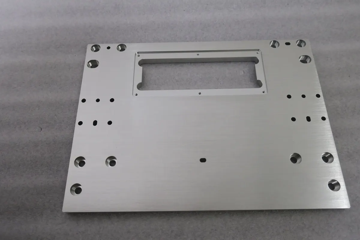
Flatness and Finish in the Right Condition
Flatness limits variation across a surface. Call out flatness on the seating surface that needs it, and if the top face also has to sit parallel to the underside, specify that relationship separately. Agree on where to support the plate during inspection, since a measurement on a free plate and one taken with the plate bolted down describe different conditions.
Identify the finished condition of close fits and seating faces. If the drawing calls for anodizing, mark any surfaces or threads that need masking and the dimensions that apply after finishing. A coordinate measuring machine (CMM) can then check surface geometry and hole positions in that condition, while a thread plug gauge checks the tapped threads.
How Rollyu Precision Reviews a Custom Plate
Rollyu Precision CNC machines aluminum baseplates and other mechanical components for photonics equipment. Ask for a design for manufacturability (DFM) review before you release the drawing.
DFM Review of Locating Features
A pocket near a locating hole gives the review a specific starting point. The team checks how much material the pocket leaves around the hole and whether the cutter can reach it in the proposed setup. Because Rollyu handles CNC machining and finishing in the same workflow, a locating hole that has to hold its fit after anodizing can be reviewed with the finish and masking callouts alongside the machined dimensions.
Inspection Records and Quote Package
For a pattern that mates to the instrument frame, agree on which hole locations and mounting faces the dimensional report should cover. Rollyu supports CMM inspection and first article inspection (FAI) documentation when the project calls for those records.
For a quote, send Rollyu Precision the 3D model and a matching 2D drawing with the material grade, finish, and quantity. Mark the features that control how the plate seats or where an optical mount lands, and identify the dimensions you want reported. If the prototype will go into a production instrument, include the expected production quantity so the team can review both stages.
Frequently Asked Questions
Can Two Optical Breadboards Share a Continuous Hole Grid?
Yes, when both boards use the same pitch and the rows line up. The two edge offsets plus the gap between the boards must add up to one grid interval. Check that distance against the mounting pattern of any component that spans the joint.
Does a Solid Optical Breadboard Isolate Vibration?
No. Vibration isolation comes from the support system under a solid breadboard. If vibration affects the experiment or instrument, choose an isolating support for the loaded assembly and check its performance with the equipment in place.
Sources
- How to Set Up an Optical Lab, Edmund Optics: Breadboard mounting and common inch and metric hole grids.
- Metric/English and English/Metric Adapter Plates, Edmund Optics: Adapters for mounting hardware across the two grid systems.
- SI Units for Length, NIST: The exact inch-to-millimeter conversion used to compare grid spacing.
- An Optical Frequency Reference Module with a Reproducible Layout, arXiv: A specific optical assembly built on a custom-machined aluminum plate.
- Locating and Clamping Principles, Carr Lane Manufacturing: How locating features, supports, and clamps constrain mechanical parts.
- Passive Vibration Isolation for Optical Tables, arXiv: A tested support system that isolates an optical table from mechanical vibration.