
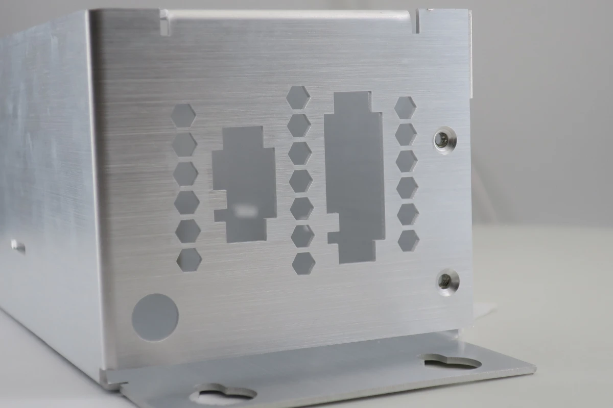

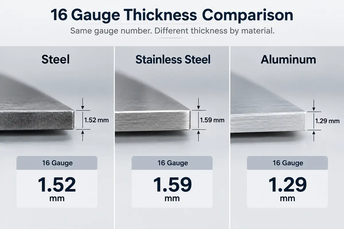
Material determines what thickness a sheet metal gauge number represents. For example, 16 gauge is 0.0598 in for standard steel, 0.0625 in for stainless steel, and 0.0508 in for aluminum. Reading the wrong column can change the specified thickness before a part reaches quoting or production.
Use the chart below to convert gauge to inches and millimeters. Then place the material grade, decimal thickness, and controlling unit on the drawing and RFQ so the engineering model and supplier quote describe the same sheet.
Sheet Metal Gauge Chart in Inches and Millimeters
This sheet metal gauge chart lists nominal reference thicknesses for standard steel, stainless steel, and aluminum. The table converts the inch values to millimeters at 25.4 mm per inch and rounds the results for display.
| Gauge | Steel (in) | Steel (mm) | Stainless Steel (in) | Stainless Steel (mm) | Aluminum (in) | Aluminum (mm) |
|---|---|---|---|---|---|---|
| 3 | 0.2391 | 6.07 | 0.2500 | 6.35 | 0.2294 | 5.83 |
| 4 | 0.2242 | 5.69 | 0.2344 | 5.95 | 0.2043 | 5.19 |
| 5 | 0.2092 | 5.31 | 0.2188 | 5.56 | 0.1819 | 4.62 |
| 6 | 0.1943 | 4.94 | 0.2031 | 5.16 | 0.1620 | 4.11 |
| 7 | 0.1793 | 4.55 | 0.1875 | 4.76 | 0.1443 | 3.67 |
| 8 | 0.1644 | 4.18 | 0.1719 | 4.37 | 0.1285 | 3.26 |
| 9 | 0.1495 | 3.80 | 0.1563 | 3.97 | 0.1144 | 2.91 |
| 10 | 0.1345 | 3.42 | 0.1406 | 3.57 | 0.1019 | 2.59 |
| 11 | 0.1196 | 3.04 | 0.1250 | 3.18 | 0.0907 | 2.30 |
| 12 | 0.1046 | 2.66 | 0.1094 | 2.78 | 0.0808 | 2.05 |
| 13 | 0.0897 | 2.28 | 0.0938 | 2.38 | 0.0720 | 1.83 |
| 14 | 0.0747 | 1.90 | 0.0781 | 1.98 | 0.0641 | 1.63 |
| 15 | 0.0673 | 1.71 | 0.0703 | 1.79 | 0.0571 | 1.45 |
| 16 | 0.0598 | 1.52 | 0.0625 | 1.59 | 0.0508 | 1.29 |
| 17 | 0.0538 | 1.37 | 0.0563 | 1.43 | 0.0453 | 1.15 |
| 18 | 0.0478 | 1.21 | 0.0500 | 1.27 | 0.0403 | 1.02 |
| 19 | 0.0418 | 1.06 | 0.0438 | 1.11 | 0.0359 | 0.91 |
| 20 | 0.0359 | 0.91 | 0.0375 | 0.95 | 0.0320 | 0.81 |
| 21 | 0.0329 | 0.84 | 0.0344 | 0.87 | 0.0285 | 0.72 |
| 22 | 0.0299 | 0.76 | 0.0313 | 0.79 | 0.0253 | 0.64 |
| 23 | 0.0269 | 0.68 | 0.0281 | 0.71 | 0.0226 | 0.57 |
| 24 | 0.0239 | 0.61 | 0.0250 | 0.64 | 0.0201 | 0.51 |
| 25 | 0.0209 | 0.53 | 0.0219 | 0.56 | 0.0179 | 0.45 |
| 26 | 0.0179 | 0.45 | 0.0188 | 0.48 | 0.0159 | 0.40 |
| 27 | 0.0164 | 0.42 | 0.0172 | 0.44 | 0.0142 | 0.36 |
| 28 | 0.0149 | 0.38 | 0.0156 | 0.40 | 0.0126 | 0.32 |
| 29 | 0.0135 | 0.34 | 0.0141 | 0.36 | 0.0113 | 0.29 |
| 30 | 0.0120 | 0.30 | 0.0125 | 0.32 | 0.0100 | 0.25 |
The chart values are nominal. Actual sheet thickness can vary within the limits of the applicable material specification and purchase order, so a chart value alone is not an acceptance tolerance.
Why the Same Gauge Has Different Thicknesses
The same gauge number has different thicknesses because standard steel, stainless steel, and aluminum use different gauge series. Standard steel follows the Manufacturers’ Standard Gauge, stainless steel has a separate sheet series, and aluminum commonly uses the Brown & Sharpe series.
Gauge is also an inverse scale. A lower gauge number represents thicker sheet within the same material column. Cross-material comparisons still require the decimal thickness because 16 gauge stainless steel is thicker than 16 gauge standard steel, while 16 gauge aluminum is thinner than both. The gauge label also does not distinguish hot-rolled from cold-rolled steel, so the material specification still needs to identify the required steel product.
How Actual Thickness Affects a Sheet Metal Part
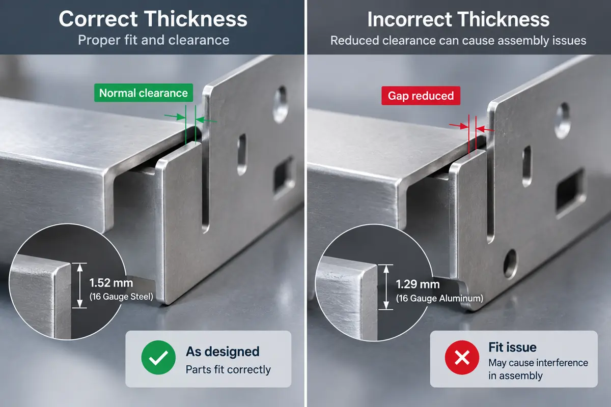
Actual thickness affects part weight, the forming setup, and the location of mating surfaces. The sheet metal fabrication process uses the specified material and thickness as inputs to cutting and forming, so a gauge conversion error can move beyond the material note and show up in the assembly.
Part Weight
For the same alloy and cut area, sheet weight rises in direct proportion to thickness. Replacing 16 gauge aluminum with 16 gauge standard steel changes both the thickness and the material density, so a gauge-only comparison cannot predict the weight change.
Mass calculations need the decimal thickness and density of the selected alloy. The gauge number alone does not provide either value across different materials.
Bending Setup
Material thickness is one input to bend radius, minimum formed-edge length, tooling, and flat-pattern development. A thickness change can require a different forming setup and can change the finished formed-feature location even when the nominal bend angle stays the same.
This page does not calculate bend allowance or K-factor. Keep the CAD model, drawing thickness, and fabrication review on the same decimal value.

Assembly Fit
Thickness changes can shift an inside or outside surface when the design uses the opposite face as its datum. That shift can alter enclosure clearance, bracket spacing, fastener reach, or the position of a mating panel.
Check the thickness stack wherever a formed face locates another part. If fit depends on the delivered material rather than the nominal chart value, define the relevant acceptance limit in the drawing or purchasing requirements.
How to Specify Thickness on a Drawing and RFQ
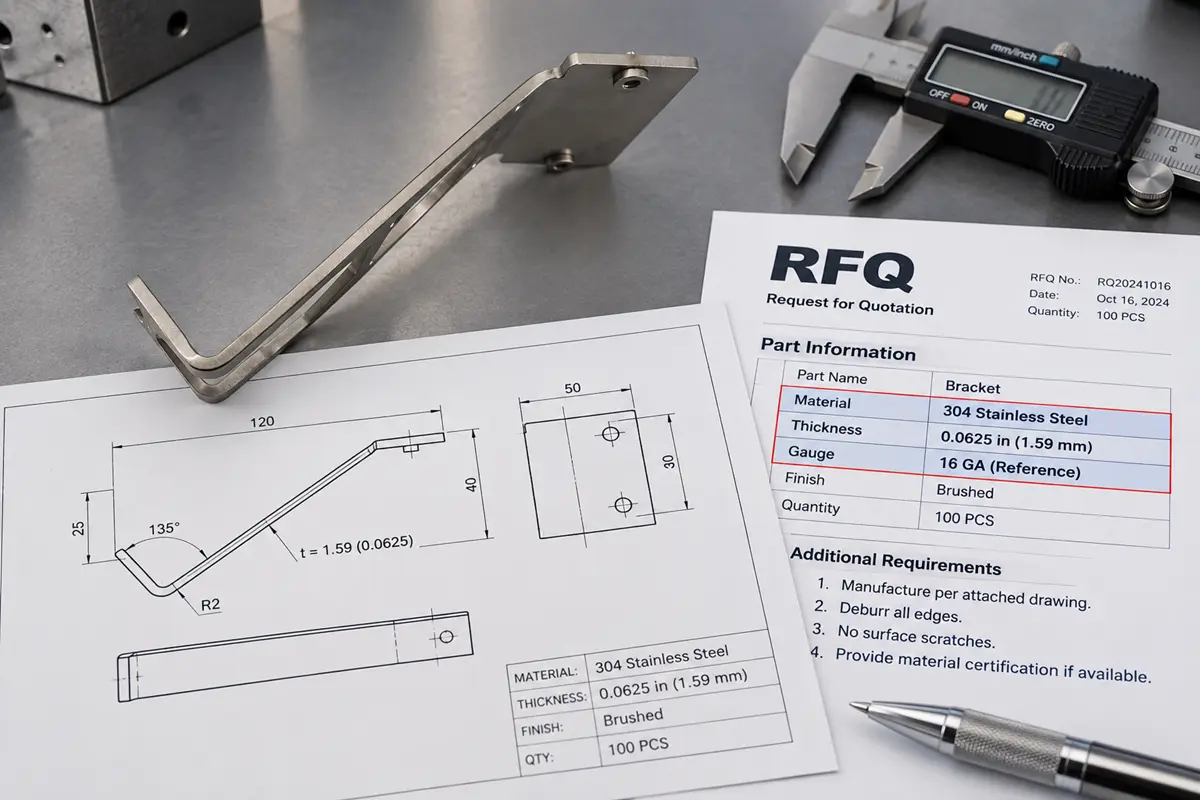
Specify the material and decimal thickness together, then identify one controlling unit. A clear callout can read 304 stainless steel, 0.0625 in nominal thickness or 5052-H32 aluminum, 1.29 mm nominal thickness.
Include the following information when it affects the part:
- Material family and grade.
- Nominal decimal thickness and controlling unit.
- Gauge as an optional secondary reference.
- The applicable thickness tolerance, material specification, or purchase-order limit when fit depends on delivered thickness.
If inches and millimeters both appear, mark one value as reference. Independent rounding can otherwise create two slightly different acceptance values. The 3D model, 2D drawing, and RFQ should use the same controlling thickness. Keep broader sheet metal fabrication design decisions in a separate DFM review so the gauge callout remains unambiguous.
Sheet Metal DFM and Quote Review
A fabrication review with Rollyu Precision can compare the requested material, grade, decimal thickness, bend geometry, and assembly interfaces before the supplier releases the quote. This check is especially useful when an older drawing lists only a gauge number or when an inch-based model moves into a metric supply chain.
Send the revision-matched CAD file and drawing with the material grade, thickness, quantity, finish, and critical fit requirements. Those inputs identify the part revision and the acceptance basis for the engineering review.
Rollyu Precision’s sheet metal fabrication service includes laser cutting, press-brake bending, welding, and deburring. The DFM and quote review can focus on the intended material and part geometry before manufacturing starts.
