


Laser kerf size is the physical width of material removed by a focused cutting beam. Because optical dynamics, assist gas pressures, and raw material alloys continuously interact on the shop floor, no universal reference chart can reliably predict this cut width across every job. Achieving repeatable tab-and-slot fit requires decoupling beam kerf compensation from mechanical joint clearance, modeling nominal 1:1 geometry in CAD, and verifying physical fit on stepped test cuts. Treating programmed cut lines as finished joint boundaries produces binding tabs, loose joints, and expensive secondary grinding during assembly.
Why Laser Kerf Size Varies Across Sheet Metal Cuts
Industrial laser cutting focuses optical energy onto a concentrated spot to melt or vaporize metal, using a high-pressure assist gas jet to eject the molten pool through the bottom of the plate. The resulting cut channel varies whenever optical focus, motion dynamics, or alloy compositions change.
Beam Focus and Optical Parameters
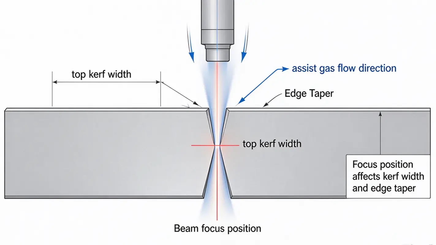
Kerf width follows the hourglass profile of the focused beam waist. In industrial fiber and CO2 laser systems, focusing optics concentrate raw beam energy into a spot diameter typically spanning 0.05 mm to 0.40 mm, depending on fiber core diameter, collimation ratio, and focal length.
Focus position relative to the sheet surface dictates the cut wall profile and kerf taper. For thin sheet nitrogen cutting, positioning the focal point near the top surface concentrates peak power density at the beam entrance, creating a narrow entry channel that diverges slightly toward the bottom. For thicker plates, moving the focal point deeper into the material or near the bottom surface widens the lower kerf exit. This widening provides the mechanical clearance necessary for the assist gas jet to flush heavy dross out of the cut zone without gouging the side walls. Minor deviations in nozzle orifice diameter, nozzle-to-plate standoff height, or protective window centering immediately shift this thermal profile, altering the cut width between shifts.
Cutting Speed and Assist Gas Dynamics
Machine feed rate determines laser energy interaction time per unit length. Slow cutting speeds allow excess heat to conduct laterally into the surrounding parent metal, causing side-burning, gouging, and wider cut channels in carbon steel and aluminum. Higher speeds narrow the kerf by limiting lateral heat conduction, but pushing traverse rates too high leads to heavy striations, loss of squareness, or incomplete bottom penetration.
Assist gas selection shifts the cutting mechanism between chemical reaction and pure fluid mechanics:
- Oxygen cutting: Oxygen reacts exothermically with iron in carbon steel, adding chemical heat that accelerates cutting speeds but burns a wider, slightly oxidized kerf channel.
- Nitrogen fusion cutting: High-pressure nitrogen serves as an inert mechanical shield. The laser provides 100% of the thermal melting energy, while nitrogen pressure (often 12 to 20 bar) blows molten metal cleanly through the kerf, yielding a narrower cut path with unoxidized, weld-ready edges.
Material Grade and Thermal Dissipation
Alloy composition and sheet thickness govern how heat conducts away from the beam impact zone. Highly reflective alloys with high thermal conductivity, such as copper and aluminum 6061, dissipate thermal energy rapidly into the surrounding sheet, demanding higher optical power density to sustain a stable melt pool. In contrast, austenitic stainless steel retains localized heat, leading to sustained localized melt zones. Thicker plates also require larger nozzle diameters and extended optical Rayleigh lengths to maintain beam concentration through the cut depth, naturally increasing the baseline kerf width.
How to Measure Kerf Width on a Test Cut
Before programming toolpath offsets for production sheets, manufacturing engineers verify beam kerf directly on physical test coupons using the identical machine, cutting optics, assist gas settings, and material batch allocated to the final build.
Measuring a Single Geometric Coupon
The single-feature test uses a straightforward geometric shape, such as a 20.00 mm square or a precision slot, cut directly on representative scrap stock:
- Program the CNC laser controller to cut a 20.00 mm square profile directly on the vector path without applying toolpath kerf compensation (G40 mode).
- Remove the detached coupon and scrape any bottom dross off the lower perimeter with a flat scraper, taking care not to file or round the vertical edge.
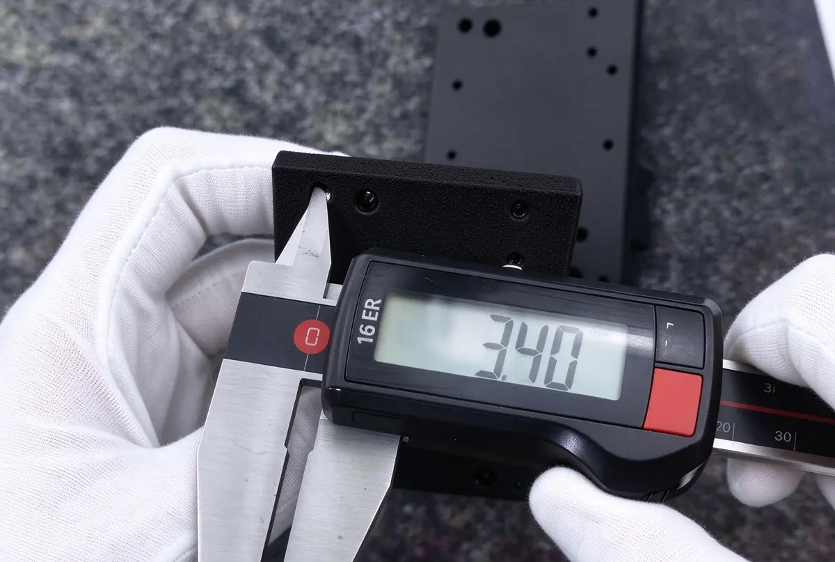
- Measure the exterior width across multiple points using a calibrated micrometer.
The calculation uses the difference between the programmed path and the physical part:
- Kerf Width = Nominal Vector Dimension – Measured Feature Dimension
Because the laser beam centerline travels directly along the programmed 20.00 mm vector, half of the beam kerf burns into the scrap skeleton, while the other half cuts into the interior of the test part. If the physical coupon measures 19.82 mm, the total kerf width is 0.18 mm (20.00 mm – 19.82 mm), establishing a toolpath offset radius of 0.09 mm. When evaluating an internal slot, the calculation inverts: the internal opening measures larger than nominal by the width of one full kerf. While quick, single-feature coupons can introduce small gauge errors if caliper anvils rest over lead-in marks or localized heat distortion.
Averaging Across Multiple Cuts with a Parallel Strip Nest
The slotted comb or parallel strip test yields higher measurement repeatability by spreading kerf measurement across ten or twenty adjacent cuts, filtering out operator caliper error:
- Program a shared rectangular frame containing ten identical strips, each programmed at 10.00 mm wide, cut with production feed and gas settings under zero toolpath offset.
- Remove the loose strips from the sheet skeleton and clean bottom burrs from the lower edges.
- Push all ten cut strips tight against one side of the internal skeleton frame.
- Measure the total accumulated gap remaining between the final strip and the opposing interior frame wall using feeler gauges or calipers.
- Divide the total accumulated gap width by the total number of cut lines (eleven cut passes for ten nested strips bounded by the frame) to derive average kerf per pass.
Averaging across multiple cuts captures minor directional variations between the X-axis and Y-axis gantry drives while delivering a dependable baseline for CAM programming.
Where Kerf Compensation Occurs in the CAD-to-CAM Workflow
Clarifying where dimensional compensation takes place prevents double-offset errors between mechanical design models and machine toolpaths.
Separating Nominal Part Geometry from CAM Offsets
Design Engineers and detailing teams must define nominal 1:1 finished geometry on CAD models and 2D fabrication drawings. Keeping CAD geometry true to size aligns part models with standard sheet metal fabrication design guidelines and preserves functional design intent regardless of which cutting machine handles the job.
Kerf compensation belongs exclusively in CAM nesting software or the machine’s CNC controller. During nesting, the programmer inputs the measured half-kerf value as a tool radius offset (analogous to G41/G42 cutter radius compensation in CNC milling). The CAM post-processor automatically shifts the beam path outward along external perimeters and inward along internal cutouts. If an engineer manually enlarges a slot or shrinks a tab inside a 3D CAD model to account for kerf, and the machine programmer subsequently applies standard CAM kerf offset, the cut profile suffers double compensation, ruining part tolerances.
Dimensional Drift in Uncompensated Cuts
To evaluate why automated toolpath compensation is essential, consider the geometric shift that occurs when a laser cuts directly along nominal geometry without an offset, assuming a typical kerf width of 0.20 mm (0.10 mm removed on either side of the beam center):
- Exterior Tab: A tab modeled at 10.00 mm loses 0.10 mm per side. The finished physical tab measures 9.80 mm.
- Interior Slot: A mating slot modeled at 10.00 mm loses 0.10 mm per interior edge. The finished physical opening expands to 10.20 mm.
- Joint Clearance Shift: Two mating components modeled for line-to-line contact (0.00 mm clearance) yield an unintentional clearance gap of 0.40 mm (10.20 mm – 9.80 mm), quadrupling the planned joint play.
Why Accurate Kerf Measurements Do Not Guarantee Tab-and-Slot Fit
Dialing in kerf compensation ensures individual cut features match their nominal 2D profile. However, successful tab-and-slot engagement depends on physical manufacturing boundaries that toolpath offsets cannot resolve.
Decoupling Cut Edge Tolerances from Sheet Rolling Tolerances
Tab-and-slot joints involve two independent physical interfaces governed by different manufacturing processes:
- Tab Width vs. Slot Length: Both profiles are laser-cut features. Fit along this axis is determined by CNC positioning accuracy, kerf consistency, and edge squareness.
- Tab Thickness vs. Slot Width: This interface inserts the raw, mill-rolled sheet thickness into a laser-cut slot opening.
Commercial sheet metal exhibits thickness variations under mill rolling standards like ASTM A480 for stainless steel and ASTM B209 for aluminum. A sheet purchased as nominal 2.0 mm cold rolled steel often measures 1.92 mm on one edge and 2.06 mm on the other, as reflected in standard sheet metal gauge charts. If a slot width is programmed tightly around 2.00 mm, a tab cut from a thicker section of the sheet will bind during assembly regardless of how accurately the laser kerf was calibrated.
Accounting for Cut Edge Taper
Laser cut walls are not perfectly perpendicular planes. Depending on focal position and material thickness, the cut channel exhibits edge taper ranging from 0.5 degrees to 2.0 degrees. In a 3.0 mm stainless steel plate, a 1.0 degree taper per cut face reduces the slot clearance by approximately 0.10 mm across the bottom face relative to the top entrance. If tabs are inserted from the narrow exit side, they will wedge prematurely against the tapered sidewall.
Finishing Allowances and Secondary Operations
Secondary fabrication processes directly alter the physical clearance of mating tabs:
- Deburring and Edge Blending: Mechanical tumbling or graining performs necessary part deburring to strip micro-burrs and edge dross. However, uncontrolled manual edge breaking or aggressive wheel grinding rounds the tab shoulders, creating joint rock along structural datum faces.
- Surface Coating Build-Up: Powder coating deposits 0.05 mm to 0.08 mm (50 to 80 microns) of cured polymer per side. Because coating covers both exterior tab walls (adding 0.10 mm to 0.16 mm to tab thickness) and internal slot faces (reducing slot opening by 0.10 mm to 0.16 mm), an assembly loses 0.20 mm to 0.32 mm of total joint clearance after coating unless tabs and slots are masked prior to curing.
- Press Brake Bending Distortion: When tabs or slots sit close to bend lines, plastic deformation in the bend zone pulls slot sidewalls out of square, pinching the slot opening unless the flat pattern incorporates appropriate bend relief notches.
Verifying Tab-and-Slot Fit Through Physical Trial Assembly
Because kerf compensation and assembly clearance serve two distinct engineering functions, development teams validate mechanical engagement through stepped clearance coupons before releasing production runs.
Stepped Clearance Coupons for Tactile Fit Testing
In precision sheet metal fabrication, cutting a stepped test coupon alongside the production nest confirms the tactile assembly feel on actual sheet stock. Design a single test coupon featuring five slots with opening widths stepped in 0.05 mm increments (such as nominal gauge + 0.05 mm, + 0.10 mm, + 0.15 mm, + 0.20 mm, and + 0.25 mm). Inserting a test tab cut from the identical production sheet identifies the exact clearance required for the target assembly method.
| Assembly Objective | Empirical Total Clearance Range | Dominant Physical Influence | Shop Floor Verification Action |
|---|---|---|---|
| Loose Slip Fit (Fast manual alignment prior to welding) | 0.20 mm to 0.35 mm | Cut edge taper, heat distortion, weld penetration access | Insert tab by hand; confirm unrestricted positioning along the joint without catching on edge striations. |
| Snug Hand-Push Fit (Self-fixturing assembly without clamps) | 0.08 mm to 0.15 mm | Mill thickness tolerance, cut edge taper | Seat tab with firm thumb pressure; verify self-squaring along mating reference shoulders. |
| Light Press Fit (Friction retention for unpainted chassis) | 0.02 mm to 0.06 mm | Micro-burrs, sheet thickness runout, machine positioning | Seat tab using a dead-blow mallet; check slot corners for micro-cracking or localized bulging. |
| Coated Assembly (Post-cut powder coat or e-coat) | 0.25 mm to 0.45 mm | Cured coating film thickness on internal and external faces | Test-fit pre-coated samples, or verify custom masking plugs on bare test coupons. |
Production Handoff and Fit Confirmation with Rollyu
When releasing sheet metal weldments and enclosures for manufacturing, Mechanical Engineers and sourcing teams should supply 1:1 nominal CAD models alongside 2D drawings that specify critical slot datum faces, expected fit class, and post-coating requirements.
Partnering with Rollyu Precision pairs automated DFM geometry review with empirical test cuts on production-matched material stock to confirm tab-and-slot alignment before volume cutting begins. While precision CNC milling regularly holds tolerances down to +/-0.005 mm, sheet metal laser cutting operates under different physical constraints. Rollyu balances machine positioning, gas selection, and controlled joint clearances to deliver rigid, self-fixturing sheet assemblies that weld clean without manual rework.
Frequently Asked Questions
How do internal slot corner radiuses affect tab seating?
Internal corner fillets prevent rectangular tabs from seating flush by interfering with the tab shoulder. Because the laser leaves a radius equal to half the kerf (typically 0.04 mm to 0.15 mm), engineers resolve this interference by adding 0.5 mm dog-bone relief notches at slot corners or chamfering the mating tab tips.
Where should laser lead-in pierce points be positioned on tab-and-slot profiles?
Laser lead-in pierce points must be placed on exterior scrap areas or non-contact shoulder edges, never on functional mating faces. Piercing generates localized slag spatter and entrance divots that act as high spots, jamming mating tabs and pulling assemblies out of square.
What is the minimum recommended slot width for laser-cut sheet metal?
The minimum recommended laser-cut slot width equals the nominal sheet thickness (1.0 x T). Cutting slots narrower than stock thickness traps excessive cutting heat, causing thermal blowouts, severe edge taper, and heavy dross buildup that chokes the slot opening. In plates over 3.0 mm thick, sub-thickness slots often require secondary milling to achieve parallel sidewalls.
