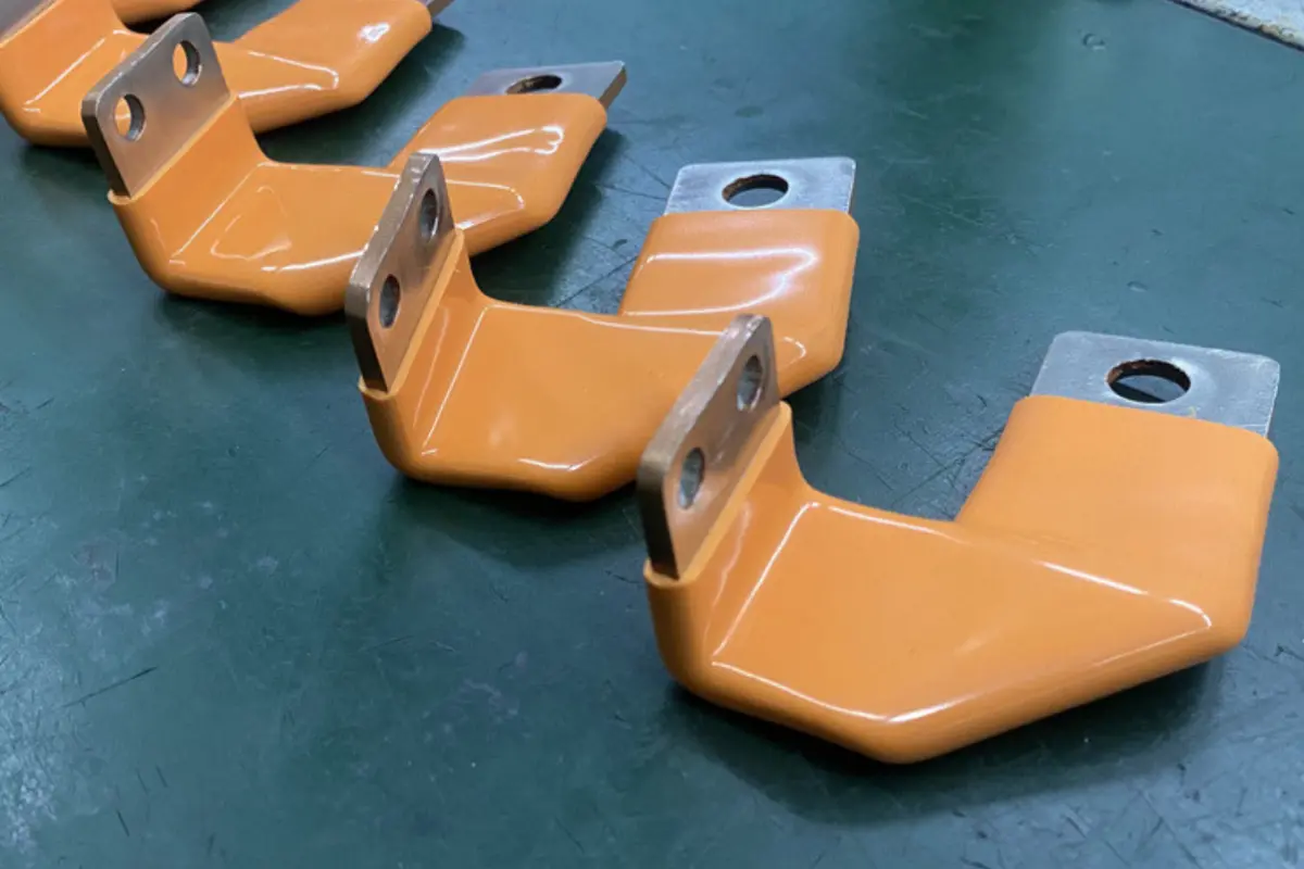
Design a custom copper busbar so the drawing matches the cutting, forming, and finishing limits of the process that will make it. Flat and bent spans usually belong in sheet metal fabrication, while thick stepped blocks and precision contact pads belong in CNC machining.
Electrical Sizing vs. Mechanical Design
Electrical engineers size a copper busbar for continuous current, allowable temperature rise, short-circuit forces, and creepage and clearance distances. Cross-sectional area sets the DC resistance, and a wider, thinner bar exposes more surface for cooling. Mersen’s busbar guide recommends a width at least three times the thickness. Mechanical engineers then turn those dimensions into a manufacturable drawing without changing the conductive area or the clearances, setting bend radii, hole positions, and pad flatness from forming and machining limits.
Copper Grades and Tempers
Choose the alloy and temper before the manufacturing route, because both change conductivity, bend behavior, and machinability.
C11000, C10100, and C14500 Compared
| Alloy | Copper Content | Conductivity | Machinability Rating | Typical Busbar Use |
|---|---|---|---|---|
| C11000 (electrolytic tough pitch) | 99.90% min. | 101% IACS (100% min. annealed) | 20 | Most flat and bent power distribution bars |
| C10100 (oxygen-free electronic) | 99.99% min. | 101% IACS min. (annealed) | 20 | Brazed, welded, or vacuum assemblies |
| C14500 (tellurium copper) | 99.90% min., with 0.40-0.7% Te | 93% IACS | 85 | Thick blocks with tapped grids, turned contacts, or pockets |
C11000 suits most busbars, but its small oxygen content makes the alloy prone to hydrogen embrittlement when heated in a reducing atmosphere during welding or brazing. The Copper Development Association (CDA) busbar guide links this reaction to porosity and intergranular cracking. Oxygen-free C10100 or C10200 avoids that risk. C14500 gives up 8 points of conductivity (93% versus 101% IACS) for short, broken chips and a machinability rating of 85 against 20, which suits blocks that need extensive copper CNC machining.
Temper and Grain Direction
Copper strip and bar come annealed (O60) or cold-rolled to tempers such as H01 quarter hard, H02 half hard, and H04 hard. Annealed stock bends around tight radii with less force, but it smears on milling cutters and leaves heavy burrs around drilled holes. Half-hard bar, which Watteredge lists as the standard busbar temper, holds machined flatness and thread strength better and still bends well when the bend line runs across the rolling direction. Tight bends parallel to the rolling direction can crack the stretched outer surface and need a larger radius.
Sheet Metal vs. CNC Machining for Copper Busbars
Choose the route by bar thickness, pad geometry, and which features carry tight tolerances, rather than by unit volume alone.
| Manufacturing Route | Geometry | What the Route Controls Well | Watch For |
|---|---|---|---|
| Sheet metal fabrication (laser cutting, punching, press brake) | Uniform flat or bent bars | Cut profiles, hole patterns on flat stock, and bends | As-rolled flatness at contact pads, and cut-edge burrs that need deburring before bolting |
| CNC machining (3-, 4-, and 5-axis, plus wire EDM) | Thick bars, stepped pads, counterbores, and blocks | Machined contact faces, bores, tapped holes, and sharp EDM cutouts | Material removal cost on long or bent shapes |
| Formed bar with CNC-machined pads | Bent bars that need aligned holes across bends or coplanar terminals | Spans at sheet metal tolerances, with pads and hole patterns machined after bending | Second-operation fixturing for the formed part |
The hybrid route suits a power module that needs long L-shaped or Z-shaped copper runs with one precision mounting pad. The blank goes through custom sheet metal fabrication to laser-cut and bend the profile. The formed part is then clamped in a CNC fixture to skim-mill the bolted pad, drill datum holes, and form-tap critical threads.
Bending Rules for Copper Busbars
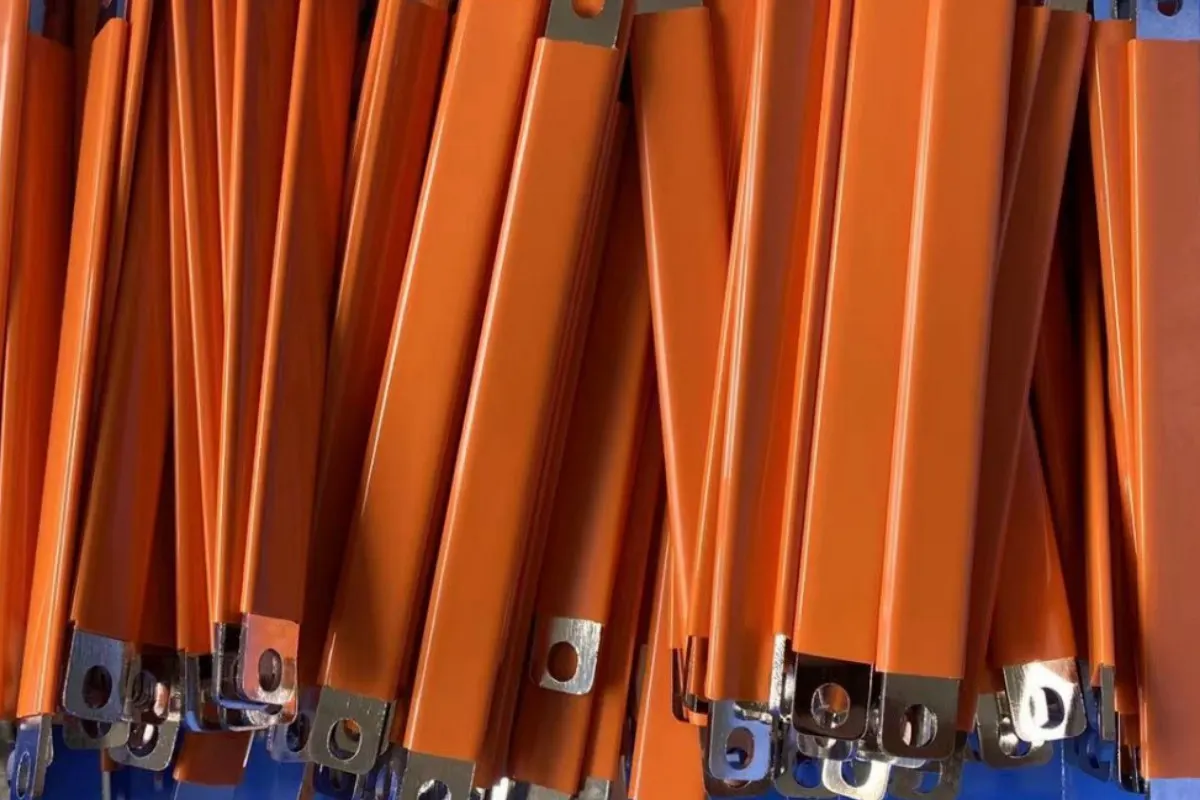
Copper work-hardens as it bends, and forming strain can pull nearby holes and flanges out of position. Set bend radii, reliefs, and feature clearances in CAD before the flat pattern is released.
Bend Radius, Relief, and Springback
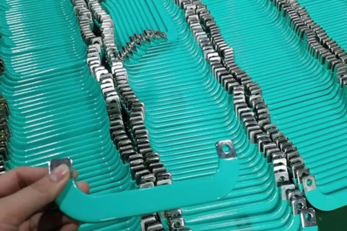
The CDA guide sets minimum inside bend radii for half-hard or hard copper by bar thickness (t): 1t up to 10 mm, 1.5t from 11 to 25 mm, and 2t from 26 to 50 mm. It notes that bars thicker than 50 mm are not normally bent without local annealing. Add a bend relief wherever a bend ends beside an unbent tab, following sheet metal bending design rules for relief size. Springback and bend deduction change with temper, thickness, and die opening. Ask the fabricator to confirm both with test bends in the actual copper before cutting a production batch.
Hole, Edge, and Flange Spacing
Holes cut inside the bend’s stretch zone turn oval, and short legs drop into the V-die opening during forming. Use these common sheet metal starting values, where t is thickness, and confirm them against the fabricator’s copper tooling:
- Hole diameter of at least 1t, which protects punches and keeps small holes clean
- At least 2t from a hole to the bar edge or to the next hole
- At least 2t from a hole to the bend tangent, or drill critical mounting holes after forming
- A formed leg at least 3t long from the bend tangent, long enough to bridge both shoulders of the V-die
Machining Rules for Thick Bars and Pads
Pure copper is gummy to machine: it grabs cutting edges, builds burrs, and can shift in the vise. Corner radii, wall thickness, and tapping method all need to account for that behavior.
Corners, Walls, and Fixturing
Give milled pockets and stepped shelves internal corner radii that standard end mills can cut, and reserve wire EDM for sharp internal corners or narrow slots a rotating cutter cannot reach. Keep walls thick and pockets shallow where function allows, because thin copper walls and deep, narrow pockets deflect under cutting force. On asymmetric or bent parts, provide flat, parallel faces or sacrificial tabs so the machinist can clamp the bar without twisting the contact zones.
Tapping and Burr Control
Cut taps can drag stringy chips through C11000 and C10100 threads and break in blind holes. Form taps suit these ductile grades because they displace metal into chip-free threads, though they need a larger pilot hole than a cut tap. C14500 works with sharp, high-rake carbide tools and standard cut taps. On every bolted terminal hole, call out an edge break and a burr limit, because a raised burr holds the mating lug off the contact face and reduces the contact area.
Bolted Joints and Contact Faces
A bolted joint carries current through the metal-to-metal contact area under the bolt, and bar camber or press-brake die marks shrink that area. The CDA guide notes that joint overlaps often run much longer than five times the bar thickness to leave room for the bolts. On wider bars, its typical single-face overlap roughly equals the bar width. The guide calls for flat contact surfaces roughened just before assembly. It prefers joint pressures above 10 N/mm², advises against anything below 7 N/mm², and reports little further drop in contact resistance above about 30 N/mm².
Put flatness and roughness callouts on the bolted pads and on surfaces that locate semiconductors, dowel pins, or insulating housings. Open-air spans can stay at sheet metal or bar stock tolerances, which cuts fixture changes, probing, and scrap without affecting electrical function.
Busbar Plating and Masking
Copper-to-copper bolted joints do not normally need plating. The CDA guide explains that copper oxide films form slowly and stay semiconducting. It recommends plating contact areas only when the environment calls for corrosion protection, partly because a soft plating can flow and reduce contact pressure. Each plating also has limits: pure tin can grow whiskers, and nickel needs high joint pressure because its oxide is tough. Silver works well but costs more and tarnishes where sulfur compounds are present. Bare copper in humid or contaminated cabinets also needs oxidation control before assembly.
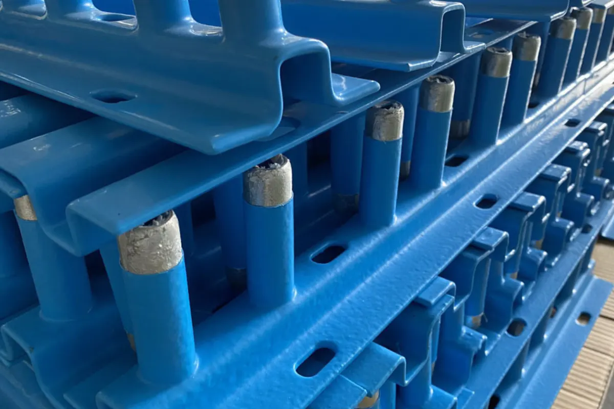
Plate after cutting, bending, and machining where assembly fit allows, because forming can crack a hard electroplated layer. Mask tapped holes or allow for plating thickness in the thread size, and use zone callouts to keep plating off insulated spans and powder coating off bolted contact pads. Rollyu Precision’s listed finishes include nickel, zinc, and chrome electroplating, electroless nickel, black oxide, powder coating, brushing, polishing, bead blasting, and laser marking. Confirm tin or silver plating, epoxy or film insulation, masking fixtures, and thickness acceptance criteria during quoting.
Quote Preparation and Inspection
Send the drawing package and inspection requirements together. The supplier can then check tooling clearances, bend allowances, and finishing sequence in the first review.
Inspection and Traceability Records
Material traceability starts with Material Test Reports (MTRs) that confirm the UNS grade, temper, chemistry, and heat lot before cutting begins. Rollyu Precision states that its quality management system is certified to ISO 9001:2015 and ISO 13485:2016, and it combines DFM review at quotation with in-process and pre-shipment inspection. Rollyu’s inspection equipment includes coordinate measuring machines (CMMs), optical comparators, height and pin gauges, thread gauges, surface roughness testers, and coating thickness testers. The company can supply first article inspection (FAI) reports, Certificates of Conformance (CoCs), and lot traceability records, plus RoHS and REACH declarations where the materials and finishes support them.
Keep this dimensional and material evidence separate from electrical verification. Millivolt-drop joint tests, temperature-rise runs, and dielectric (hipot) tests need an assigned owner on the purchase order, because a mechanical fabrication order does not include them by default.
RFQ Package Checklist
Include these items with every copper busbar quote request:
- A 3D STEP model and 2D PDF drawing with functional datums, tapped hole callouts, and permission to adjust bend deductions after test bends
- The UNS alloy, temper, and grain direction for tight-radius bends
- Flatness, roughness, edge break, and burr limits assigned to the bolted terminal zones rather than the whole bar
- A plating and masking map showing protected contact faces or tapped holes and thickness targets, with any tin, silver, or insulation requirement flagged
- Prototype and production quantities, the required FAI, MTR, and CoC records, and anti-tarnish packaging such as VCI paper or compartment trays
Rollyu Precision’s renewable energy and power generation work includes custom busbars in copper alloys.
Frequently Asked Questions
Is Aluminum a Good Substitute for a Copper Busbar?
Yes, when weight or material cost drives the design and the enclosure has room for a larger bar. For equal resistance, the CDA guide puts the aluminum cross-section at about 1.6 times that of copper, which still leaves the aluminum bar at roughly half the weight. Aluminum’s insulating oxide and lower creep resistance make joints more demanding. Use spring washers such as Belleville washers to hold bolt preload through thermal cycling, and clean the contact faces and apply joint compound just before assembly. Where aluminum meets copper, add tin-plated or bimetallic transition pieces.
When Does a Busbar Need a Flexible or Laminated Design?
Switch to a flexible braided or laminated foil link when vibration, shock, or thermal expansion would load the terminals of IGBTs, transformers, or battery cells beyond their limits. High-frequency power converters often use multi-layer laminated busbars instead, and Mersen notes that wide, flat conductors separated by thin insulation layers lower inductance. Diffusion-welded flex foil packs and bonded laminations usually come from a specialist laminated or flexible busbar supplier rather than a rigid CNC and sheet metal shop.
Are Mill Tolerances on Copper Bar Stock Tight Enough?
For open-air distribution runs, usually yes. For precision stack-ups, often not. Drawn bar to ASTM B187 carries commercial tolerances on thickness, width, and edge shape. Camber, rounded edges, and thickness variation can tilt bolted pads or jam fixtures when a bar fits into machined insulator guides or clamps onto coplanar semiconductor modules. Specify skim milling or grinding on those mounting datums instead of relying on unmachined bar.
Can You Tap Thin Copper Busbars Directly?
Not reliably. Thin copper gives too few full threads to hold installation torque, and soft copper threads strip easily. For thin sheet busbars, use self-clinching studs or nuts, extruded collar bosses, or brazed or welded thicker terminal pads. PennEngineering publishes test data for PEM self-clinching fasteners installed in Cu-ETP copper sheet as thin as 0.8 mm to 1 mm.
Sources
- Copper for Busbars, Copper Development Association and Deutsches Kupferinstitut: Bend radii by thickness, hydrogen embrittlement, joint overlap, contact surface preparation and pressure, plating guidance, copper oxide films, and aluminum sizing.
- Bus Bar Design Guide, Mersen: Width-to-thickness proportion and laminated busbar inductance.
- C11000 Alloy Data, Copper Development Association: Copper content, conductivity, and machinability rating.
- C10100 Alloy Data, Copper Development Association: Copper content, conductivity, and machinability rating.
- C14500 Alloy Data, Copper Development Association: Tellurium content, conductivity, and machinability rating.
- Copper Bus Bar Specifications, Watteredge: C11000 data and the half-hard standard busbar temper.
- PEM Fasteners Installed into Copper, PennEngineering: Test data for self-clinching fasteners in Cu-ETP copper sheet.