

Why Settle Die Cast Tooling Decisions Before Cutting Steel
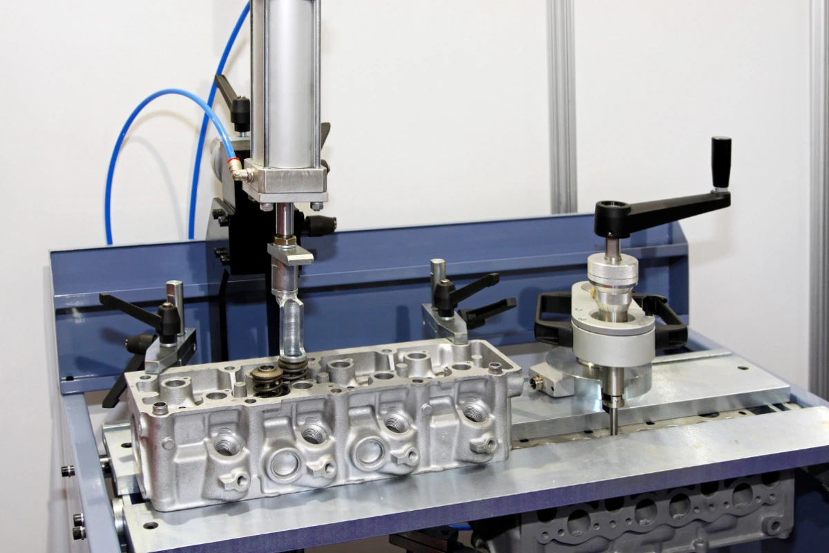
Die cast tooling is the production die in the die casting process. It forms the part and manages metal distribution, cooling, and ejection. The cavity alone does not address every production issue. Part geometry, alloy choice, visible surfaces, machining needs, and planned output all influence the tool concept.
Changing a part model before tool manufacture is usually easier than reworking a finished die. The practical goal is to agree on how the casting will fill, solidify, release, trim, and locate for any later operation. This review is a design decision, not a first-article approval or a production quality plan.
Which Part Details Shape the Die Design
The product drawing drives the tool design. The tooling team needs to see which surfaces control fit or appearance, which walls carry load, and which features remain as-cast or need later machining.
Parting Direction and Visible Surfaces
The parting direction determines how the die halves open and where the parting line appears on the casting. The parting line can leave a mark or flash that needs trimming, so the tooling review needs an explicit pull direction and a map of surfaces where that result would create a functional or appearance problem.
- Identify cosmetic faces and any trim area that the finished product can tolerate.
- Mark sealing lands and assembly interfaces where a parting line or gate remnant would affect function or appearance.
- Document any draft exception. Draft helps the casting release from surfaces parallel to the die-opening direction, but the tooling team sets the exception for the exact geometry and alloy.
Wall Transitions, Ribs, and Bosses
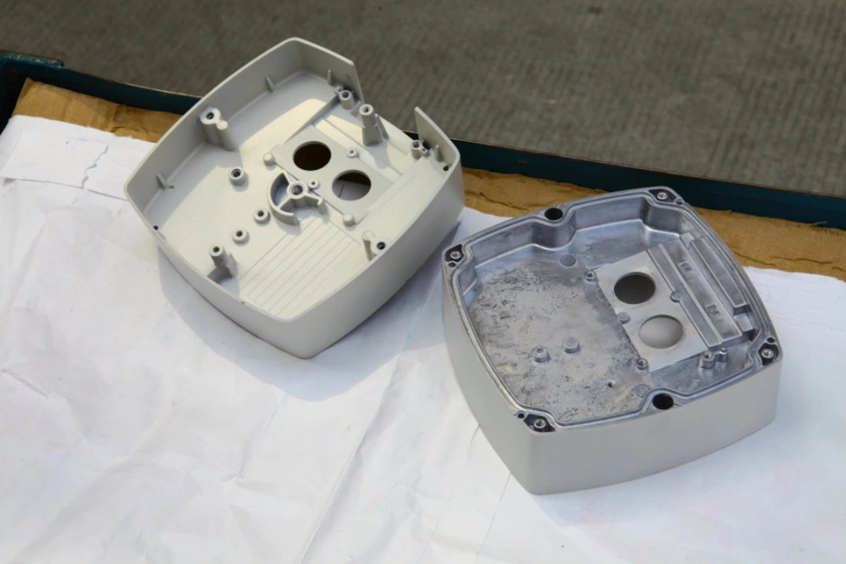
Wall sections and their transitions affect how a die fills and solidifies. More consistent wall thickness and smooth transitions give the die designer a clearer path for controlling local thermal conditions, while abrupt heavy sections can raise casting shrinkage risk and complicate that work. Ribs and bosses should support the part’s function without creating unnecessary local mass or trapped geometry, so the tooling team needs the functional reason for each thick area before deciding whether to form it in the cavity.
Side Features and Internal Geometry
Features that do not follow the die-opening direction often change the tool architecture. Side holes, undercuts, and internal forms may need a moving slide, a core, a change to the product geometry, or a secondary operation after casting. The tooling team should make this choice feature by feature, based on the feature’s function, location, finish requirement, and expected production program.
How Do Filling and Cooling Decisions Shape the Die?
A die directs molten metal through the cavity and manages heat as the casting solidifies. Gate, runner, overflow, vent, and cooling decisions therefore belong in one tooling review rather than separate conversations.
Gates, Runners, Overflows, and Vents
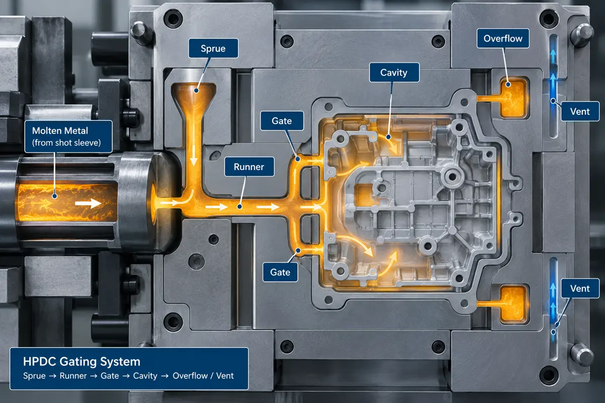
Gates and runners direct molten alloy into the cavity. Overflows and vents provide routes for metal and air at the end of the fill path. The tooling team needs to review their locations against thin areas, complex geometry, cosmetic faces, and regions where the part needs reliable material properties.
Gate placement also affects where trimming removes the casting from the runner system. Keep gate remnants and trim areas away from critical assembly faces when the product design permits it. If a gate location could affect a visible or functional surface, the product designer and die-casting team need to settle that tradeoff before tooling begins.
Cooling Layout and Local Hot Areas
Cooling channels help the die control temperature across the cavity. The cooling layout takes into account the cavity shape, gates, runners, overflows, local thick sections, and the selected alloy. The design review should identify local hot areas and show whether part geometry, gate arrangement, or the cooling concept needs revision. A buyer does not need to prescribe the cooling circuit, but should understand which product features are driving the design risk.
How Do Ejection and Secondary Machining Change the Tool?
Ejection and post-casting machining need early design work before the team freezes the die layout. A die that can form the geometry still needs to release the casting without damaging a protected surface and support any later cutting operation.
Part Retention and Ejector Locations
The tooling team decides which die half will retain the casting after solidification and where ejector pins can push. Ejector locations need material behind them and should not interfere with cosmetic faces, sealing surfaces, or features that locate the part in an assembly.
Part geometry affects this decision. Insufficient draft or an undercut can make the casting resist release, while a thin unsupported wall can limit the locations where ejector pins can push. Reviewing the release path early helps the team avoid a die layout that conflicts with the part’s visible or functional surfaces.
Machining Datums and Stock Allowance
Some holes, threads, bearing bores, sealing faces, and reference surfaces are more practical to machine after casting. The casting versus machining decision should identify these features early. When the process includes secondary machining, the die design needs stable locating features, tool access, and enough material where the machining operation will remove metal.
The die-casting and machining teams should review which features will remain as-cast and which ones a machinist will finish later. This decision also affects the order of operations. A machining fixture may use cast locating pads or functional geometry, so the team can build those features into the die design before tool manufacture begins.
Which Tool Architecture Fits the Production Plan?
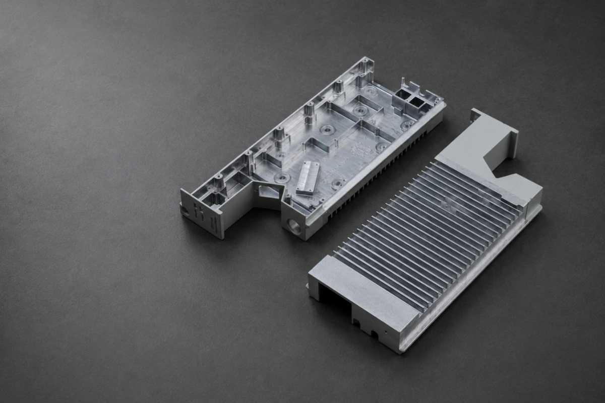
The tool architecture should match the part family and planned production program. A tool that suits one simple casting may not suit a family of related parts, multiple cavities, or complex side actions.
Cavity Count and Production Configuration
Cavity count changes the runner layout and tool configuration. In a multi-cavity die, matching flow paths and cavity conditions become part of the design task. The tooling review should record the intended cavity count and the expected production program that the configuration will support, then discuss the plan with a precision manufacturing partner that can assess tooling, casting, and later machining as one production route.
Slides, Cores, and Inserts
Slides and cores handle features outside the opening direction of a straight-pull die. Fixed inserts are also die components that the tooling team may use where the layout calls for them. These decisions can affect the parting line, ejection sequence, gate location, and later trim or machining operations.
Review these components as a system. A side feature that looks minor on a CAD model may change the tool layout, while a small product redesign may remove the need for a complex moving member. The design review should compare the practical options for the exact feature, not apply a generic rule to every undercut or hole.
Final Pre-Cut Tooling Review
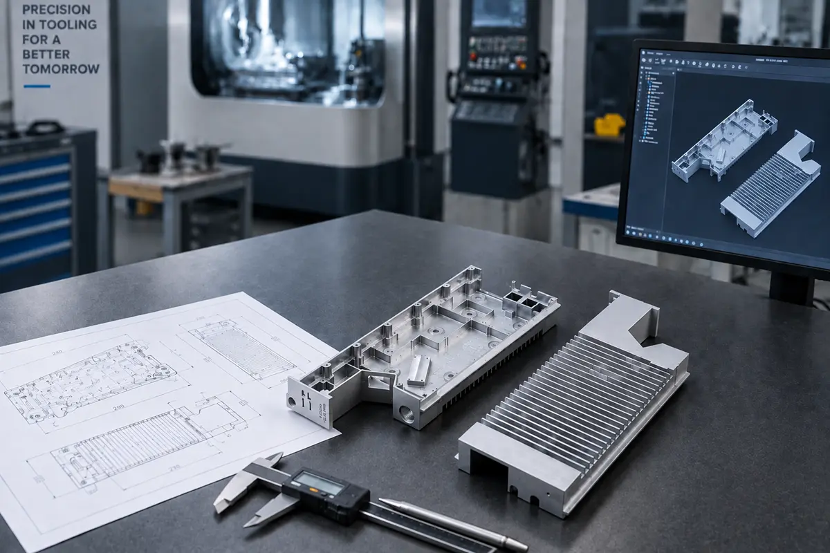
The final review should document the product decisions that the toolmaker will use to build the die. This record reduces ambiguity between the part drawing and the tooling design, but it does not replace the project’s later inspection, trial, or acceptance requirements.
| Tooling decision | Information to settle before die manufacture | What the decision changes |
|---|---|---|
| Parting strategy | Die-opening direction, protected surfaces, and allowable trim areas | Parting-line placement, flash location, and trim approach |
| Wall and rib layout | Functional wall sections, transitions, and reinforced areas | Cavity form and local thermal review |
| Side features | Undercuts, side holes, internal forms, and as-cast versus machined intent | Need for slides, cores, geometry changes, or secondary operations |
| Fill path | Alloy, fill-sensitive zones, visible faces, and critical functional areas | Gate, runner, overflow, and vent concept |
| Thermal control | Local thick sections and geometry that may need special attention | Cooling layout and review of local hot areas |
| Ejection | Retention direction, protected faces, and supported ejection areas | Ejector locations and release sequence |
| Post-casting machining | Features to machine, datum plan, fixture access, and material-removal zones | Locator features, access, and casting stock at machined areas |
| Production configuration | Intended cavity count and whether related parts share a tool | Die architecture and process-balance review |
The buyer should provide the latest CAD model, drawing revisions, alloy requirement, surface expectations, and the purpose of each critical feature. The tooling partner should return a design review that makes the proposed parting, gating, cooling, ejection, and machining assumptions visible before manufacturing starts.
What to Look for in a Tooling Partner
Look for a tooling partner that can connect the part definition to the full manufacturing route. Ask who will perform the tool design, which aluminum or zinc alloy the project will use, how the process will trim the casting, and whether the supplier can support the planned post-machining.
For parts that need both casting and secondary machining, Rollyu Precision lists mold design and tooling, aluminum and zinc die casting, and CNC post-machining for milling, drilling, reaming, and tapping on its Die-Casting Parts page. Before release, buyers can clarify the project-specific tooling configuration, machining scope, inspection requirements, and responsibility boundaries.
Frequently Asked Questions
Does Tool Steel Grade Alone Determine Die Performance?
No. Die performance also depends on the casting design, alloy, heat treatment, die geometry, process conditions, and maintenance. Tool steel selection still matters, but it does not correct a part design or thermal layout that does not suit the casting process.
How Does Expected Output Affect Cavity Count?
Expected output is one input to the cavity-count discussion for a die casting die. Part size, family-part requirements, slide needs, and cast-in inserts can also affect the tool type. The tooling team uses the CAD model and planned production program together when selecting the configuration.
Can Rollyu Support Both Die Tooling and Post-Machining?
Rollyu Precision lists mold design and tooling, die casting of aluminum and zinc alloys, and CNC post-machining on its Die-Casting Parts page. That page shows the available service scope, while the exact tool design, secondary features, and inspection needs remain project-specific.
