
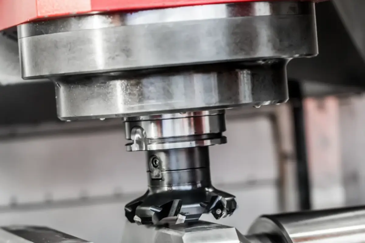

Climb milling is usually the starting choice on a rigid CNC machine with controlled backlash and secure workholding. Conventional milling still has a place when the feed system has backlash, the setup lacks stiffness, or the cutting edge needs to enter the material gradually.
The climb milling vs conventional milling choice affects chip formation, cutting force, heat, surface finish, and tool loading. This guide explains those effects and shows what engineers and buyers should review before approving a milling plan for a custom CNC part.
What Is the Difference Between Climb and Conventional Milling?
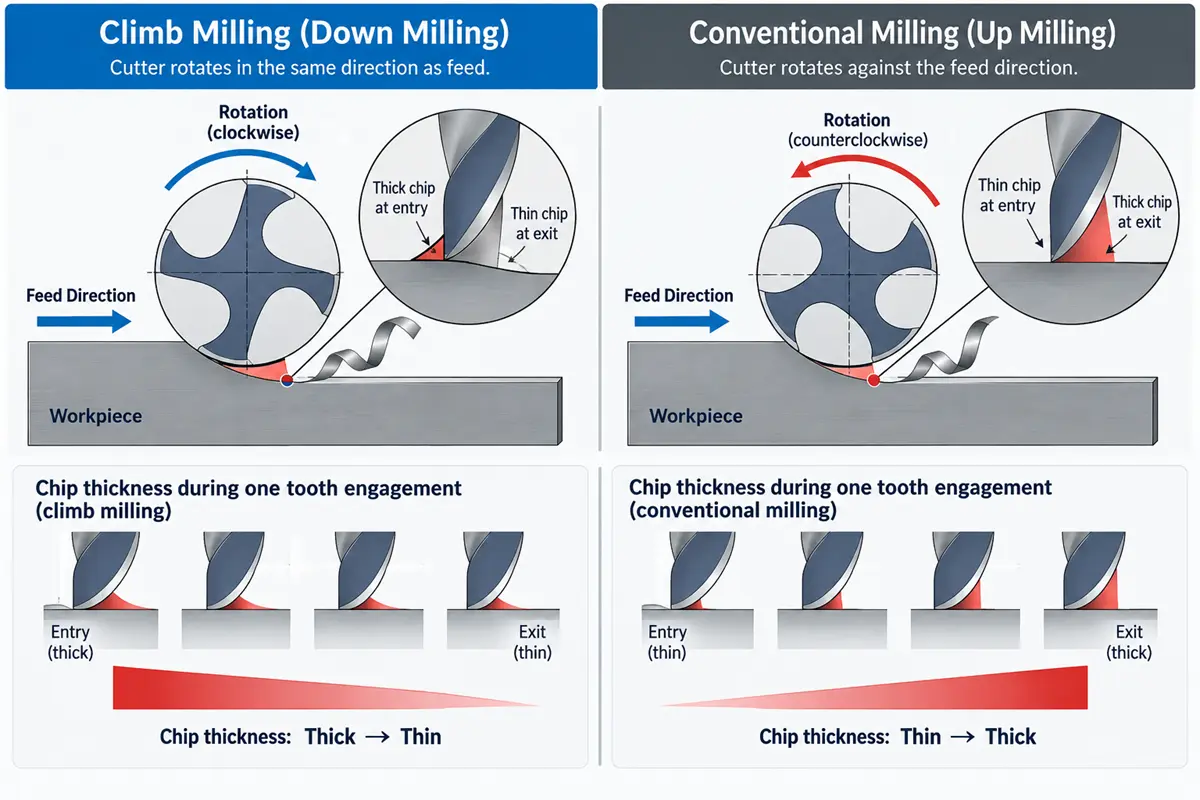
In CNC milling, the difference is the cutter’s rotation relative to feed at the point of contact. That relationship reverses how each tooth enters the material and how chip thickness changes through the cut.
| Comparison point | Climb milling | Conventional milling |
|---|---|---|
| Other common name | Down milling | Up milling |
| Cutter direction at contact | Moves with the feed | Moves against the feed |
| Chip thickness | Starts thick and ends thin | Starts thin and ends thick |
| Tooth entry | Engages the material at a higher chip thickness | Enters gradually from near-zero chip thickness |
| Chip flow | Tends to carry chips behind the cutter | Tends to place chips ahead of the cutter |
| Typical machine condition | Rigid CNC with controlled backlash | Backlash-sensitive or less stable feed system |
| Common use | General CNC cutting and finish passes when the setup is stable | Selected rough-surface, fragile-tool, thin-wall, or unstable-machine conditions |
| Main caution | Entry load and force direction can expose weak workholding or backlash | Entry rubbing and chip recutting can add heat and hurt the finish |
Climb Milling Chip Formation
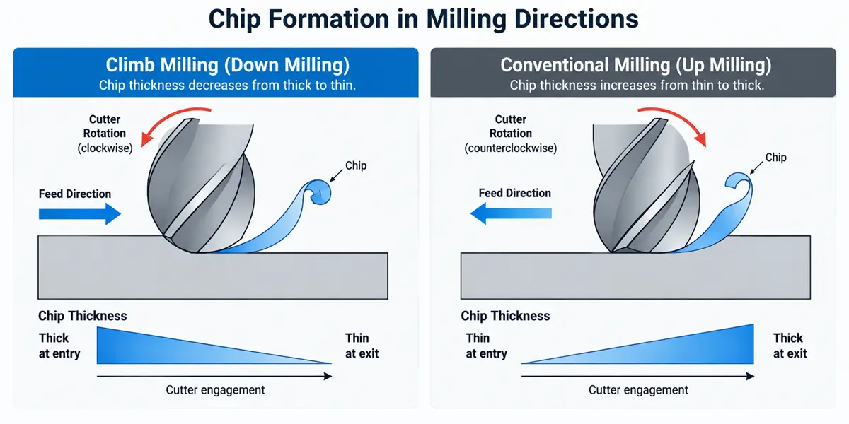
In climb milling, the cutter rotates in the same direction as the feed at the cutting zone. Each tooth starts at maximum chip thickness, then the chip tapers toward zero as the tooth exits.
This thick-to-thin path helps the edge begin cutting instead of sliding across the surface before it develops enough chip load. Chips also tend to move behind the cutter, which reduces the chance that another tooth will cut the same chip again.
Conventional Milling Chip Formation
In conventional milling, the cutter rotates against the feed at the cutting zone. The tooth starts at nearly zero chip thickness, then removes a thicker chip as it travels through the material.
The gradual entry can reduce the first impact on a brittle cutting edge. The same entry can make the edge rub before it cuts, especially when the programmed chip load is light. Chips also tend to collect ahead of the cutter, where recutting can mark the part and load the cutting edge.
How Does Milling Direction Affect CNC Part Quality?
Milling direction changes part quality through chip control, force direction, and tooth loading. The result still depends on cutter geometry, tool condition, radial engagement, feeds and speeds, machine stiffness, workholding, coolant or air delivery, and the shape of the feature.
Surface Finish and Chip Recutting
Climb milling often produces a cleaner finish on a stable setup because the edge begins with a defined chip and carries chips away behind the cut. Less entry rubbing and less chip recutting can reduce smearing, scratches, and secondary marks on a finished wall. A loose fixture, long tool overhang, worn edge, unstable engagement, or poor chip evacuation can still leave chatter or taper. A finish requirement therefore needs a measured acceptance value or an approved visual standard within the CNC machining quality control plan, not a process label alone.
Cutting Forces and Workholding
Climb milling and conventional milling load the machine, tool, and workpiece in different directions. The programmer needs to check two related conditions:
- Drive and fixture response: A climb cut can pull a feed system with backlash into the cut. The fixture must also resist the force without letting the part shift.
- Feature stiffness: Thin floors, slender walls, small tabs, and long-reach tools can deflect as the cutter removes material. Either direction can move a weak feature enough to change the measured size after the tool passes.
Heat, Rubbing, and Tool Wear
Conventional milling begins with a thin chip, so the cutting edge may rub before it shears the material. Seco Tools notes that this entry behavior adds friction and heat when the chip is too thin. Climb milling starts with more chip thickness and transfers more of the cutting heat into the chip under suitable conditions. Direction alone does not determine tool life. Excessive entry load can damage an edge, while insufficient chip thickness can accelerate rubbing and wear. The cutter manufacturer’s data for material, insert grade, engagement, and feed per tooth should control the final cutting parameters.
When Should a CNC Shop Use Climb Milling?
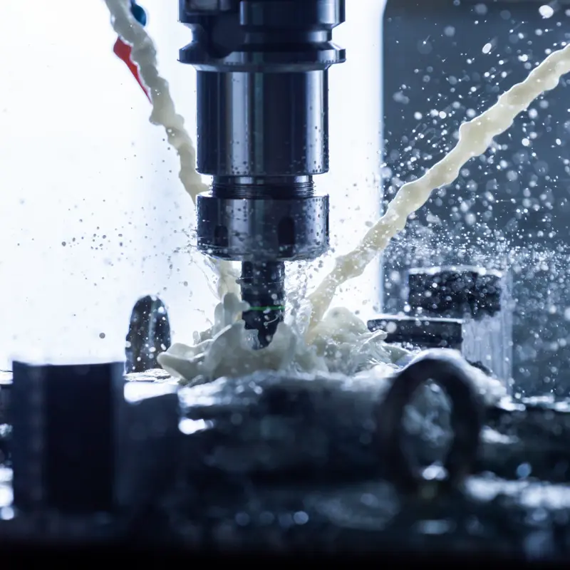
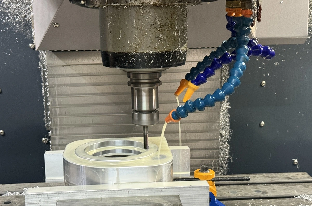
Climb milling is the usual starting point for CNC operations on a rigid machine with low or controlled backlash. Haas training material describes climb cutting as the direction normally desired on CNC equipment, and Seco Tools generally recommends down milling because it reduces entry rubbing and moves chips behind the cutter.
The method is a strong candidate for finish passes on external profiles, pocket walls, and other surfaces where chip recutting could leave visible marks. The setup still needs firm workholding, a stable tool, and a programmed entry that avoids a sudden load spike. For pockets and changing contours, the programmer should inspect actual cutter engagement in the CAM simulation instead of judging the complete path from one arrow.
When Is Conventional Milling the Better Choice?
Conventional milling is useful when the conditions make a gradual tooth entry more important than the usual advantages of climb milling. A feed system with meaningful backlash is the clearest case because the opposing force is more tolerant of play in the drive than a cutter that pulls the axis forward. A first article inspection review can compare the programmed direction with the measured result when the buyer and supplier include that evidence in the agreed approval scope.
Seco Tools also identifies rough-surfaced stock, brittle or hard cutting tools, thin-wall conditions, and heavy cuts on less stable machines as possible conventional-milling cases. These are starting points for process review, not universal rules. A hard outer layer, interrupted entry, weak wall, or delicate edge can respond differently as cutter position and support change. The shop should follow the toolmaker’s application guidance and confirm the choice during setup or first-article inspection.
How Should Buyers Review the Milling Plan for CNC Parts?
Buyers should define the required part result and give the CNC supplier enough context to choose a stable toolpath. A blanket note that says “climb mill” or “conventional mill” cannot replace dimensions, tolerances, finish requirements, and inspection criteria.
Part and Setup Conditions
Share the conditions that define the cut:
- Material grade, heat-treatment condition, stock form, and any preexisting scale or hard surface
- Thin walls, deep features, interrupted cuts, cosmetic faces, and areas with limited tool access
- Part quantity and any feature that needs a dedicated finish or inspection result
These details help the supplier choose cutter engagement, tool reach, workholding, and milling direction as one connected plan.
Rollyu Precision supports CNC machining parts across 3-axis, 4-axis, and 5-axis equipment, along with DFM review for manufacturability, tolerance, and feature risk. A quote review can flag features whose stiffness, access, or surface requirement may change the machining sequence. Project-specific tooling and cutting parameters remain subject to the drawing, material, and machine setup.
Drawing and Inspection Requirements
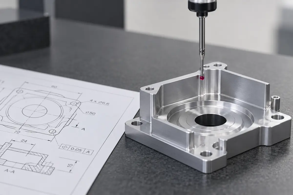
Put the required outcome on the drawing or purchase specification. Useful inputs include critical dimensions and tolerances, datum relationships, surface roughness where it affects function, cosmetic zones, burr limits, and the requested inspection record. If a particular milling direction is functionally required, identify the affected surface and explain the acceptance need so the supplier can review feasibility.
Rollyu Precision includes in-process and final dimensional inspection in its CNC machining workflow, with CMM and surface-finish inspection available for applicable features. Buyers can ask for the inspection scope to match the critical characteristics instead of assuming that a preferred cutter direction proves conformance.
Frequently Asked Questions
Can One CNC Part Use Both Climb and Conventional Milling?
Yes. A CNC program can use different directions for separate features or passes when the setup, cutter entry, surface condition, or wall support changes. The programmer may also change direction after roughing if the finish pass needs a different force path. Each choice should serve that feature instead of following a page-wide rule.
Is Full-Slot Milling Climb or Conventional Milling?
Full-slot milling engages both sides of the cutter, so one side of the slot is cutting in the climb relationship while the opposite side is cutting conventionally. Calling the whole slot one method hides this geometry. Chip evacuation, tool deflection, radial engagement, and the entry method usually matter more than assigning a single direction label.
Does the Workpiece Material Decide the Milling Direction?
No. Aluminum, plastic, steel, or titanium may change cutter geometry, speed, feed, coolant, and tool grade, but the material name alone does not decide between climb and conventional milling. Machine backlash, feature stiffness, stock surface, tool material, cutter position, and finish requirements also affect the choice. The shop should use the cutter supplier’s material-specific data and confirm the direction against the actual setup.
