

What Is Quality Testing for CNC Machined Parts?
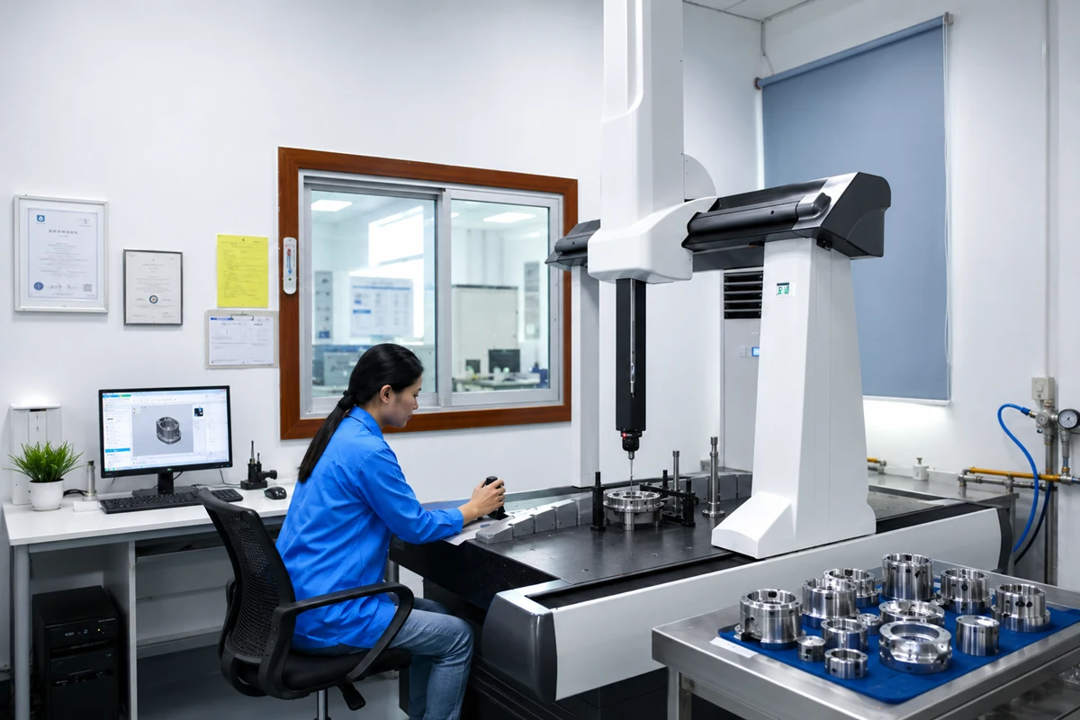
Quality testing for CNC machined parts is the planned verification of material, dimensions, GD&T, threads, surface condition, functional interfaces and documentation from incoming inspection through final release. A defensible process combines first article inspection, in-process quality control, dimensional inspection, CMM or optical measurement where appropriate, final inspection and traceable quality records—not a single end-of-line check.
For mechanical engineers or technical buyers, the practical question is not only whether a supplier owns inspection equipment. It is whether the supplier can convert the drawing into an inspection plan, select a capable measurement method, detect process drift early, contain nonconformance and provide objective evidence that the released parts meet requirements.
When you order a precision CNC machined component, receiving a part that looks correct is not enough.
A component can appear visually acceptable and still fail because of:
- an incorrect material grade;
- an out-of-tolerance bore;
- an incorrect datum relationship;
- excessive flatness or position error;
- thread problems;
- an unacceptable sealing surface;
- dimensional drift during production;
- surface damage after finishing;
- incomplete inspection documentation; or
- loss of material and batch traceability.
For medical devices, semiconductor equipment, photonics systems, robotics, motion-control assemblies, vacuum hardware and space-related equipment, these issues can become expensive after the part reaches assembly.
That is why CNC machining quality control should not begin at final inspection.
At Rollyu Precision, quality inspection starts with the drawing and material requirements, continues through first-piece and in-process verification, and ends with final inspection, documentation, traceability and controlled release.
Rollyu Precision operates under ISO 9001 and ISO 13485 quality management systems and combines dimensional inspection, CMM measurement, optical inspection, surface verification, material identification and documented inspection records to support precision manufacturing programs.
What Is CNC Machining Quality Control?
CNC machining quality control is the documented process used to verify that machined components conform to the customer’s released drawing, CAD model, specifications and functional requirements.
A capable inspection process evaluates more than dimensional size.
Depending on the component, inspection may include:
| Quality Requirement | Typical Verification |
| Material grade | Material certificate, PMI when required |
| Linear dimensions | Caliper, micrometer, height gauge, CMM |
| Bore dimensions | Bore gauge, pin/plug gauge, CMM |
| GD&T | CMM, vision system, indicator or qualified fixture |
| Hole position | CMM or vision measurement |
| Threads | Correct GO/NO-GO thread gauges |
| Surface roughness | Surface roughness tester / profilometer |
| Cosmetic condition | Controlled visual inspection |
| Hardness | Hardness testing when specified |
| Surface treatment | Visual, dimensional and certificate verification |
| Critical interfaces | Application-specific dimensional or functional verification |
| Traceability | Material lot, work order, inspection and measurement records |
The most important principle is simple:
Inspection requirements come from the customer drawing, purchase order, approved specification and applicable control plan—not from an inspector’s personal judgment.
Quality Inspection Services for CNC Machined Parts: What Mechanical Engineers and Technical Buyers Need to Verify
When engineers search for quality inspection services or precision inspection services, they are usually evaluating whether a machining supplier can reduce receiving-inspection burden and production risk. The inspection plan should connect the drawing to measurable evidence at each production stage.
| Buyer Concern | Inspection Evidence | Typical Search Intent |
| Is the correct material being used? | Material certificate, heat/lot traceability, PMI or hardness when specified | material verification; material certification; material traceability |
| Will the part assemble correctly? | Dimensional inspection, critical dimension inspection, thread and hole verification | dimensional inspection services; tight tolerance inspection |
| Are datum relationships and geometry correct? | CMM / vision / qualified fixture; GD&T verification | CMM inspection services; GD&T inspection |
| Will sealing, sliding or optical surfaces perform? | Surface texture, flatness, visual/cosmetic and functional-surface checks | surface finish inspection; flatness inspection |
| Is production stable? | First article approval, in-process inspection, SPC/trend data where appropriate | first article inspection; in process quality control |
| Can the supplier prove conformance? | CMM reports, dimensional reports, FAIR/FAI data, material certificates, traceability | inspection reports; first article inspection report |
Rollyu Precision’s 8-Step CNC Machining Inspection Process
A strong CNC machining inspection process should identify risk before production, detect process drift while parts are being manufactured, and provide objective evidence before shipment.
Our quality-control workflow can be summarized as:
Drawing Review → Material Verification → First-Piece Inspection → In-Process Inspection → Dimensional & GD&T Verification → Surface & Thread Inspection → Final Inspection → Documentation & Release
Drawing, CAD and Quality Requirement Review
Quality control begins before machining.
Before production, the engineering and quality teams review the latest applicable customer requirements.
The review may include:
Part identification and revision
The part number, drawing revision, CAD model revision and work-order information must correspond to the correct production lot.
Material requirements
We review alloy or polymer grade, temper or condition, heat-treatment requirements and material-certification requirements.
Dimensional tolerances
Critical diameters, thicknesses, hole dimensions, fits, depths and other controlled dimensions are identified.
GD&T requirements
Datums, position, flatness, perpendicularity, parallelism, runout, profile and other geometric controls are reviewed according to the drawing.
Functional surfaces
Special attention may be assigned to sealing surfaces, sliding surfaces, optical mounting datums, vacuum interfaces or other customer-designated CTQ features.
Threads
Thread system, size, pitch/TPI, class, depth and gaging requirements are confirmed.
Surface requirements
Surface roughness, anodizing, passivation, electropolishing, plating, polishing, coating and cosmetic requirements are reviewed.
Inspection documentation
If the customer requires actual dimensional data, a CMM report, balloon drawing, FAI report, material certification, surface-roughness data or other documentation, this should be defined before production.
Why this matters to mechanical engineers and technical buyers
The earlier an ambiguous drawing requirement is identified, the lower the risk of producing an entire batch to an incorrect interpretation.
For high-value precision components, a drawing review is therefore not paperwork—it is the first quality-control operation.
Incoming Material Verification and Traceability
A precision part cannot be better than the material from which it is manufactured.
Before machining, incoming material can be checked for:
- material grade and specification;
- condition or temper;
- heat or lot number;
- material certificate identity;
- stock dimensions and machining allowance;
- visible damage, corrosion or defects;
- hardness where specified; and
- chemical composition verification when PMI is required.
For projects requiring additional assurance, Positive Material Identification (PMI) can help verify alloy composition and reduce the risk of material mix-up.
This is especially important when similar-looking materials have very different properties.
Examples include:
303 vs. 304 stainless steel,
304 vs. 316L stainless steel,
6061 vs. 7075 aluminum,
different precipitation-hardening stainless steels,
and titanium or specialty alloys.
Material traceability can link the finished component back to its material heat or lot, supplier documentation and production records.
Incoming Inspection vs Receiving Inspection: Why Material Control Starts Before Machining
Incoming inspection and receiving inspection are commonly used buyer-search terms for the same quality gate: verifying purchased material or components before they consume machining capacity. The exact scope depends on the PO and control plan, but the purpose is to confirm identity, condition, traceability and suitability before production starts.
When hardness is specified, a Rockwell hardness test or another required hardness method may be used depending on the material and governing specification. Chemical composition verification may use a material elemental analyser / PMI method when required. These checks supplement—not replace—the material certificate and drawing requirements.
First-Piece Inspection Before Production Release
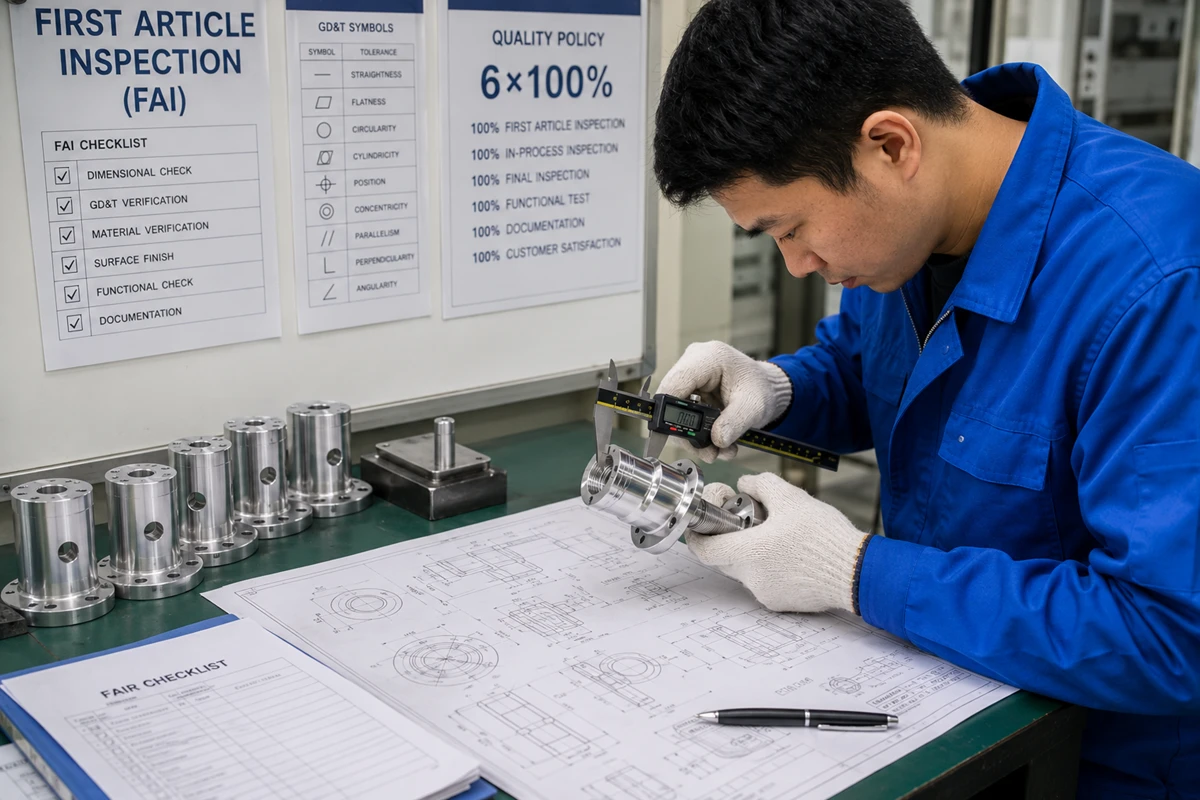
One of the most important quality gates in precision machining is the first-piece inspection, sometimes called first-off or setup approval inspection.
The purpose is not simply to measure the first finished component.
It is to verify that the manufacturing system has been correctly established.
This may include verification of:
- CNC program and revision;
- machine setup;
- fixture location;
- datum strategy;
- cutting tools;
- tool offsets;
- material;
- machining sequence;
- dimensional characteristics;
- GD&T characteristics;
- surface condition;
- thread condition; and
- inspection method.
Production should not continue uncontrolled if the first-piece result indicates that the process is not producing a conforming component.
Typical first-piece triggers
A new setup, new program, significant fixture change, engineering revision, relevant tool or offset change, machine event, material change or other defined control-plan trigger may require re-verification.
The exact requirement depends on the part risk and control plan rather than a universal shop-floor rule.
First Article Inspection Report (FAIR): What Should Mechanical Engineers and Technical Buyers Define?
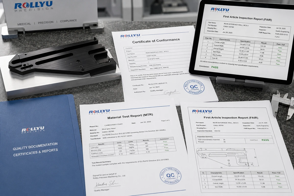
A First Article Inspection Report is the documented evidence generated from the initial production or other defined validation event. The scope should be agreed before production because “FAI” can mean different levels of reporting—from selected critical dimensions to a ballooned drawing with feature-by-feature results.
- Part number, drawing/model revision and production lot identity.
- Ballooned characteristic numbers when a full layout is required.
- Nominal requirement, tolerance, actual measured result and acceptance status.
- Inspection method or equipment identification when required.
- Material and special-process certificates linked to the part or lot.
- CMM report or supporting measurement evidence for complex GD&T features.
• Authorized review and release status.
In-Process Quality Control During CNC Machining
Final inspection alone cannot prevent a machining process from producing defective parts for several hours.
That is why In-Process Quality Control (IPQC) is important.
During production, selected characteristics can be monitored to detect changes caused by:
- tool wear;
- tool breakage;
- thermal variation;
- workholding movement;
- fixture contamination;
- material variation;
- offset drift;
- thin-wall deformation;
- machine condition; or
- process changes.
Inspection frequency and sample quantity should be based on process risk, tolerance, stability, capability, production volume and customer requirements.
For example, a stable noncritical dimension may not require the same inspection strategy as a CTQ sealing diameter or tight-tolerance hole position.
What happens if an in-process result is out of specification?
A controlled response should include:
Stop or hold → Confirm the measurement → Contain affected parts → Identify the last known-good point → Correct the process → Reinspect → Resume production only after verification
This approach helps prevent one machining problem from becoming a batch problem.
Dimensional Inspection, CMM Inspection and GD&T Verification
After the machining process is established, dimensional inspection verifies the drawing characteristics using the most capable method for each feature. This can include calipers, micrometers, bore gauges, height gauges, pin/plug gauges, CMM inspection, optical measurement and dedicated fixtures. Critical Dimension Inspection focuses extra control on CTQ features that directly affect fit, sealing, motion, alignment or assembly yield.
Surface Finish, Thread, Hole and Cosmetic Inspection
The component is also checked for surface roughness where specified, thread function, hole size/depth, burrs, machining marks, scratches and dents, and the condition of functional surfaces. Visual acceptance criteria should be tied to customer requirements rather than subjective “looks good” judgment.
Final Quality Control (FQC / OQC) Before Shipment
Final inspection confirms that all required operations are complete and that the release package is ready. Depending on risk and the control plan, this can include final dimensional verification, cosmetic inspection, marking, cleaning, packaging checks and review of required certificates and inspection reports.
Quality Documentation, Traceability and Controlled Release
The final quality gate links the physical parts to their objective evidence: drawing revision, material lot, production work order, inspection equipment, measured data, nonconformance disposition if any, inspector/approver and shipment release. This traceability is especially valuable when a customer must qualify a supplier or investigate a later assembly issue.
Dimensional Inspection for Precision Machined Parts
Dimensional inspection verifies that physical component dimensions correspond to the released engineering requirements.
Different features require different measurement strategies.
Caliper Inspection
Digital calipers are useful for suitable general dimensions such as:
- overall length;
- external dimensions;
- step dimensions;
- certain internal dimensions; and
- depth measurements.
However, display resolution alone does not determine whether a caliper is capable of verifying a tight tolerance.
Measurement-tool selection should consider the actual tolerance, equipment capability, calibration status, contact geometry and repeatability.
Micrometer Inspection
Micrometers provide greater control over precision external dimensions and can be used for:
- diameters;
- thickness;
- shoulders;
- precision turned features; and
- thin precision components where the measuring method is appropriate.
Controlled measuring force and consistent contact location help improve repeatability.
For cylindrical parts, measurements at multiple locations may also help identify taper or ovality where relevant.
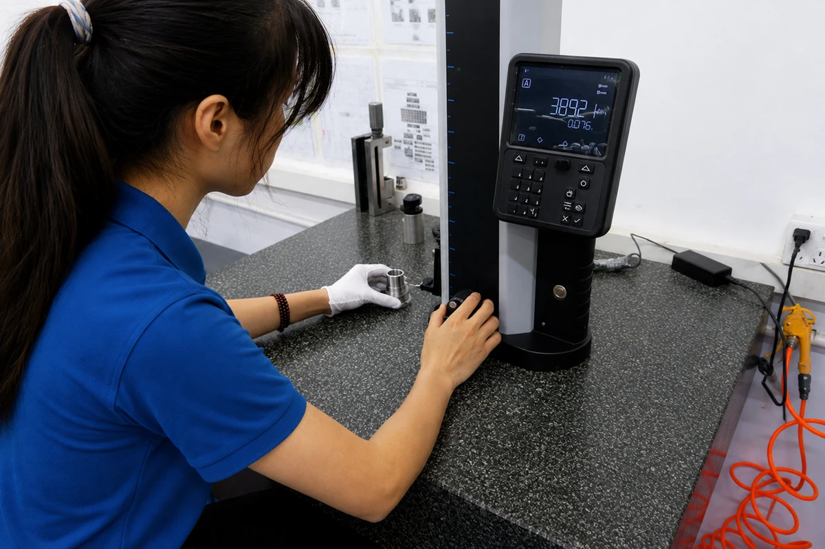
Height Measurement
Digital height gauges used on controlled reference surfaces can support measurement of:
- component height;
- step differences;
- center locations;
- feature relationships; and
- comparative dimensional characteristics.
Cleanliness of the surface plate, instrument base and component reference surface is critical because contamination can alter the measurement datum.
How Is Flatness Measured on CNC Machined Parts?
Flatness can be measured by several methods depending on part size, tolerance and the required uncertainty. Common approaches include a surface plate with an indicator for comparative flatness, a CMM for coordinate-based flatness evaluation, or specialized metrology equipment for demanding surfaces. The part must be supported and inspected in the state defined by the drawing or procedure, because clamping can mask free-state distortion.
Full Dimensional Inspection vs Critical Dimension Inspection
Full dimensional inspection (sometimes called full layout inspection) records every drawing characteristic within the agreed scope. Critical dimension inspection focuses on CTQ or key features that have the greatest effect on function, assembly or risk. New products and first articles may justify a full layout, while stable repeat production often uses a risk-based control plan with enhanced monitoring of critical features.
Caliper vs Micrometer: Which Is Better for CNC Inspection?
Neither tool is universally “better.” A caliper is efficient for suitable general dimensions, while a micrometer offers controlled contact and higher capability for many precision external measurements. The correct choice depends on tolerance, geometry, calibration status, repeatability and measurement uncertainty—not only the number of digits shown on the display.
CMM Inspection and GD&T Verification
For complex precision parts, measuring only length, width and diameter does not provide enough information.
The relationship between features can be just as important as their individual sizes.
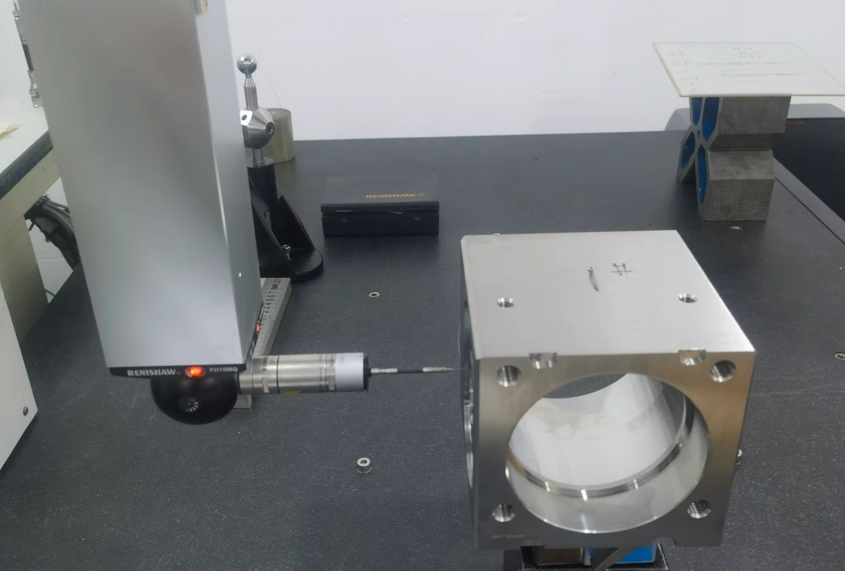
A Coordinate Measuring Machine (CMM) can be used to verify complex three-dimensional geometry and datum-related characteristics.
Typical CMM applications include:
| Feature | Typical CMM Verification |
| Hole patterns | Position |
| Precision baseplates | Flatness / parallelism |
| Machined housings | Perpendicularity / position |
| Complex 5-axis parts | Surface or line profile |
| Bores | Diameter and datum relationship |
| Multiple machined faces | Datum-based feature relationships |
| Shafts and rotating components | Runout / coaxial relationships when specified |
| Optical mounting components | Datum and mounting-feature geometry |
A valid CMM inspection requires more than placing a part on the machine.
The measurement strategy must establish the correct drawing datums, use qualified probes and apply the correct alignment and measurement program.
For repeat production, maintaining inspection-program revision and datum strategy improves measurement consistency and traceability.
CMM Inspection Services: What Should Be Included?
For supplier evaluation, “we have a CMM” is not enough. A useful CMM inspection service defines the datum alignment, feature strategy, program revision, probe qualification and report format needed to make the result repeatable and traceable.
| CMM Inspection Element | Why It Matters |
| Drawing datum alignment | Ensures position, profile and orientation are evaluated from the intended datum reference frame. |
| Probe qualification / setup | Reduces measurement error from incorrect stylus or calibration state. |
| Program and revision control | Makes repeat inspections comparable across lots and engineering changes. |
| Point density / scanning strategy | Supports appropriate evaluation of complex profiles, bores and surfaces. |
| CMM dimensional report | Provides actual measured evidence for customer review and receiving inspection. |
CMM vs Optical Inspection: which method should be used?
| Method | Best Fit | Limitations / Control Considerations |
| CMM inspection | 3D datum relationships, true position, profile, complex geometry, bores and multi-face features | Contact accessibility, fixturing, program strategy and measurement uncertainty must be controlled. |
| Optical / vision inspection | Small profiles, edges, angles, micro-features and non-contact measurement | Requires suitable contrast, focus, lighting, calibration and a feature that can be reliably imaged. |
| Manual metrology | Simple accessible dimensions, fast process checks | Operator technique and instrument capability become increasingly important as tolerance tightens. |
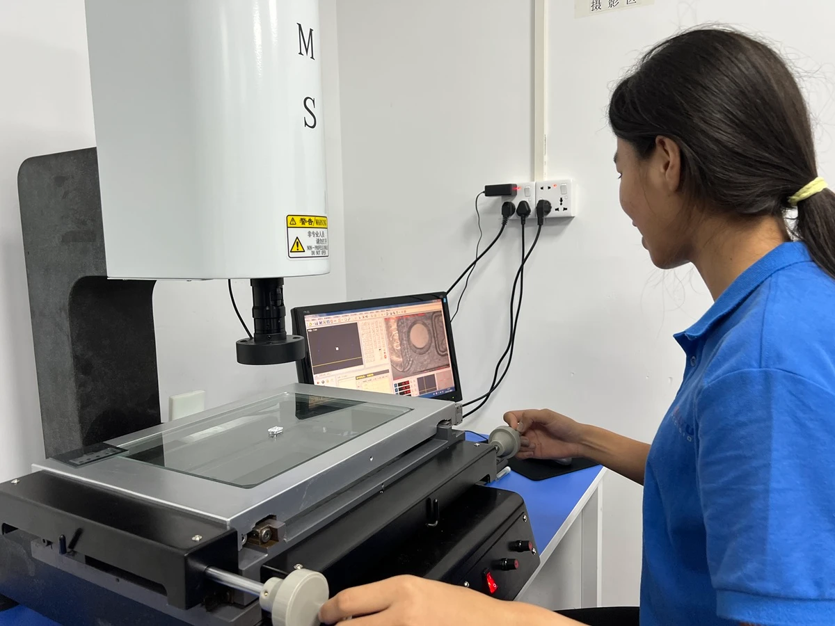
Optical Inspection for Small and Complex Features
Some machined features are better inspected without contacting the component.
Optical and vision systems can be useful for:
- small machined components;
- narrow slots;
- fine edges;
- profiles;
- angles;
- hole features;
- chamfers;
- small geometric details; and
- components where contact measurement would be difficult.
For miniature medical, photonics, sensor and precision-instrument components, optical measurement can complement conventional hand tools and CMM inspection.
Surface Roughness and Functional Surface Inspection
A surface that looks smooth is not necessarily Ra 1.6, Ra 0.8, or Ra 0.4. Surface roughness is a measurable engineering characteristic and must be verified with proper inspection equipment to confirm compliance with drawing requirements.
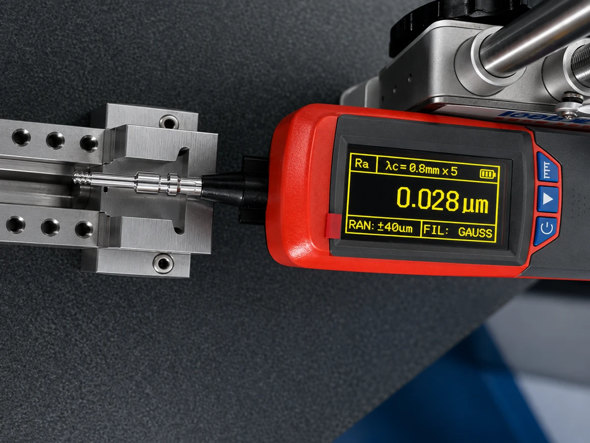
When a drawing specifies a numerical surface-texture requirement, an appropriate quantitative method should be used.
Important surfaces may include:
Sealing Surfaces
Inspection may consider:
- surface roughness;
- flatness;
- scratches;
- dents;
- machining marks;
- waviness;
- cleanliness; and
- sealing geometry.
For vacuum or fluid-control components, a dimensionally correct part can still fail if the sealing interface is damaged.
Optical and Precision Datum Surfaces
Optical and precision datum surfaces should be inspected for flatness, perpendicularity, location, surface finish, scratches, handling damage, and cleanliness to ensure dimensional accuracy and functional performance.
Inspection may consider:
- flatness;
- perpendicularity;
- location;
- surface finish;
- scratches;
- handling damage; and
Medical and Life-Science Components
Medical and life-science components may require verification of surface finish, burr control, cleanliness, special finishing, material traceability, and dimensional records to ensure quality and compliance.
Depending on customer requirements, inspection may also include:
- surface finish;
- burr control;
- cleanliness;
- passivation or electropolishing condition;
- material traceability; and
- dimensional records.
Machining Marks vs Scratch and Dent: Why the Difference Matters
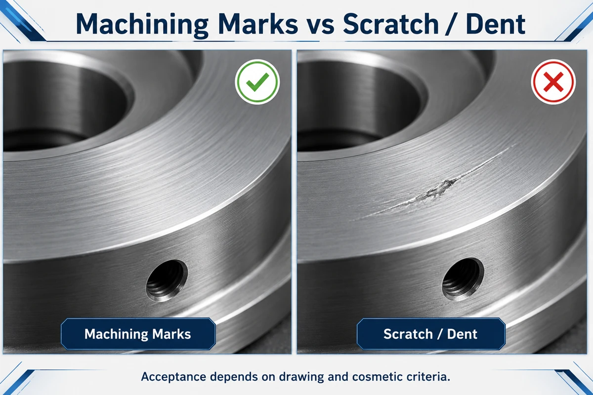
“Machining marks,” “scratch and dent,” chatter and handling damage describe different defect mechanisms. Uniform tool marks can be an expected result of the machining process if the specified surface texture and cosmetic requirements are met. A scratch, dent or gouge is usually localized damage from handling, chip drag, impact or unintended contact and may affect sealing, datum seating, appearance or fatigue performance. Acceptance must follow the drawing and customer cosmetic criteria.
Surface Finish Inspection vs Visual Inspection
Visual inspection can identify obvious scratches, burrs, dents, discoloration and machining defects, but it cannot assign a reliable numerical Ra or Rz value. When a numerical surface-finish requirement is specified, surface roughness testing / profilometer measurement should provide the quantitative evidence. Visual and tactile checks can complement—not replace—the required measurement method.
Thread and Hole Inspection
Thread quality is a common source of assembly problems because a thread can look acceptable while still being dimensionally unsuitable.
Rollyu uses the correct thread gaging method for the applicable thread system and customer requirement.
Inspection may include:
- GO/NO-GO functional gaging;
- thread size and class;
- thread depth;
- usable engagement;
- thread damage;
- burrs;
- minor diameter or pre-tap hole condition; and
- entry chamfer.
The key rule is that the correct calibrated gage must match the thread system, size, pitch and tolerance class.
A shop-floor rule for one thread standard should not automatically be applied to every metric, Unified, pipe or special thread.
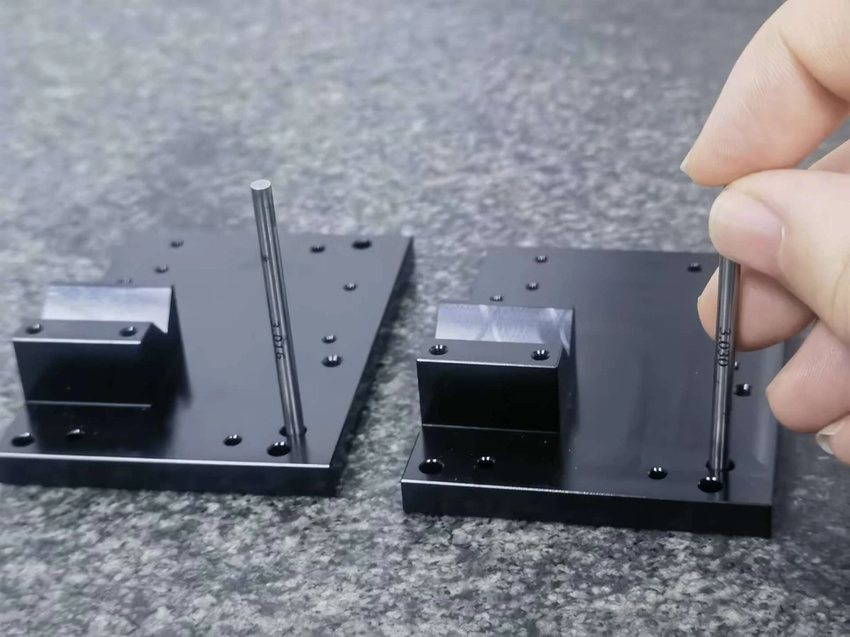
How to Measure Thread Size and Verify CNC Machined Threads
The search question “how to measure thread size” is often really a sourcing question: how does the supplier prove that an internal or external thread will assemble correctly? A complete thread inspection starts by identifying the thread system, nominal diameter, pitch or TPI, tolerance class and required engagement. Functional acceptance then uses the correct calibrated thread plug gauge or thread ring gauge under the governing standard, with additional dimensional or optical checks when the drawing requires them.
| Thread / Hole Check | Typical Tool | What It Verifies |
| Internal thread functional acceptance | GO / NO-GO thread plug gauge | Functional size / class according to the specified thread system and gaging rule. |
| External thread functional acceptance | GO / NO-GO thread ring gauge | Functional fit of the external thread. |
| Pitch / TPI identification | Thread pitch gauge | Confirms pitch family; not sufficient by itself for full thread acceptance. |
| Minor / pre-tap hole size | Pin / plug gauge, bore measurement | Confirms the hole condition supporting thread formation. |
| Thread depth / usable engagement | Depth gauge or defined functional method | Confirms usable threaded length and bottom condition. |
| Thread profile / damage | Optical comparator / vision / visual check where appropriate | Detects incomplete, damaged or abnormal thread form. |
Cosmetic and Visual Inspection
Precision-part quality is not limited to numerical dimensions.
Visual inspection can identify defects such as:
| Defect | Possible Quality Risk |
| Scratch / scoring | Cosmetic failure, sealing risk, datum damage |
| Dent / impact mark | Geometry or functional-surface damage |
| Burr / sharp edge | Assembly interference, injury, contamination |
| Chatter marks | Surface finish and dimensional stability |
| Corrosion / discoloration | Material or finishing problem |
| Overcut / gouge | Permanent geometry loss |
| Missing feature | Assembly or functional failure |
| Warpage / deformation | Flatness, profile or assembly failure |
Functional surfaces normally require tighter control than hidden nonfunctional surfaces.
For customer-visible cosmetic components, objective acceptance criteria are preferable to subjective statements such as “looks good.”
Where cosmetic requirements are important, the customer can define surface zones, defect size, quantity, viewing conditions or approved limit samples.
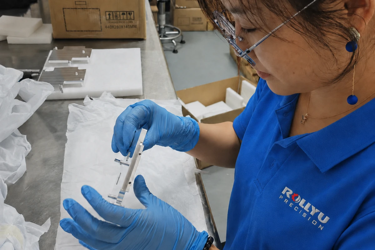
Cosmetic Acceptance Criteria: Turn Subjective Appearance Into Measurable Rules
For appearance-critical parts, define surface zones, lighting, viewing distance, magnification if any, defect type, maximum size/quantity and approved limit samples. This prevents disagreements caused by vague requirements such as “no visible scratches.” Functional sealing, optical, medical-contact and datum surfaces should always follow their functional requirements even if a general cosmetic rule would otherwise allow the defect.
Final Inspection Before Shipment
After all required machining and finishing operations are complete, finished components enter final quality verification.
Final inspection may confirm:
- required dimensions;
- CTQ characteristics;
- GD&T;
- threads;
- surface quality;
- cosmetic appearance;
- material traceability;
- required surface treatment;
- cleaning condition;
- marking;
- quantity;
- inspection documentation; and
- packaging requirements.
Final inspection is an important release gate, but it should not be expected to replace a controlled manufacturing process.
The best quality system detects variation during machining rather than waiting until every part is finished.
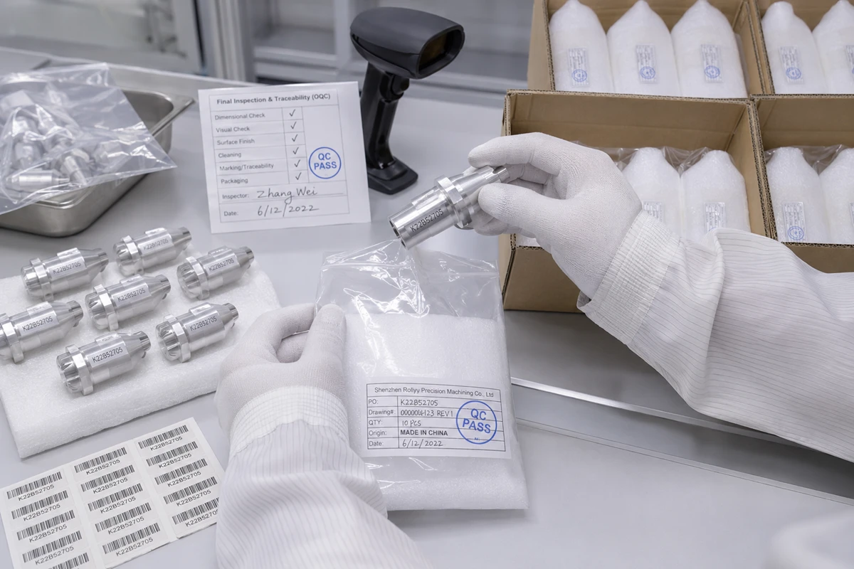
100% Inspection vs Sampling Inspection: Which Is Better?
Neither is automatically superior. 100% inspection is appropriate when the customer requires it or when a characteristic is safety-critical, highly critical, unstable or otherwise requires full verification. Sampling inspection can be appropriate for stable, lower-risk characteristics when permitted by the contract and supported by a capable process and control plan. Sampling never authorizes shipment of a known nonconforming lot.
| Decision Factor | 100% Inspection Tends to Fit | Sampling / Process Monitoring Tends to Fit |
| Feature risk | Safety, regulatory, sealing or highly critical CTQ | Lower-risk characteristics with demonstrated process stability |
| Process capability | New, unstable or not yet capable | Stable and capable process with defined control limits |
| Customer requirement | Explicit 100% requirement | Sampling explicitly permitted |
| Detection economics | Failure cost is much higher than inspection cost | Inspection itself is destructive, costly or unnecessary when process evidence is strong |
| Best practice | Combine with process control; do not rely only on final sorting | Use a documented sampling/control plan and react to any detected nonconformance |
Inspection Documentation and Traceability
For high-value precision manufacturing, a customer may need more than a box of parts.
They may also require objective quality evidence.
Depending on project requirements, documentation can include:
| Document / Record | Purpose |
| Material Certificate | Verify material source/grade information |
| First-Piece Inspection Record | Validate initial manufacturing setup |
| Balloon Drawing | Link drawing characteristics to inspection results |
| Dimensional Inspection Report | Record measured dimensions |
| CMM Report | Record complex dimensional and GD&T results |
| Surface Roughness Data | Verify specified surface texture |
| Hardness Result | Verify specified material/heat-treatment condition |
| Surface Treatment Certificate | Support special-process verification |
| NCR / Disposition Record | Document controlled nonconformance |
| Final Inspection Record | Provide shipment-release evidence |
Traceability can connect a component or production lot to information such as:
part number → drawing revision → material lot → production work order → machine/process → inspection equipment → measured data → inspector → final release
For medical, scientific, semiconductor, photonics and other high-value equipment programs, this evidence can be as important as the physical component itself.
What Inspection Reports Should a CNC Machining Supplier Provide?
The required documentation depends on the RFQ, drawing and industry. Mechanical engineers and technical buyers should define the package before order placement instead of assuming every supplier report contains the same information.
- Dimensional Inspection Report with nominal, tolerance and actual measured values for the agreed characteristics.
- CMM Report for complex GD&T or 3D dimensional inspection where required.
- First Article Inspection Report / FAIR and ballooned drawing when the initial-production approval scope requires it.
- Material Test Report / mill certificate and heat or lot traceability where required.
- Certificate of Conformance (CoC) when contractually required.
- Surface-finish, hardness, coating or special-process evidence when invoked by the drawing or PO.
- NCR / deviation / concession linkage for any authorized nonconformance affecting the shipment.
- Final inspection and release record linked to the shipped lot.
What Happens When a Part Fails Inspection?
A professional quality system should not hide or informally accept an out-of-specification result.
At Rollyu, the appropriate response follows a controlled nonconformance process.
Contain → Identify → Record → Evaluate → Disposition → Reverify → Close
Containment
Potentially affected components are placed on hold to prevent unintended processing or shipment.
Identification
The nonconforming status, part number, lot and affected quantity are identified.
Documentation
The actual result and specified requirement are recorded.
Instead of writing only:
“Dimension NG”
a useful quality record identifies the requirement, actual measurement, location and affected quantity.
Engineering and Quality Evaluation
The effect on fit, function, safety, assembly and downstream characteristics is evaluated.
Disposition
Depending on authorization and customer requirements, disposition may include:
- rework to the original requirement;
- approved repair;
- concession/use-as-is;
- scrap; or
- return to supplier.
An inspector should never silently widen a customer’s tolerance.
Why “Use-As-Is” Is Not the Same as Passing Inspection
If a measured feature is outside the drawing requirement, the product is nonconforming until an authorized disposition is completed. A concession or use-as-is decision must be documented and approved by the appropriate authority, including the customer when contractually required. This protects both the engineer , buyer and supplier from undocumented tolerance changes becoming an uncontrolled precedent.
Reinspection
After authorized rework, affected and related characteristics are reinspected before release.
This is especially important because rework on one feature may affect an adjacent dimension, datum, surface finish, flatness or wall thickness.
How We Select the Right Inspection Method
One common misunderstanding in precision machining is:
“Tight tolerance = use CMM.”
The correct approach is more detailed.
Inspection method selection considers:
- tolerance;
- feature geometry;
- datum relationship;
- part size;
- required measurement uncertainty;
- equipment capability;
- repeatability;
- measurement force;
- production quantity;
- accessibility;
- functional importance; and
- customer reporting requirements.
A micrometer may be the best choice for one precision diameter.
A CMM may be better for a position tolerance related to three datums.
A vision system may be better for a miniature profile.
A thread plug gauge may provide the correct functional verification for an internal thread.
A surface roughness tester may be necessary when an actual Ra value is required.
The goal is not to use the most expensive measurement equipment. The goal is to use a capable method that produces defensible measurement evidence.
QA vs QC in CNC Machining: What Is the Difference?
Quality Assurance (QA) is the system used to prevent problems: drawing review, procedures, training, calibration, supplier controls, process planning, control plans and corrective-action systems. Quality Control (QC) is the verification activity used to detect and document conformance: measurement, inspection, test results and product release. Strong CNC machining quality assurance and quality control work together; inspection alone cannot create a capable process.
| QA / Prevention | QC / Verification |
| Drawing and contract review | Dimensional inspection |
| Control plan and work instructions | First article inspection |
| Measurement-system management | CMM / GD&T inspection |
| Process capability and SPC planning | In-process inspection and trend review |
| Corrective-action system | NCR containment and reinspection |
| Supplier and special-process controls | Certificate and final-release verification |
What affects quality inspection cost and inspection lead time?
Inspection cost depends on the number of characteristics, tolerance level, GD&T complexity, CMM programming time, part size, sampling or 100% requirements, report format, first article / full layout scope, material or special-process testing and customer documentation requirements. For a useful inspection quote, include these requirements with the RFQ instead of adding them after machining has started.
Quality Control for Different Precision Industries
Different industries place different emphasis on inspection.
Medical Devices
Typical concerns include:
- dimensional traceability;
- small precision features;
- burr control;
- material traceability;
- surface finish;
- cleanliness;
- passivation/electropolishing requirements; and
- controlled inspection documentation.
Medical Quality Note: ISO 13485, ASTM F899 and Customer-Specific Requirements
For medical-device supply chains, the quality system and part requirements must be separated clearly. ISO 13485 defines a medical-device quality-management-system framework, while part drawings may invoke material or test standards. For example, ASTM F899 is used for wrought stainless steels for surgical instruments when a customer specification calls for it. Rollyu treats the released drawing, PO and approved specification as the governing requirements rather than applying a medical standard generically to every part.
Semiconductor Equipment
Typical concerns include:
- precision hole patterns;
- large-baseplate flatness;
- vacuum interfaces;
- sealing surfaces;
- particle-sensitive handling;
- surface finish; and
- complex GD&T.
Photonics and Quantum Instrumentation
Typical concerns include:
- optical mounting datums;
- perpendicularity;
- position;
- flatness;
- precision bores;
- alignment features; and
- cosmetic handling of precision surfaces.
Robotics and Motion Control
Typical concerns include:
- bearing locations;
- shaft dimensions;
- coaxial relationships;
- mounting-hole position;
- sliding interfaces;
- flatness;
- parallelism; and
- repeatable assembly geometry.
Space and High-Performance Equipment
Typical concerns can include:
- material traceability;
- lightweight thin-wall geometry;
- complex 5-axis features;
- tight GD&T;
- critical interfaces;
- special processes; and
- detailed inspection documentation.
When Are ASTM B117 Salt Spray Tests or Other Special Tests Required?
Special tests are not automatically part of routine CNC dimensional inspection. ASTM B117 defines the operating practice for a salt spray (fog) environment, but the product or coating specification must define the specimen, exposure duration and acceptance criteria. If salt spray, hardness, leak, dye-penetrant, tensile or other testing is required, list it on the drawing, PO or RFQ so the manufacturing and inspection plan can include the correct method and documentation.
Mechanical Engineer and Buyer Checklist: How to Evaluate a CNC Machining Supplier’s Quality System
How to Specify Quality Inspection Requirements in a CNC Machining RFQ
Clear inspection requirements improve quotation accuracy and reduce surprises after production. A quality-focused RFQ should identify not only what must be machined, but what objective evidence the engineer and buyer expects with the shipment.
| RFQ Item | What to Specify | Why It Matters |
| Drawing / model | Controlled revision, units and applicable standards | Prevents revision or interpretation errors. |
| Critical features | CTQ dimensions, datums, sealing/optical/vacuum interfaces | Focuses process control on functional risk. |
| Inspection scope | FAI, full dimensional inspection, critical dimensions, sampling or 100% | Defines inspection labor and reporting scope. |
| Reports | CMM report, FAIR, dimensional report, CoC, MTR, surface / hardness data | Avoids documentation disputes at shipment. |
| Special tests | Leak, hardness, salt spray, penetrant, coating or customer-specific tests | Allows qualified methods or suppliers to be planned before production. |
| Packaging / cleanliness | Cleaning, handling, bagging, labeling and traceability needs | Protects compliant parts after final inspection. |
Before placing an order for precision machined parts, consider asking your supplier:
| Buyer or engineer Question | Why It Matters |
| Do you review drawings before production? | Prevents requirement misunderstandings |
| How do you verify material? | Reduces material-mix risk |
| Do you perform first-piece inspection? | Validates setup before volume production |
| How are CTQ dimensions controlled during machining? | Detects drift before batch defects occur |
| What CMM/GD&T capabilities do you have? | Important for complex geometric requirements |
| How do you verify threads and small holes? | Prevents assembly problems |
| Can you measure surface roughness? | Important for sealing, sliding and precision interfaces |
| How are nonconforming parts controlled? | Prevents unauthorized shipment |
| Are inspection records traceable to the production lot? | Provides objective quality evidence |
| What reports can you provide with the shipment? | Supports receiving inspection and customer QA |
A supplier’s answer should describe a system, not simply say:
“We inspect every part carefully.”
Why Rollyu Precision’s Quality Process Is Built Around Evidence
What Mechanical Engineers and Technical Buyers Should Look for in a Quality Inspection Supplier
A quality inspection supplier should be able to explain the requirement hierarchy, measurement method, equipment status, inspection frequency, nonconformance response and documentation package for your part. The strongest evidence is not a list of machines—it is a repeatable process that links the drawing to actual measured data and controlled release.
Precision manufacturing quality requires four things to work together:
Manufacturing capability + measurement capability + process control + traceable documentation.
Rollyu Precision combines CNC machining with structured inspection to support prototypes, low-volume precision manufacturing and repeat production.
Our inspection resources support a range of verification methods including dimensional inspection, CMM measurement, optical measurement, hand metrology, surface inspection, thread gaging, material verification and final visual inspection.
More importantly, the inspection method is selected around the actual engineering requirement of the component.
That means we do not ask only:
“Can we machine this tolerance?”
We also ask:
“Can we reliably measure it, control it and provide evidence that it was achieved?”
That difference is essential when choosing a supplier for precision components.
FAQ — CNC Machining Quality Control and Inspection
What are the main stages of CNC machining quality inspection?
A complete system normally includes requirement and drawing review, incoming material verification, first-piece inspection, in-process inspection and final inspection. Additional dimensional, GD&T, surface, thread, material or functional inspection is added according to the component and customer requirements.
What is first-piece inspection in CNC machining?
First-piece inspection verifies that the machine setup, program, tooling, offsets, material, fixture and measurement method are capable of producing a conforming component before uncontrolled production continues.
Why is in-process inspection important?
In-process inspection helps detect variation caused by tool wear, thermal effects, fixture movement, material variation or other process changes before the issue affects an entire production batch.
What does a CMM inspect on a CNC machined part?
A CMM can verify dimensional and geometric characteristics including hole position, profiles, datum-related geometry, flatness, perpendicularity and other complex features when the method is suitable for the drawing requirement.
Does Rollyu inspect every dimension on every part?
Inspection scope depends on customer requirements, feature risk, control plan and process capability. Critical features may require 100% verification, while stable lower-risk characteristics can use an approved sampling or process-monitoring strategy.
How are precision threads inspected?
Threads can be checked using the appropriate calibrated GO/NO-GO plug or ring gauge and other dimensional or optical methods when required. The gage must match the specified thread standard, size, pitch and tolerance class.
How do you verify material before machining?
Material control can include supplier documentation, material certificate review, heat/lot traceability and PMI or hardness verification when the drawing, customer requirement or project risk requires additional confirmation.
Can Rollyu provide inspection reports with an order?
Depending on project requirements, Rollyu can define appropriate inspection documentation such as dimensional records, CMM results, first-piece records, balloon drawing inspection data, material certificates and other required quality evidence. Reporting requirements should be specified during the RFQ and engineering review stage.
What happens if a dimension is outside tolerance?
The affected component is treated as nonconforming and controlled through containment, documentation, evaluation and authorized disposition. An inspector does not independently widen the drawing tolerance or silently release an out-of-specification part.
What should I send Rollyu to receive an accurate machining and inspection quotation?
Send your 2D drawing and 3D CAD model together with material, quantity, surface finish, tolerance, special-process and inspection-report requirements. Clearly identify critical dimensions or functional characteristics if they require additional controls.
