
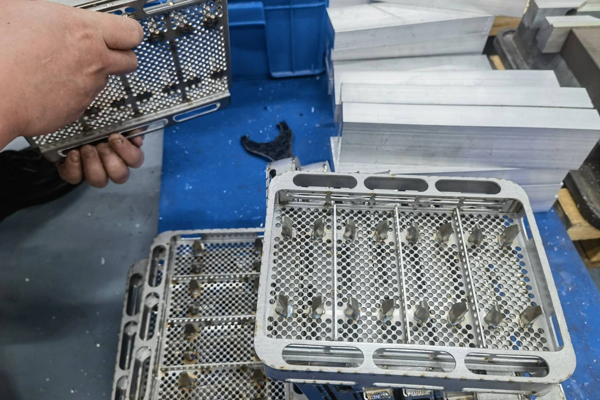

Sheet metal assembly joins separately cut and formed metal parts into an enclosure, bracket assembly, panel, or frame. The core design work happens joint by joint: decide what each connection needs to do, then check that the design gives the chosen method the fit, tool access, and assembly order it needs.

Start With the Assembly’s Function
Pick the joining method for each interface, not once for the whole assembly. A single enclosure can mix methods, such as a welded internal frame with access panels held on by screws.
Take an equipment enclosure with three interfaces:
- The internal support stays in place, so it can take a permanent joint if its load and material requirements allow.
- The cover has to come off, so technicians need a connection they can release.
- The mounting panel carries the equipment, so its holes and seating surfaces need to be positioned relative to that equipment.
Note the load path, removal needs, and locating features for each interface on the assembly drawing. The manufacturer can then review those decisions in one place instead of piecing them together from separate part drawings.
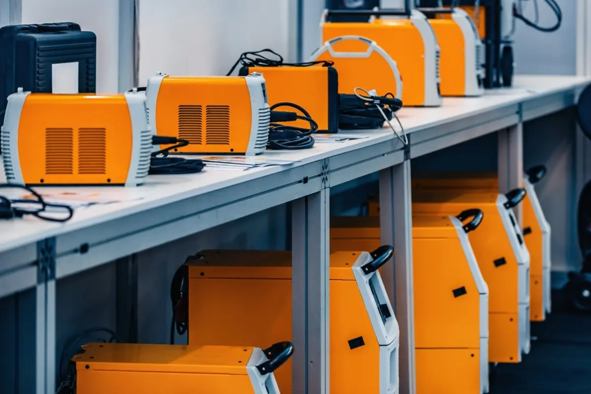
Choose the Joining Method
Start with one question: does this joint ever need to come apart? Welding and riveting make permanent joints, while screws and bolts can be opened again. That answer narrows the list fast, but material compatibility, joint geometry, and installation access decide whether a method will actually work.
Welded joints
Welding fits a fixed bracket or frame when the material, joint design, and weld requirements support a permanent joint. TIG and MIG welding fuse the joint with an electric arc. Resistance spot welding works differently: current passes through overlapping sheets clamped between electrodes, and resistance heating plus electrode pressure form a local joint.
Each process asks something different of the design. An arc-welded seam needs room for the welding tool and proper joint preparation. A conventional spot-welded lap joint needs overlapping material and space for the electrodes. And wherever a nearby face or hole controls how the assembly fits, plan for heat-related movement.
Riveted joints
Rivets join parts without welding heat. That matters when you compare riveting vs welding for a panel where fit is critical. A rivet holds the layers together by deforming the fastener itself.
Blind rivets are set from one side with a mandrel, so they’re an option where you can reach only one side of the joint. One catch: the rivet body still needs room behind the sheet to form correctly.
Before you specify a rivet for a fixed panel, check the rivet manufacturer’s hole preparation and grip range, which is the range of total material thickness the rivet can join. Leave clearance for both the head and the formed end.
Think about service, too. Removing a rivet destroys it, so a panel that opens for routine maintenance should get a removable connection.
Screw and bolt connections
Use screws or bolts anywhere a cover, panel, or bracket has to come off or be adjusted. The design needs a threaded attachment and enough room to install and remove the fastener. With a loose nut, someone also has to hold the nut while the screw turns, so leave room to reach it.
Thin sheet may not offer enough thread engagement on its own. Two types of hardware can add it:
- A self-clinching nut is pressed into a prepared hole, and the sheet material flows into the nut’s retaining feature.
- A rivet nut is set by deforming its body, and it can be installed from one side.
Treat these as two separate jobs in the design review: getting the nut into the sheet, then fastening the mating part with a screw. The nut stays put when the screw comes out.
Clinching performance depends on the details. PennEngineering’s design data ties it to the specific fastener, sheet material, thickness, hardness, hole preparation, and installation tooling, so take dimensions and installation conditions from the documentation for the hardware you actually select.
Compare Methods Against the Same Requirements
The table screens each method on disassembly, access, and what the design has to provide. Joint strength and cost aren’t in the table. Both depend on the actual material, geometry, loading, and production plan, so compare them against your real design.
| Method | Disassembly | Installation access | Design provisions | Confirm during review |
|---|---|---|---|---|
| TIG or MIG welding | Permanent | Welding tool and fixture access | Joint preparation, weld location, fit-up, and clamping features | Material suitability, weld requirements, distortion, and finished fit |
| Resistance spot welding | Permanent | Electrode access to the selected lap joint | Overlap and electrode contact areas | Sheet combination, tooling reach, weld arrangement, and joint performance |
| Blind riveting | Rivet destroyed for removal | Setting tool on one side; space for the formed rivet behind | Prepared holes, suitable joined thickness, and head clearance | Rivet type, grip range, hole conditions, and load suitability |
| Screws or bolts | Removable | Driver access; nut access if loose | Threaded attachment, mating-hole fit, and removal path | Thread engagement, hardware installation, and tightening requirements |
Check Location, Fit, and Tool Access
Run these checks on the formed assembly, with any installed hardware in place.
Locating features and mating interfaces
Decide which surfaces, holes, or slots actually set each part’s position. Use the functional mounting interface as the datum, the reference you locate and measure other features from, and check hole position, panel gaps, and bracket position against it.
Then keep location and clearance apart. A locating feature fixes position; a clearance hole just lets the fastener through. If every hole is drawn as a close-fitting locator, small differences across parts can add up, and the assembly becomes sensitive to that accumulated variation.
Thin parts also flex under clamping and joining loads. In a compliant (flexible) sheet metal assembly, part tolerances and fixture layout both shape the finished geometry.
Check tab-and-slot fit on the finished features, after cutting, forming, and surface treatment. Confirm tolerances for each critical interface with the manufacturing team.
Installation Access and Assembly Order
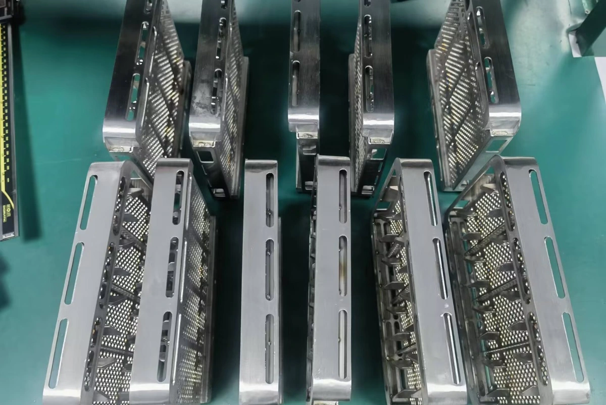
Access problems are easy to miss in CAD. The fastener head sits right there on screen, but the driver body, rivet-tool nose, press anvil, or welding electrode may not be able to reach it.
Walk through the assembly sequence in the model, one step at a time, and check that:
- each tool can approach the joint and back out again
- closing a side panel doesn’t block access to an internal nut (if it does, tighten that connection before closure or change the attachment)
- clinching hardware has room for the installation punch and anvil, which may mean installing it at a different stage from the final screw fastening
- a service panel can move clear of neighboring flanges once its screws are out
Plan Welded Joints Around Distortion
Ask for the weld the joint needs and no more, then settle weld placement and sequence with the manufacturer. Weld placement, fit-up, clamping, and sequence all influence distortion, and TWI’s design guidance links excess weld metal and poor fit-up to greater shrinkage and distortion.
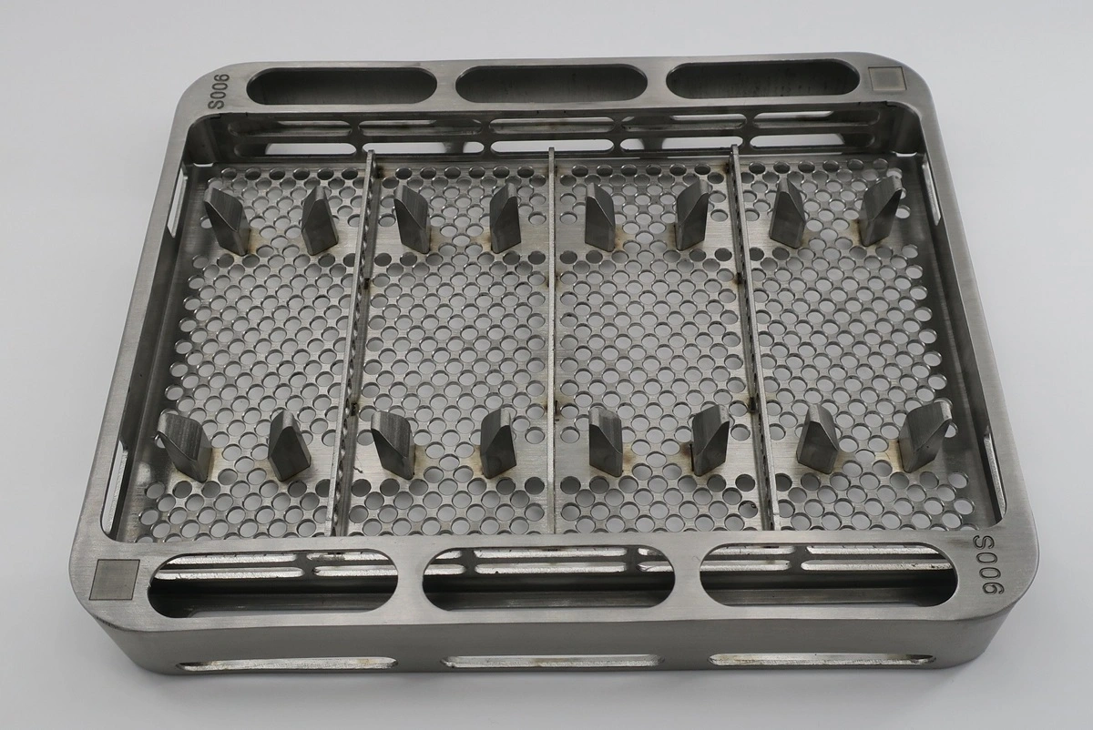
Thin parts make the problem easy to see. We ran into it on a dental sterilization tray project: 0.06 in. (about 1.5 mm) sheet with 16 tack-welded locating pins. Weld distortion shifted the pin positions, so the tray still fit but no longer located the instruments correctly.
The customer had already gone through five sampling rounds with other suppliers without success. We locked pin location and perpendicularity in a fixture before welding, used a balanced welding sequence with distributed heat input, controlled cooling and clamp release, and checked pin placement during setup instead of only after assembly. That approach resolved the issue in two sampling iterations.
A few points to raise with your manufacturer:
- Balanced welding. Where the geometry allows, spreading welds around the joint can counter angular movement. The right sequence still depends on access, joint form, material, and the result you need.
- Intermittent welds. Check them against what the joint has to do. They aren’t an automatic substitute for a continuous seam.
- Clamp release. A fixture holds parts during joining, but a compliant assembly can move once the clamps come off. Check mounting surfaces and mating holes on the released assembly as part of welding warpage control.
Match the Assembly Plan to the Manufacturer
Before you release the design, make sure every joint you’ve specified matches a process the manufacturer documents. The same conversation is the right time to agree on which parts and assembly steps belong in the quote.
Fabrication and Welding Scope
At Rollyu Precision, we provide laser cutting, press-brake bending, and TIG, MIG, and spot welding, plus assembly support for custom sheet metal components. Engineering and design for manufacturability (DFM) review is the first step in our production workflow.
Send the formed assembly model and its critical interfaces with your quote request. During that review, our engineers can confirm the welding process for your material, thickness, and joint.
Hardware and Delivery Scope
If the design uses blind rivets, self-clinching nuts, or rivet nuts, list them in your quote request so the quotation can spell out which installation operation is included, who supplies the hardware, and what the inspection covers.
Tell us what you need to receive, too: loose fabricated parts, a joined metal subassembly, or another configuration agreed for the project. Electrical installation, system integration, and equipment commissioning are outside the scope unless the quotation explicitly includes them.
Prepare the Assembly for Manufacturing Review
Send the assembly requirements along with the part geometry when you request a sheet metal fabrication quote. We can only quote what we can see, so include:
- Assembly model and part drawings with matching revisions, material grades, thicknesses, and quantities
- A bill of materials that separates fabricated parts, purchased hardware, and anything your team will supply
- Joint locations and proposed methods, with removable interfaces marked apart from permanent connections
- Critical assembled dimensions, locating references, mating interfaces, and the inspection conditions that matter to function
- Finish requirements, visible surfaces, and any areas where coating could affect fit or hardware installation
- Your open questions on tool access, installation order, weld distortion, hardware choice, and delivery scope
Mark anything that’s still a proposal so our engineers know to review it. During DFM review, we can confirm the joining methods and flag drawing changes or open assembly questions with the quote. Once those decisions are agreed, update the assembly drawing and bill of materials before release.
If you have an assembly in progress, send the model, drawings, and bill of materials with a quote request, and we’ll start with the DFM review.
Frequently Asked Questions
Can aluminum panels be joined with stainless steel fasteners?
Yes, but check for galvanic corrosion first. Dissimilar metals in electrical contact can corrode when an electrolyte, such as salt water, is present. Choose the hardware and protection for the operating environment, and where exposure makes corrosion a real concern, review electrical isolation and coating condition.
How do you keep screws from loosening in a vibrating assembly?
Start with clamping force, then choose a locking approach that fits the joint’s actual loading and service needs. Vibration and transverse (sideways) movement can make threaded connections lose preload. Confirm the tightening conditions and validate the arrangement on the assembly itself; no single washer or locking feature suits every joint.
Does riveting make a sheet metal enclosure watertight?
Not on its own. Sealed rivet designs deal with the fastener connection, but panel seams and other openings are separate leak paths. Define the sealing performance you need, then confirm the full enclosure design and test scope with the manufacturer.
