

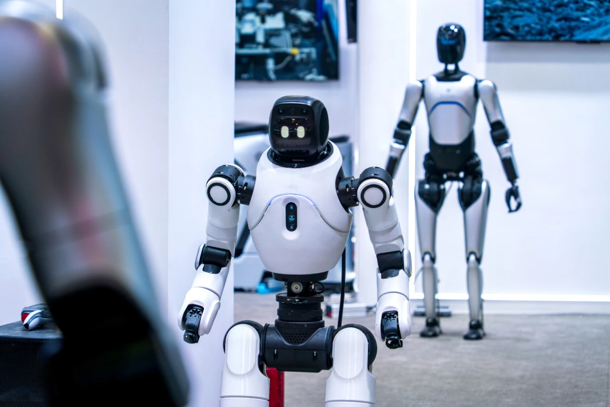
Robot joints, transmission systems, sensor mounts, and lightweight structures depend on precisely machined components to maintain motion accuracy, rigidity, and reliable assembly. CNC machining for robots is well suited to complex geometries, tight tolerances, and low-volume production. This guide explains common robot parts, material selection, machining methods, process planning, quality control, and the key factors to consider when choosing a manufacturing partner.
What Is CNC Machining for Robots?
CNC machining for robots is the production of precision mechanical components used in robotic motion, transmission, sensing, structural support, and end-effector assemblies. It combines programmable machining with controlled setups and inspection to produce parts that meet functional assembly requirements.
How CNC Machining Supports Robotic Systems
CNC milling produces complex housings, brackets, pockets, mounting faces, and accurate hole patterns, while CNC turning is suited to shafts, pins, sleeves, and bearing interfaces. Mill-turn machining can complete rotational and off-axis features in fewer setups, and multi-axis machining improves access to angled faces and complex robotic CNC components. Together, these processes support tight fits, motor and bearing interfaces, and flexible production from engineering prototypes to low-volume or repeat orders.
Why Robotics Requires More Than General CNC Machining
Robot precision parts cannot be evaluated by isolated dimensions alone. A joint housing may require a controlled coaxial relationship between the motor bore and bearing seat, while a sensor base may depend on flatness, perpendicularity, and accurate datum relationships. These controls affect assembly alignment, friction, vibration, motion accuracy, and repeatability. Tolerances should therefore be assigned according to each interface and the complete assembly rather than tightened indiscriminately.
Which Robot Parts Are Commonly CNC Machined?
CNC machining is used across robotic joints, motion systems, structural assemblies, sensors, and end effectors. Each group has different functional requirements, so the machining strategy should reflect how the component carries load, locates adjoining parts, or influences movement.
Joint Housings and Motor Mounts
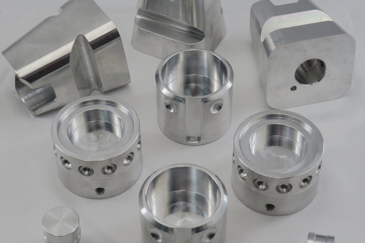
Rotary and linear joint housings, servo motor mounts, harmonic reducer interfaces, bearing seats, and encoder mounts are commonly CNC machined. Their performance depends on accurate hole patterns, controlled mating faces, and reliable bearing fits. Coaxiality between motor, reducer, and bearing interfaces is especially important because misalignment can increase friction, vibration, wear, and assembly difficulty.
Transmission and Motion Components
Typical motion components include shafts, couplings, pulleys, gearbox housings, ball-screw supports, and planetary roller-screw interfaces. CNC turning, milling, and mill-turn machining can establish mounting features, journals, bores, and datum surfaces. However, gears, ball screws, and planetary roller screws may also require specialized grinding, rolling, heat treatment, or finishing processes beyond conventional CNC machining.
Structural and Lightweight Components
Robot arms, limb connectors, torso frames, end-effector bodies, lightweight brackets, and thin-wall housings must balance strength, rigidity, and low mass. Excessive material increases inertia, while aggressive weight reduction can make the part vulnerable to machining and clamping deformation. Toolpaths, workholding, and machining sequence should therefore preserve rigidity while achieving the required wall thickness.
Sensor, Vision and End-Effector Components
Force-torque sensor mounts, camera mounts, calibration plates, gripper bodies, and tool-changing interfaces rely on accurate mounting datums and hole positions. Flatness and perpendicularity help sensors and cameras maintain alignment, while controlled interface geometry supports repeatable positioning during gripper changes, calibration, assembly, and operation.
| Robot system | CNC-machined parts | Critical requirements | Common materials |
| Joints | Housings, motor mounts | Axis alignment, bearing fits | 6061, 7075, steel |
| Motion systems | Shafts, couplings | Runout, shaft alignment | Steel, stainless steel |
| Structures | Arms, frames | Weight, rigidity | Aluminum, titanium |
| Sensors | Mounts, baseplates | Flatness, position | Aluminum, stainless steel |
| End effectors | Grippers, interfaces | Repeatability, alignment | Aluminum, steel |
What Materials Are Used for Robot CNC Parts?
Material selection for robot CNC parts should reflect load, weight, rigidity, temperature, wear, corrosion, electrical requirements, and operating environment. The best material is not always the strongest one; it must also support practical machining, stable tolerances, surface treatment, and assembly.
Aluminum 6061 and 7075
Aluminum 6061 is widely used for robot frames, housings, brackets, motor mounts, and general structural components because it offers good machinability, corrosion resistance, and finishing options. Aluminum 7075 provides substantially higher strength and is suitable for heavily loaded arms, joint structures, and compact components where weight reduction matters. However, its elastic modulus is not dramatically higher than that of 6061, so part geometry still strongly influences stiffness. Both alloys require controlled machining sequences and workholding when thin walls, deep pockets, or residual stress create distortion risks.
Stainless Steel and High-Strength Steel
Stainless steel is commonly selected for shafts, connectors, corrosion-resistant structures, precision interfaces, and components exposed to demanding environments. Alloy and high-strength steels are better suited to loaded shafts, transmission parts, bearing surfaces, and wear-resistant mechanisms. Compared with aluminum, these materials generate more cutting heat and tool wear. Some steel components also require heat treatment, grinding, surface hardening, or hardness verification to achieve their final mechanical and dimensional requirements.
Titanium and Engineering Plastics
Titanium combines high strength, low density, and corrosion resistance, making it useful for lightweight structures and demanding robotic environments, although concentrated cutting heat increases machining difficulty. Engineering plastics such as PEEK, POM, and UHMW can serve as insulators, guides, sliding elements, wear strips, and low-friction components. Their selection should consider temperature, load, moisture, dimensional stability, and friction rather than machinability alone.
| Material | Main advantage | Machining concern | Typical robot parts |
| Aluminum 6061 | Machinability and corrosion resistance | Thin-wall distortion | Housings, brackets |
| Aluminum 7075 | Higher strength | Residual stress | Arms, joint structures |
| Stainless steel | Strength and corrosion resistance | Heat and tool wear | Shafts, interfaces |
| Alloy steel | Load and wear resistance | Heat-treatment distortion | Transmission parts |
| Titanium | Strength-to-weight ratio | Heat concentration | Lightweight structures |
| Engineering plastics | Insulation and low friction | Burrs and deformation | Guides, insulators |
Which CNC Processes Are Used for Robot Parts?
Robot components vary from simple mounting plates to multi-axis joint housings and precision shafts. The appropriate CNC process depends on geometry, feature direction, tolerance relationships, production quantity, and the number of setups needed to complete the part reliably.
CNC Milling and 5-Axis Machining
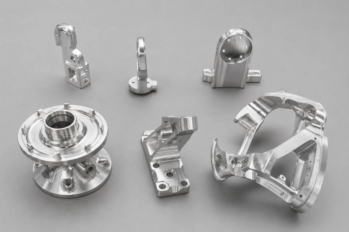
Three-axis milling is suitable for flat surfaces, holes, slots, pockets, and structural parts whose main features can be reached from conventional orientations. For features located in several directions, 3+2 machining and 5-axis machining provide different levels of tool access and motion control. In 3+2 machining, the workpiece is indexed to a fixed angle before cutting, allowing shorter, more rigid tools to reach angled features. Simultaneous five-axis machining is better suited to complex surfaces, inclined interfaces, deep features, and parts that benefit from fewer setups. However, not every robot part requires five-axis machining. A stable three-axis or 3+2 process may be more economical when the geometry and tolerance relationships do not require simultaneous five-axis motion.
CNC Turning and Mill-Turn Machining
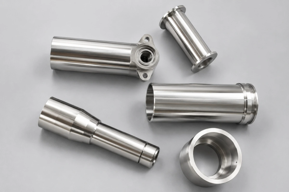
CNC turning is commonly used for robot shafts, pins, sleeves, couplings, bearing interfaces, and threaded connectors. It efficiently controls diameters, shoulders, grooves, threads, and concentric rotational features. Mill-turn machining adds off-axis holes, flats, slots, or milled interfaces without transferring the part to a separate machine. Reducing re-clamping can improve the positional relationship between turned and milled features, especially on actuator shafts, couplings, and compact transmission components.
Secondary Processes and Surface Finishing
Robot parts may also require grinding, EDM, heat treatment, anodizing, passivation, plating, bead blasting, or laser marking. Grinding can refine critical bearing or shaft surfaces, while EDM supports narrow slots and features that are difficult to cut conventionally. Heat treatment changes mechanical properties but may also cause distortion. Coatings and finishes can alter hole sizes, shaft diameters, threads, electrical contact areas, and mating fits. These effects should be considered before machining through dimensional compensation, masking instructions, allowance planning, and final-condition inspection.
How Should the Machining Sequence Be Planned?
The machining sequence for a robot part should be based on its geometry, blank condition, tolerance relationships, workholding options, and final inspection requirements. Rules such as “machine cavities before the outside” can be useful starting points, but the final sequence must protect stable datums, workpiece rigidity, and functional interfaces.
Machine Stable Datums and Positioning Surfaces First
Early operations should establish reliable datum and positioning surfaces that can support later setups. Features such as hole patterns, bearing seats, motor interfaces, and mating faces can then be machined relative to the same controlled references. This does not always mean machining every flat surface before every hole. The correct order depends on which features locate the part during production and which datum relationships control its assembly.
Protect Workpiece Rigidity Throughout Machining
Features that cause little loss of rigidity should generally be completed before large cavities, deep pockets, and thin walls weaken the workpiece. Temporary ribs, support stock, or sacrificial tabs may remain during roughing to reduce deflection. After major material removal, intermediate inspection, stabilization, or stress relief may be appropriate. Critical bearing bores and mating surfaces are then finish-machined after the part reaches a more stable condition.
Reduce Re-Clamping and Datum Transfers
Operations using the same datum system, fixture, and clamping method should be grouped when practical to limit repositioning error. Multi-axis machining can complete several faces without unnecessary transfers when it improves access or preserves critical relationships. If re-clamping is unavoidable, the process plan should define repeatable locating surfaces and verify each new setup against the controlling datums.
Tool-Based and Feature-Based Sequencing
Tool-based sequencing completes suitable features with one tool before loading the next, while feature-based sequencing groups planes, holes, cavities, curved surfaces, or profiles. Neither method is universally better. The choice should reflect tool life, changeover time, chip evacuation, rigidity, dimensional relationships, and the needs of later clamping and inspection.
What Makes Robot Precision Parts Difficult to Machine?
Robot precision parts often combine low weight, complex geometry, tight fits, and multiple functional interfaces. These requirements create machining risks that cannot be solved by tighter dimensional tolerances alone. Workholding, tool access, material stability, process repeatability, and inspection must be planned together.
Thin Walls and Lightweight Structures
Thin-wall robot frames, arms, and housings can deform under clamping pressure or cutting forces. Residual stress may also move the part during material removal or after unclamping, causing wall-thickness variation and dimensional change. Soft jaws, internal supports, symmetrical roughing, controlled material removal, and multiple semi-finishing stages help maintain rigidity before final machining.
Coaxial Relationships and Bearing Fits
Joint housings, motor mounts, bearing seats, and reducer interfaces often share a common rotational axis. Independent diameter tolerances do not fully control their alignment. Depending on the functional relationship, datum-based position, circular runout, total runout, and perpendicularity controls may be used to manage alignment between bores, shafts, motor pilots, and reducer interfaces. The appropriate control should follow the assembly and motion requirements rather than be applied as a generic tolerance.
Deep Cavities and Multi-Direction Features
Deep pockets and features located on several faces can limit tool access and require long tool overhangs. Reduced tool rigidity increases vibration, deflection, poor surface finish, and dimensional variation, while restricted cavities make chip evacuation more difficult. Shorter tools, staged machining, suitable toolpaths, and multi-axis access can reduce these risks. If several setups are necessary, reliable datum transfer is essential to prevent positional error.
Prototype Accuracy vs Batch Consistency
A successful prototype does not prove that the same process will remain stable across repeated batches. Tool wear can change dimensions and surface quality, while fixture variation, thermal drift, and differences between material lots can shift critical features. Batch production therefore requires controlled programs, repeatable workholding, tool-life management, and risk-based in-process inspection. Buyers should evaluate whether a supplier can maintain critical dimensions over time, not only whether one sample passes final inspection.
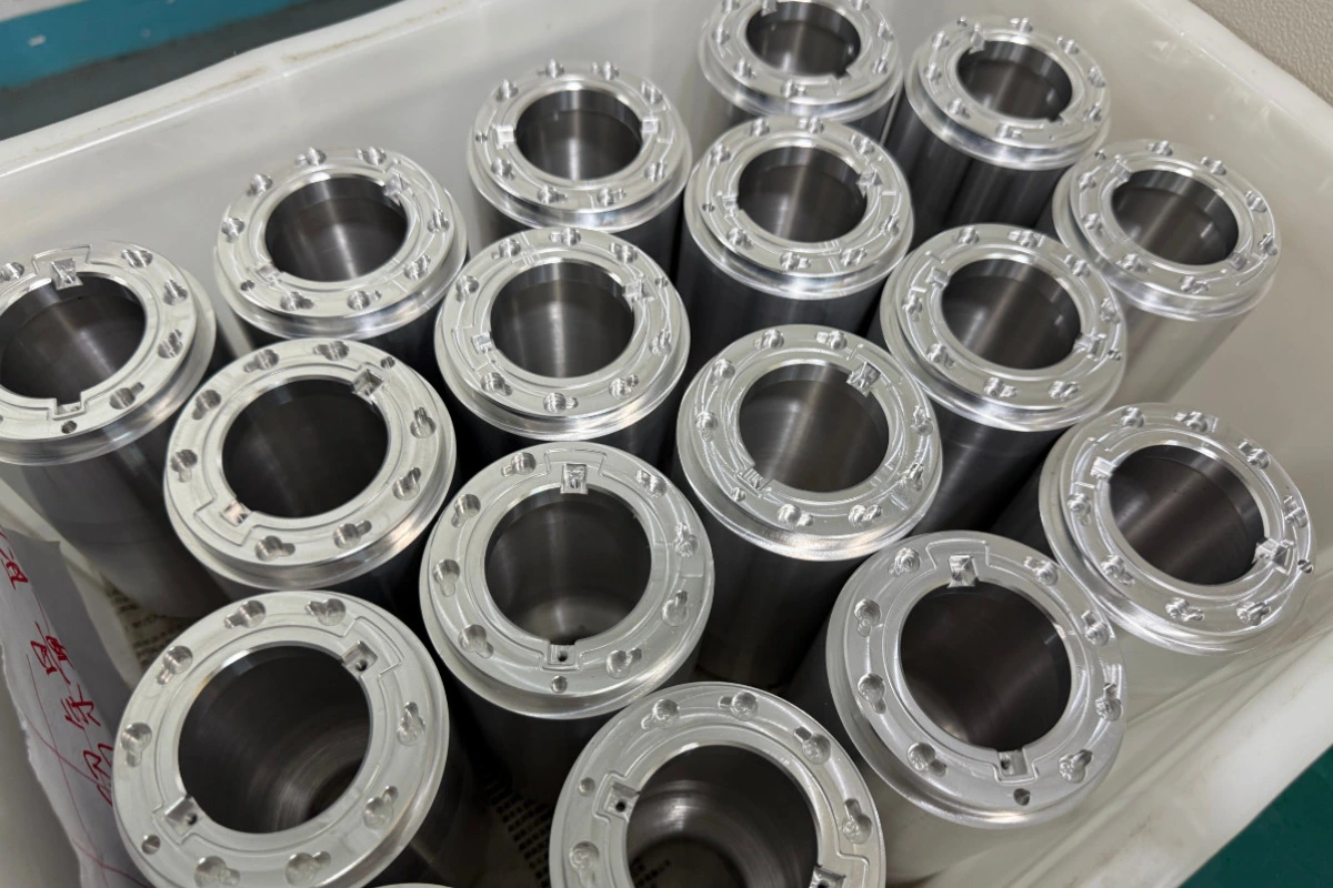
How Are CNC-Machined Robot Parts Inspected?
Inspection should verify the dimensions and geometric relationships that affect assembly, movement, load transfer, and repeatability. The inspection method should match the feature, tolerance, production stage, and documentation required by the customer.
Dimensional and Geometric Inspection
A CMM is useful for datum-based position, flatness, perpendicularity, and other geometric relationships, but it is not the best tool for every feature. Micrometers measure external sizes, bore gauges check internal diameters, height gauges evaluate features from a reference surface, and thread gauges verify threaded interfaces. Roughness testers assess functional surfaces, while optical systems support small profiles, edges, and non-contact measurement. The instrument should match the feature and tolerance.
First Article and In-Process Inspection
First article inspection helps confirm that the process, setup, material, and drawing interpretation can produce an acceptable part before the batch proceeds. In-process checks can detect tool wear, fixture movement, or thermal drift before they affect multiple components. Their frequency should reflect feature risk, batch size, process capability, and customer requirements rather than an arbitrary interval. Final inspection verifies the released acceptance criteria and required records.
Material and Quality Documentation
Documentation should be defined before production because each robot project requires different evidence. Depending on the drawing, purchase order, and quality plan, the package may include a material or mill test report (MTR), certificate of conformance (COC), FAI report, CMM report, surface-treatment certificate, heat-treatment certificate, and lot-traceability records. Each document should identify the correct part number, revision, material lot, and production batch.
How Do Robot Parts Move From Prototype to Production?
Moving from prototype to production requires more than increasing order quantity. Each stage should reduce technical uncertainty while confirming that the machining, inspection, and assembly process can remain stable.
Prototype and DFM Review
The prototype stage should evaluate material selection, tool access, wall thickness, corner radii, tolerance feasibility, inspection access, and surface finishing. DFM review identifies features that may increase distortion, setup complexity, cost, or measurement difficulty before the design is released.
Low-Volume Pilot Production
A pilot batch verifies fixture design, cycle time, tool life, process repeatability, and assembly compatibility under realistic production conditions. It can reveal variation that may not appear in a single prototype and provides evidence for adjusting workholding, toolpaths, or inspection controls.
Scaling Without Losing Consistency
Stable production requires controlled CNC programs, revision management, repeatable fixtures, approved inspection plans, material traceability, and formal change control. These controls allow production volume to increase without losing the dimensional consistency established during prototype and pilot stages.
How to Choose a CNC Machining Supplier for Robot Parts
A supplier should be evaluated by its ability to understand the robot assembly, control critical features, maintain batch consistency, and respond to engineering changes. Price and machine specifications alone do not demonstrate these capabilities.
Relevant Robotics and Precision-Machining Experience
Ask whether the supplier understands assembly tolerance chains, bearing and motor interfaces, lightweight structures, multi-axis motion components, and design changes between prototype and production. Relevant engineering experience matters more than simply claiming to have manufactured “robot parts.”
Proven Precision and Process Capability
Review similar parts, inspection reports, materials, workholding methods, and critical-dimension controls. Confirm that the supplier can maintain results across a batch, not only on one sample. Machine specifications describe equipment potential, but they do not prove process stability.
Quality System and Traceability
Check applicable ISO certifications, material control, revision management, FAI and inspection records, nonconformance handling, and lot traceability. These controls should connect each delivered part to the correct drawing revision, material lot, production batch, and inspection result.
Engineering Response and Delivery Capability
Evaluate the quality of DFM feedback, clarity of quotation assumptions, prototype and production lead times, and response to engineering changes. For robotics programs, the supplier should also demonstrate practical support for high-mix, low-volume production and repeat orders.
| Evaluation area | What to verify | Warning sign |
| Precision | Similar parts and reports | Only machine specifications |
| Robotics experience | Assembly and motion interfaces | Generic capability claims |
| Quality | FAI, traceability, revision control | No documented process |
| Scalability | Prototype-to-production plan | Sample success only |
| Communication | Clear DFM and assumptions | Quote without technical review |
CNC Machining for Industrial, Collaborative and Humanoid Robots
Different robot platforms use many of the same machining processes, but their components vary in size, load, weight, safety requirements, and operating environment. The part design and manufacturing plan should reflect the function of each robot type.
Industrial and Collaborative Robots
Industrial and collaborative robots commonly use CNC-machined joint housings, reducer interfaces, robot arms, end-effectors, safety sensor mounts, and cable-routing components. These parts require reliable alignment, structural rigidity, and repeatable assembly. Collaborative systems may also place greater emphasis on compact geometry, low weight, smooth external surfaces, and integrated sensing.
Mobile Robots and AMRs
Mobile robots and autonomous mobile robots use machined wheel hubs, motor mounts, sensor brackets, LiDAR mounts, battery frames, and chassis components. These parts must maintain sensor alignment and drivetrain positioning while resisting vibration, impacts, and repeated movement. Lightweight aluminum structures are common, although loaded shafts, hubs, and interfaces may require steel or stainless steel.
Humanoid Robot Parts
Humanoid robots combine compact joint housings, limb structures, torque-sensor mounts, actuator components, lightweight frames, and hand or gripper parts. Their architecture varies between designs, so no fixed joint count applies universally. CNC machining supports the close integration of motors, reducers, bearings, sensors, and structural components while balancing strength, available space, weight, and motion accuracy.
Why Choose Rollyu for Robot CNC Machining?
Rollyu Precision supports robot component projects that require complex geometry, controlled tolerances, documented inspection, and flexible production volumes. Its services cover the engineering and manufacturing stages from prototype review to low-volume production.
Precision CNC Machining Capabilities
Rollyu provides five-axis CNC machining, CNC turning, and mill-turn machining for thin-wall and complex robot parts. Supported materials include aluminum, stainless steel, titanium, and engineering plastics. These capabilities cover housings, mounts, shafts, interfaces, brackets, and other components from prototypes to low-volume batches.
Inspection and Documentation
Rollyu Precision is certified to ISO 9001:2015 and ISO 13485:2016. Depending on project requirements, quality records can include CMM results, first article inspection reports, material or mill test reports, certificates of conformance, dimensional inspection reports, and lot-traceability documentation.
Engineering Support From Prototype to Low-Volume Production
Engineering support includes DFM review, fixture and process planning, critical-tolerance review, and coordination of surface-finishing requirements. This approach helps identify machining, distortion, measurement, and final-fit risks before production while supporting controlled transition from prototypes to repeat low-volume orders.
Frequently Asked Questions About CNC Machining for Robots
What Robot Parts Can Be CNC Machined?
Common CNC-machined robot parts include joint housings, motor mounts, shafts, couplings, arms, sensor bases, gripper bodies, and tool-changing interfaces. Suitability depends on the geometry, material, tolerance, and production volume.
Which Material Is Best for CNC Robot Parts?
There is no universal best material. Aluminum suits lightweight structures, steel supports high loads and wear, titanium combines strength with low weight, and engineering plastics provide insulation or low friction.
Do Robot Parts Always Require 5-Axis Machining?
No. Three-axis machining is often sufficient for simple plates, brackets, holes, and pockets. Five-axis machining is most useful when complex geometry, angled features, or critical relationships justify fewer setups.
How Tight Should Tolerances Be for Robot Parts?
Tolerances should reflect fit, alignment, motion, sealing, or sensor performance. Applying unnecessarily tight tolerances to noncritical dimensions increases machining and inspection cost without improving function.
How Can Thin-Wall Robot Parts Be Machined Without Distortion?
Common methods include soft jaws, internal support, balanced material removal, controlled cutting forces, and staged roughing and finishing. The machining sequence should preserve rigidity until critical surfaces are finished.
What Inspection Reports Are Needed for Robot Components?
Requirements may include FAI, dimensional inspection, CMM results, MTR, COC, and surface- or heat-treatment certificates. The required documents should be defined on the drawing, purchase order, or quality plan.
How Do You Choose a CNC Supplier for Robotics Projects?
Review relevant parts, inspection reports, process controls, quality systems, DFM capability, and batch consistency. Do not select a supplier based only on quotation price or machine specifications.
Request a DFM Review for Your Robot CNC Parts
Send your robot-part 3D model and 2D drawing to Rollyu Precision for an engineering review. Include the required material, critical tolerances, quantity, surface finish, and inspection or documentation requirements. Our team can review machining access, tool and fixture considerations, thin-wall or distortion risks, tolerance feasibility, measurement access, and finish-related dimensional changes. This early review helps clarify technical requirements before quotation and supports a more controlled transition from prototype machining to repeat low-volume production.
