

ULTEM machining is the CNC milling, turning, drilling and finishing of polyetherimide (PEI) stock into precision functional parts. ULTEM is SABIC’s trade name for a family of amorphous PEI resins; the family includes unfilled and reinforced grades that differ substantially in stiffness, tool wear, surface behavior and dimensional response. For buyers, the practical question is not simply whether ULTEM can be machined. It is whether the exact grade, stock form, geometry, tolerance scheme and service environment can be matched to a controlled machining route.
This guide is written for engineers and procurement teams sourcing ULTEM plastic machined parts for medical devices, aerospace hardware, electronics, photonics, automation and other high-performance equipment. It focuses on the manufacturing decisions that affect fit, surface condition and repeatability: grade selection, machinability, tooling, reference speeds and feeds, heat and moisture control, optional stress-relief annealing, inspection and drawing-specific risk control. It also explains why a supplier should not advertise one universal tolerance, one mandatory annealing cycle, or one set of cutting parameters for every ULTEM part.
What Is ULTEM and Why Is It Used for CNC Machined Parts?
ULTEM is an amorphous high-performance PEI thermoplastic known for its balance of elevated-temperature capability, mechanical strength, electrical insulation and inherent flame resistance in many grades. Because the polymer is amorphous rather than semi-crystalline, it softens through a glass-transition region instead of behaving like a material with a sharp crystalline melting point. That distinction matters in both design and machining: localized cutting heat can change dimensions or surface condition well before the material is chemically degraded.
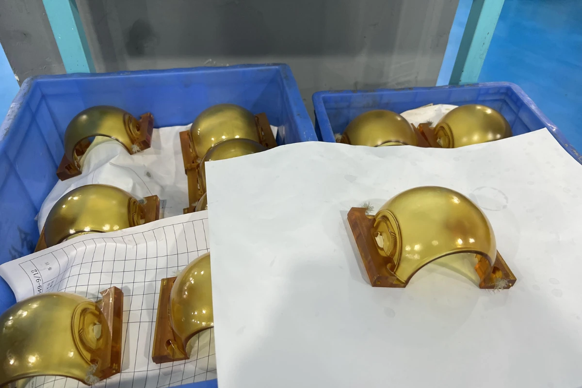
ULTEM 1000 is an unreinforced PEI grade and is usually the first reference point for CNC work because it offers a comparatively clean cutting response and a translucent amber appearance. ULTEM 2300 contains 30% glass fiber and raises stiffness and dimensional stability under load, but the glass reinforcement is abrasive and can make drilling exits, sharp corners and cosmetic surfaces less forgiving. ULTEM 2400 contains 40% glass fiber and pushes stiffness further; its fiber orientation and anisotropic thermal expansion become more important in stock selection, toolpath planning and final inspection. The correct grade should therefore be specified on the purchase drawing or material specification rather than inferred from color alone.
| Grade | Reinforcement | Machining implication | Typical reason to select |
| ULTEM 1000 | Unfilled | Cleaner cutting and lower abrasive wear; still heat/stress sensitive | Electrical insulation, translucent functional parts, balanced PEI properties |
| ULTEM 2300 | 30% glass fiber | More abrasive; monitor tool wear and breakout | Higher stiffness and dimensional stability under load |
| ULTEM 2400 | 40% glass fiber | Highest reinforcement of these examples; fiber orientation matters | High stiffness, creep resistance and thermally stable structural parts |
ULTEM Machinability: Heat, Stress and Chip Control
ULTEM is machinable, but it should be treated as an engineering thermoplastic rather than as a soft metal. Three effects dominate process planning. First, plastics conduct heat slowly, so a dull edge or rubbing tool can concentrate heat in a small zone. Second, molded or extruded stock can contain residual stress; large or unbalanced material removal can release that stress and move a thin wall, flat plate or deep pocket. Third, glass-filled grades are abrasive, so tool condition can deteriorate faster than on unfilled PEI and surface finish can drift before a dimension is obviously out of tolerance.
A robust route typically removes stock symmetrically where possible, uses sharp cutting edges, avoids excessive clamping pressure, clears chips promptly, and separates roughing from critical finishing when the geometry is distortion-sensitive. For a deep cavity or a thin flat component, rough machining can leave uniform finishing allowance, after which the part is allowed to cool and relax before the final datum and critical features are cut. This is often more reliable than trying to finish every feature immediately after heavy stock removal.
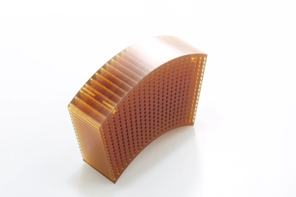
Unfilled ULTEM 1000 generally provides the best combination of machinability and edge quality. ULTEM 2300 and 2400 reward rigid workholding and wear-resistant tooling, but they also require more attention to exit chipping and fiber breakout. Small holes and dense hole patterns deserve a dedicated drilling strategy because chip packing and repeated heat input can influence both diameter and positional stability.
Tooling for ULTEM 1000, 2300 and Glass-Filled PEI
For unfilled PEI, sharp micrograin carbide is a dependable default for milling, turning and drilling. High-speed steel may work for a very short prototype operation, but carbide usually gives more consistent edge condition and tool life. Use positive, free-cutting geometry and enough clearance to cut rather than rub. Highly honed or edge-prepared metal tools can generate more heat in plastic than a purpose-selected sharp plastic-machining edge.
For glass-filled ULTEM 2300 or 2400, the filler changes the economics. Carbide can still be suitable for short runs and flexible production, but PCD or CVD-diamond tooling may be justified when tool wear, repeatability or surface finish dominates cost. Tool selection should be based on the actual grade, feature size, expected volume and permitted edge condition; saying that every glass-filled ULTEM part ‘requires PCD’ would be as inaccurate as saying ordinary carbide always lasts long enough.
Drills should evacuate chips cleanly and avoid prolonged dwell. Pecking or staged drilling can be useful for deep or small-diameter holes, especially when a dense pattern concentrates heat in a small part. Backup support can reduce breakthrough damage. In milling, shorter tool overhang and balanced engagement help keep cutting forces predictable. In turning, a sharp nose radius should be chosen to support the required finish without pushing a thin wall away from the tool.
Speeds and Feeds for ULTEM Machining
The safest way to publish speeds and feeds for ULTEM machining is as a starting window, not a recipe. A cutting speed is more portable than a raw spindle RPM because RPM changes with tool diameter. Mitsubishi Chemical Advanced Materials publishes PEI stock-shape machining guidance that provides useful reference ranges for unfilled PEI and reinforced PEI-like materials; those values should still be validated on the actual ULTEM grade, stock source, tool geometry, machine and part geometry.
Convert surface speed to spindle speed with RPM = (1000 x Vc) / (pi x D), where Vc is cutting speed in m/min and D is tool diameter in mm. Then set feed from the cutter geometry and chip load or from feed per revolution for turning/drilling. A 6 mm end mill and a 20 mm end mill should not be assigned the same RPM simply because both are cutting ULTEM.
For first articles, start conservatively, verify chip formation and temperature, and adjust one variable at a time. A stable chip, clean edge, controlled sound and repeatable measured dimension are more important than reaching a catalog maximum. If the part is glass-filled, monitor edge wear because the ‘correct’ parameter can become incorrect as the cutting edge dulls.
| Operation / PEI class | Cutting speed Vc | Feed | Tooling direction | How to use |
| Turning – unfilled PEI reference | 200-400 m/min | 0.05-0.40 mm/rev | Carbide | Starting window; reduce/adjust for thin walls, poor support or heat |
| Turning – reinforced PEI reference | 100-200 m/min | 0.05-0.30 mm/rev | Carbide or PCD/CVD | Monitor abrasive wear and finish drift |
| Drilling – unfilled PEI reference | 50-100 m/min | 0.10-0.30 mm/rev | Carbide | Peck/stage deep or small holes as needed; clear chips |
| Drilling – reinforced PEI reference | 50-80 m/min | 0.10-0.30 mm/rev | Carbide or PCD/CVD | Support breakthrough and watch fiber breakout |
| Milling – unfilled PEI reference | 200-400 m/min | <=0.40 mm/tooth | Carbide | Use sharp free-cutting geometry and stable engagement |
| Milling – reinforced PEI reference | 75-150 m/min | <=0.30 mm/tooth | Carbide or PCD/CVD | Treat as a wear-sensitive starting range |
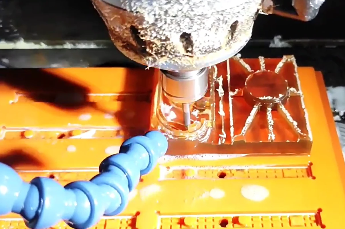
Coolant and chip evacuation. Air blast or vacuum chip removal is often useful because recutting hot chips can mark the surface. Many PEI operations can be machined dry, but drilling, parting, close-tolerance work or surface-finish control may benefit from a compatible non-aromatic water-soluble coolant. Avoid assuming that a metalworking oil is automatically safe for an amorphous PEI part; chemical compatibility, stress-cracking risk and downstream cleanliness must be reviewed.
Moisture: Pellet Drying Is Not the Same as CNC Stock Conditioning
Moisture control is often confused because resin pellets and CNC stock shapes enter manufacturing through different routes. Resin pellets intended for injection molding or extrusion may have a supplier-defined pre-drying schedule to prevent molding defects. That pellet-drying schedule should not be copied automatically into a CNC traveler for finished PEI sheet, rod or block.
For machining stock, the more relevant question is dimensional conditioning. If a drawing contains tight fits, flatness controls or dimensions sensitive to temperature and humidity, the stock and finished part should be allowed to stabilize in a controlled inspection environment before final measurement. The exact conditioning time depends on part mass, wall thickness, storage history and the stock-shape supplier’s instructions. Record ambient temperature and, when it matters, humidity at final inspection. The objective is traceable measurement stability, not a ritual drying cycle applied to every PEI blank.
Does ULTEM Machining Require Post-Curing?
‘Post-curing’ is not the correct blanket term for CNC-machined ULTEM. PEI is a thermoplastic; the material does not require a cure reaction after cutting. What may be useful on selected precision parts is stress-relief annealing. That is a thermal conditioning operation intended to reduce machining or stock residual stress, not to ‘cure’ the polymer.
Intermediate or post-machining annealing is most relevant when a part combines heavy material removal with demanding flatness, thin walls, deep pockets, or very tight feature-to-feature control. One supplier’s PEI stock-shape guide, for example, shows a PEI annealing cycle around 200 C with controlled heat-up, soak and slow cooling. That example is not a universal ULTEM instruction. The appropriate cycle must come from the actual stock-shape supplier and must remain below limits that would cause unwanted dimensional change, oxidation, fixture imprint or surface degradation. In many ordinary ULTEM machining jobs, no secondary anneal is required at all.
A risk-controlled process therefore reads: review the stock condition and geometry first; rough machine if necessary; allow the part to normalize; use supplier-approved stress relief only when engineering evidence justifies it; then finish machine and inspect. This avoids the false claim that every ULTEM machining project must receive the same post-process heat treatment.
Anonymized ULTEM 1000 Machining Case: Small Precision Hole Pattern
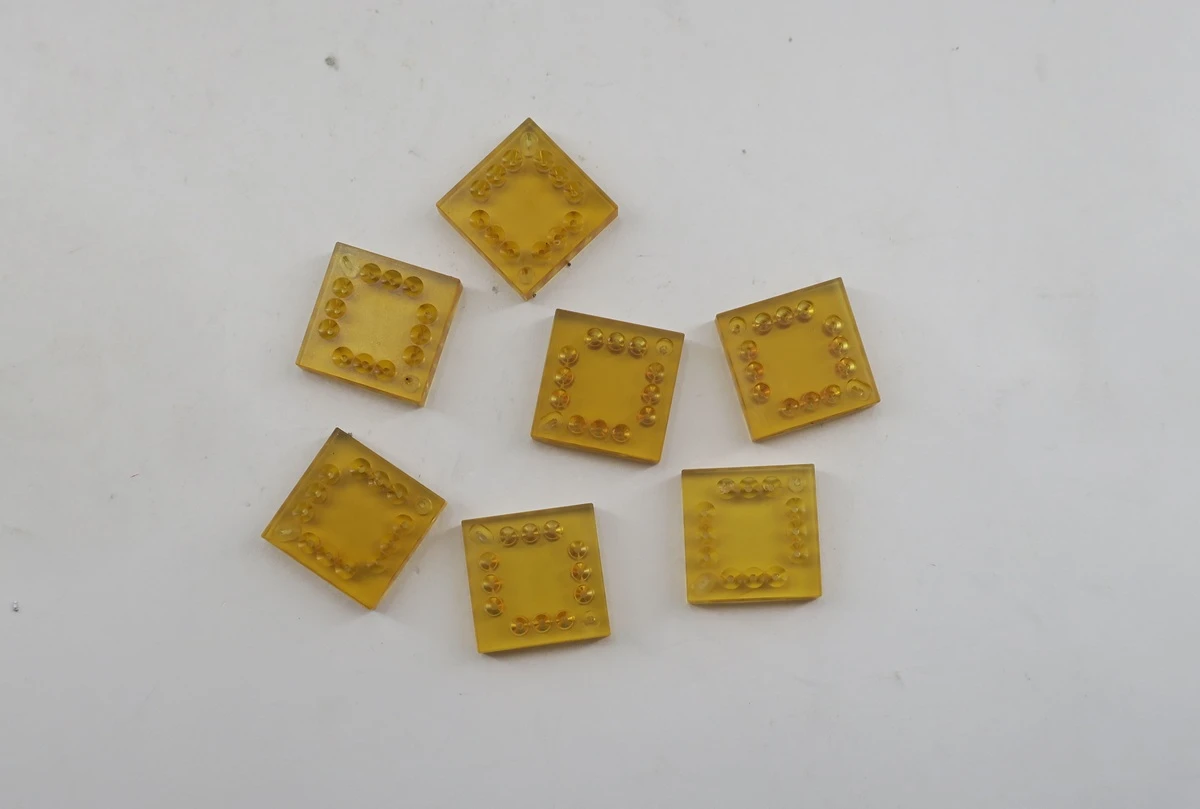
A useful example of drawing-driven ULTEM machining is an anonymized ULTEM 1000 component from a recent project. The source drawing identifies the material as ULTEM 1000 (PEI) and shows a nominal 15.00 x 15.00 mm body with 3.18 mm thickness and a repeated twelve-hole pattern. The drawing also requires the finished part to be free of oil and visually detectable contaminants, uses model-based controls for unspecified geometry, and specifies edge requirements. These details are more important than a website-wide promise such as ‘all ULTEM parts are +/-0.02 mm.’
For this type of part, the machining route should be designed around the actual hole size, positional control, thickness, datum scheme and inspection method. Dense drilling on a small amber PEI plate can accumulate heat rapidly, so chip evacuation, sharp drills and consistent support matter. Final inspection should be tied directly to the released drawing and finished condition. If the design changes from unfilled ULTEM 1000 to a glass-filled grade, tooling, wear monitoring and possibly the allowance strategy should be reassessed rather than copied unchanged.
Inspection and Quality Control for ULTEM Machined Parts
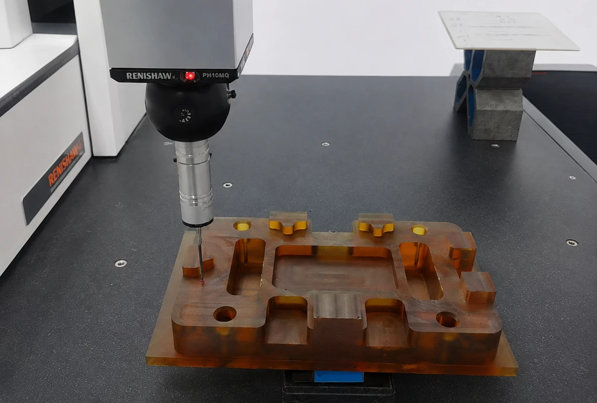
Inspection of ULTEM machined parts should reflect both the drawing and the behavior of engineering plastics. A CMM can be appropriate for location, profile and datum-related measurements, but low contact force and a stable fixture are important when the component is thin or flexible. Optical measurement, vision systems, pin gauges, thread gauges, micrometers and height instruments may be better for specific features. The inspection plan should choose the method that generates the least measurement-induced deformation while still satisfying the drawing.
A practical final inspection plan may include material/lot verification, visual cleanliness, overall dimensions, critical hole diameters and positions, flatness or profile, threads or inserts, surface roughness where specified, and a first-article report when the customer requires one. Dimensional results should be recorded after the part has reached the agreed inspection environment. For multi-operation parts, an in-process check after roughing or after a key datum is established can catch stress movement before expensive finishing is completed.
No universal tolerance should be advertised for ULTEM machining. Achievable tolerance is feature-specific and depends on part size, wall thickness, grade, stock form, residual stress, fixture strategy, thermal environment and measurement uncertainty. The defensible commercial statement is that critical tolerances are reviewed against the 2D drawing and quoted by feature.
Medical, Aerospace and Photonics Compliance: What You Can and Cannot Claim
ULTEM machining appears in demanding industries because PEI combines properties that ordinary plastics may not deliver at the same time. In medical equipment, machined PEI can be used for housings, fixtures, handles, insulating components and other non-implant hardware where temperature resistance and dimensional stability are useful. However, ‘medical grade,’ biocompatibility, sterilization compatibility and regulatory status are grade- and application-specific. A generic ULTEM 1000 part should not be marketed as ISO 10993 or USP Class VI compliant unless the exact healthcare grade, supplier documentation and finished-device requirements support that statement.
In aerospace and transportation, ULTEM grades are used where low weight, electrical insulation and flame/smoke behavior are important. Here again, UL94 or aircraft FST performance is tied to the exact resin grade, color, thickness and test standard. Machining a PEI blank does not automatically make the finished component compliant with every aerospace fire requirement. The purchase order should identify the required material certificate and any downstream conformity evidence.
Photonics, semiconductor and scientific-instrument projects may use PEI for insulating mounts, detector housings, sensor fixtures, cable interfaces and lightweight structural pieces. If a design relies on optical transmission or low outgassing, use the exact material data for the specified grade and thickness; do not infer optical performance from the natural amber appearance. For FDA food-contact or fluid-path work, confirm the exact formulation, color, stock-shape traceability and applicable end-use regulation rather than publishing the blanket phrase ‘ULTEM is FDA approved.’
DFM Checklist for Precision ULTEM Plastic Machining
Good DFM for ULTEM starts by identifying what must be precise and what merely needs clearance. Tighten tolerances only on features that control fit, sealing, alignment or function. This reduces cycle time and the amount of material that must be removed after the part has reached a stable state.
Avoid zero-radius internal corners and abrupt wall-thickness changes where possible. Add internal radii that permit a robust cutter and reduce stress concentration. Support thin walls during machining, and consider sacrificial tabs or soft jaws when clamping faces would otherwise distort. For deep holes, provide drill access and chip-clearance strategy. For inserts, define the insert specification, installation method and pull-out/torque requirement rather than simply calling out a threaded hole in plastic.
For glass-filled grades, indicate which surfaces are cosmetic or sealing-critical so the supplier can plan tool-life control and finishing. On large flat parts, specify flatness in the actual functional state and, if relevant, inspection temperature. On all regulated work, place material and compliance requirements on the drawing or purchase specification rather than relying on the material family name.
- Specify the exact ULTEM/PEI grade and stock form on the drawing or PO.
- Identify critical dimensions, datums, fits, flatness and inspection conditions instead of over-tolerancing every feature.
- Use internal radii and balanced wall thickness where function allows; support thin walls during cutting.
- Plan deep and micro-hole chip evacuation, breakthrough support and inspection method before machining.
- Separate roughing from finish machining on parts with heavy material removal or distortion risk.
- Define insert type, installation process and functional torque/pull-out requirement when metal inserts are used.
- For reinforced grades, plan tool-wear checks and define cosmetic/sealing-critical surfaces.
- Put compliance and material-certificate requirements on controlled purchasing documents, not only in website prose.
FAQ: ULTEM Machining
Is ULTEM easy to machine?
Yes, especially unfilled ULTEM 1000, but it still requires sharp tooling, chip evacuation, controlled heat and sensible workholding. Glass-filled ULTEM 2300 and 2400 are more abrasive and normally demand tighter tool-wear control.
What is the difference between ULTEM 1000 and ULTEM 2300 for CNC machining?
ULTEM 1000 is unfilled and generally easier to finish cleanly. ULTEM 2300 contains 30% glass fiber, increasing stiffness and dimensional stability under load but also increasing abrasiveness and the risk of breakout at sensitive features.
Do all ULTEM machined parts need post-curing or annealing?
No. PEI is a thermoplastic and does not require a generic post-cure. Stress-relief annealing is optional and project-specific. Use it only when geometry, stock condition or tolerance stability justifies it and follow the stock-shape supplier’s approved cycle.
Can ULTEM be machined dry?
Many operations can be performed dry with air blast or vacuum chip removal. For drilling, parting, close tolerances or surface-finish control, a compatible non-aromatic water-soluble coolant may be useful. Coolant compatibility and downstream cleanliness requirements must be checked.
What tolerance can ULTEM machining hold?
There is no honest single number for every part. Capability depends on grade, feature size, wall thickness, stock condition, toolpath, fixture, temperature and measurement method. Critical dimensions should be reviewed and quoted from the drawing feature by feature.
Does ULTEM absorb moisture?
PEI has relatively low moisture uptake compared with many engineering plastics, but precision dimensions can still be affected by environment. Do not confuse resin-pellet drying instructions with CNC stock conditioning; stabilize machined parts before close-tolerance inspection when required.
Is ULTEM FDA approved or biocompatible?
Not as a blanket material-family claim. Some specific grades and colors have regulatory or healthcare documentation. Confirm the exact resin/stock grade, supplier declaration, lot traceability, sterilization method and finished-device requirements before making FDA, ISO 10993 or USP Class VI claims.
ULTEM vs PEEK: which is better for CNC parts?
Neither is universally better. ULTEM can be attractive when electrical insulation, flame behavior, dimensional stability and cost balance are priorities. PEEK is often preferred for more severe chemical, wear or temperature environments. Select from the actual load, temperature, chemical exposure, compliance and cost requirements.
RFQ: Send Your ULTEM Machining Project for Engineering Review
| RFQ information that shortens engineering review
Send Rollyu Precision your STEP/3D model and 2D drawing together with the exact ULTEM or PEI grade, stock form, quantity, critical tolerances, surface requirements, operating temperature, chemical exposure, cleanliness/compliance documents and inspection-report requirements. Our engineering review can then confirm manufacturability, identify high-risk features, recommend a machining/inspection route, and quote the project without relying on generic tolerance or process assumptions. |
