
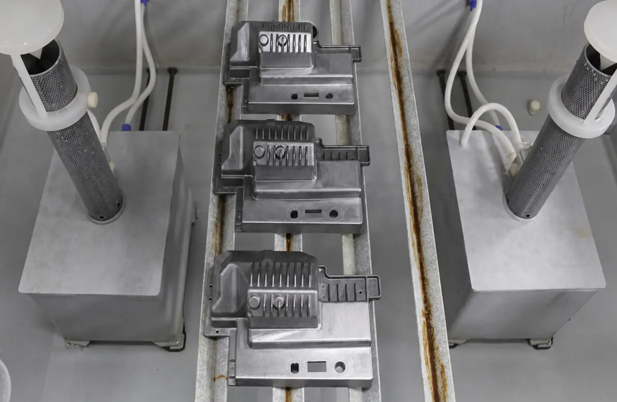

Metal injection molding (MIM) usually fits small, feature-dense, high-volume parts when a qualified MIM material system meets the design requirements. In this article, die casting means high-pressure die casting of aluminum or zinc alloys. High-pressure die casting usually fits larger thin-wall housings, covers, brackets, and frames.
Annual volume does not decide the process on its own. Material requirements, feature geometry, dimensional risk, secondary machining, and the cost of a design change determine the better finished-part route.
What Are the Main Differences Between MIM and Die Casting?
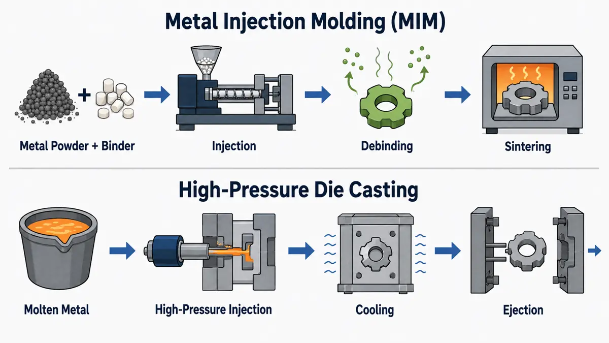
MIM shapes metal powder mixed with binder, then removes the binder and sinters the part. High-pressure die casting injects molten aluminum or zinc into a steel die. These routes create different material limits, dimensional risks, and inspection needs.
| Decision factor | MIM | High-pressure die casting |
|---|---|---|
| Starting material | Fine metal powder and polymer binder | Molten aluminum or zinc alloy |
| Shape-forming stage | Injection molding creates a green part | Pressurized molten metal fills a steel die |
| Final consolidation | Debinding and sintering bond the metal powder | Metal solidifies in the die |
| Typical design fit | Small parts with dense features | Larger thin-wall housings, covers, brackets, and frames |
| Main process risk | Sintering shrinkage and density variation | Porosity, fill defects, and distortion |
| Common follow-on work | Sizing, machining, heat treatment, or finishing | Trimming, machining, finishing, and inspection |
Feedstock and Forming Methods
MIM feedstock combines fine metal powder with a polymer binder. The injection mold forms an oversized green part. Debinding removes most of the binder, and sintering bonds the powder into a dense metal component.
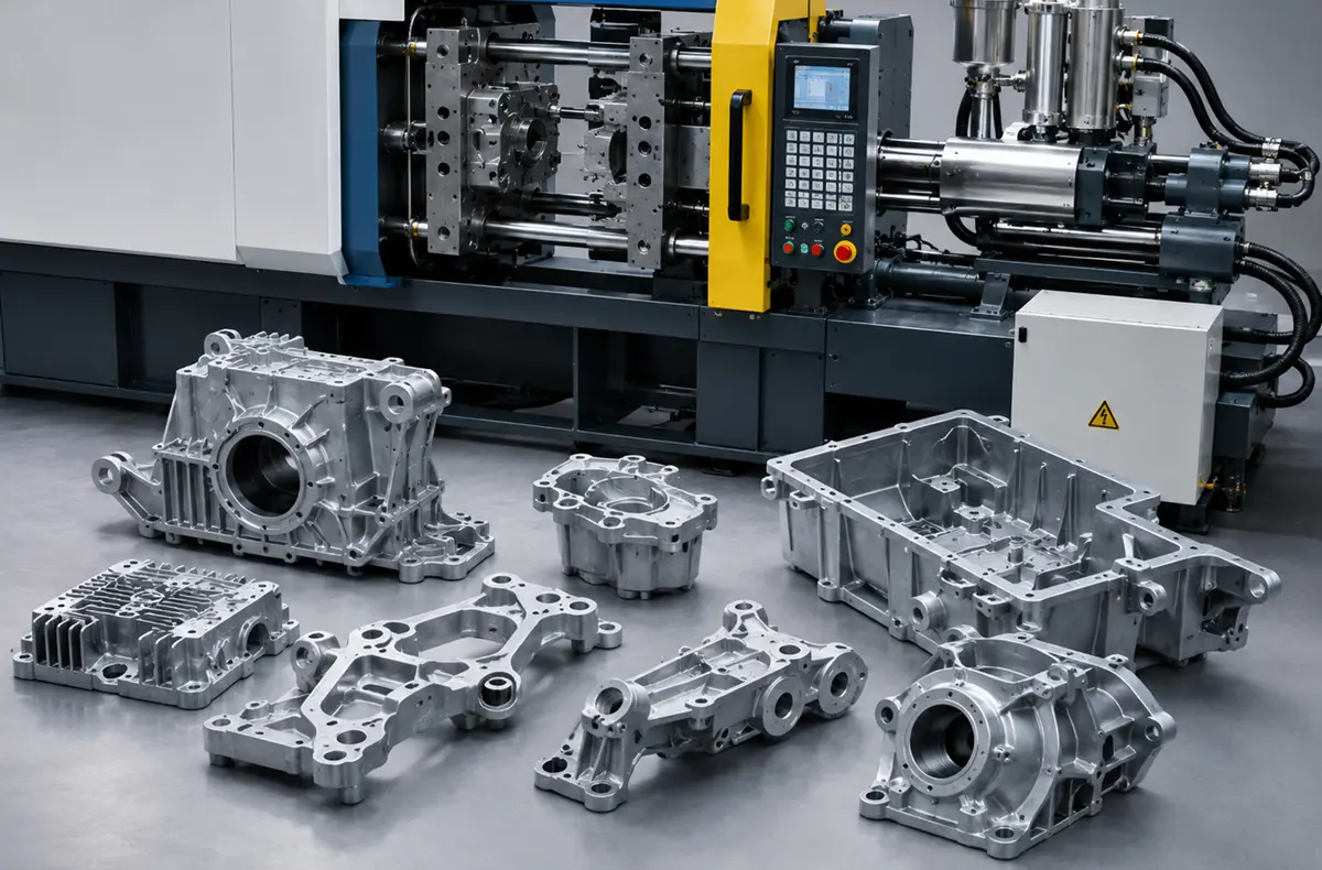
High-pressure die casting melts an aluminum or zinc alloy and injects it into a steel die. The casting solidifies before ejection, then moves to trimming, machining, finishing, or inspection as required. A high-pressure die-casting process forms and consolidates the part in the die, so it does not use the separate debinding and sintering stages required by MIM.
Material Compatibility
Material choice can remove one option before geometry or volume becomes relevant. MIM commonly uses qualified stainless steel and low-alloy steel feedstock systems, but the supplier must confirm the alloy, sintered density, heat treatment, and test data for the application.
High-pressure die casting is relevant when the part can use a cast aluminum or zinc alloy. If the drawing requires a specific wrought condition, unusual chemistry, high-temperature performance, or specialized joining behavior, compare MIM with CNC machining, investment casting, or another qualified route. State the exact material specification and required properties on the drawing instead of naming only a broad material family.
Dimensional Changes During Production
MIM shrinks during sintering. The tool cavity must account for the supplier’s feedstock, furnace cycle, loading method, and part geometry. A shrink factor from a similar part can guide development, but production-intent samples must prove the final dimensional capability.
High-pressure die castings contract as the metal cools. Die temperature, fill conditions, wall thickness, and ejection affect the result. Critical bores, sealing faces, and threads often need machining stock. The casting tool, machining fixture, and finished drawing should also share one datum scheme because a datum change between operations can shift the finished feature.
Which Part Designs Favor MIM or Die Casting?
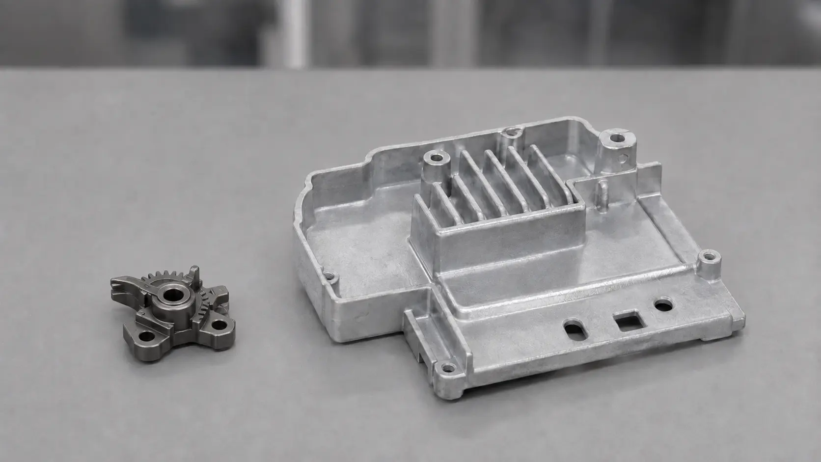
MIM usually favors compact components with dense geometry. High-pressure die casting usually favors aluminum or zinc parts with a larger footprint and thin walls. Material, tolerance, cosmetic requirements, and tool complexity can still change the choice.
Small, Feature-Dense Components
MIM can suit small parts with repeated external features, fine profiles, and shapes that would otherwise need multiple machining setups. Combining suitable features in one molded part can reduce handling and machining after sintering.
The geometry must release from the molding tool and remain stable through sintering. Deep blind features, sharp internal corners, unsupported thin sections, and small holes need early review. Before tooling approval, mark each feature as molded, machined, or redesigned and assess it in the finished condition rather than only on the green part.
Thin-Wall Housings and Larger Parts
High-pressure die casting often suits aluminum or zinc housings, covers, brackets, and frames with thin walls across a larger area. The die must support metal flow, venting, ejection, and cosmetic requirements. Heavy bosses beside thin walls need particular attention because uneven cooling can increase local shrinkage, distortion, or porosity. Review these transitions before die design begins, even when the CAD model appears easy to cast.
Undercuts, Internal Features, and Machining Access
Undercuts and internal features affect tool cost, cycle time, maintenance, and inspection access in both processes. A casting versus machining comparison should therefore use the finished feature cost rather than the raw-shape price.
- Use a slide, lifter, core, or other tool action when the production volume offsets the added tooling and maintenance.
- Machine the feature when the tool action would be unstable, difficult to inspect, or likely to restrict ejection.
- Redesign the feature when neither route can hold the required geometry at an acceptable finished-part cost.
This decision matters most for tight bores, sealing faces, critical threads, and internal passages. A low-cost molded or cast feature can become expensive when it needs dedicated fixturing or inspection.
What Quality Risks Affect MIM and Die-Cast Parts?
MIM quality planning must control sintering variation. Die-casting quality planning must control fill behavior and internal soundness. Each inspection method should address a defined functional risk.
Sintering Shrinkage and Dimensional Stability
Sintering shrinkage does not prevent MIM from producing precise parts, but it makes process control essential. Feedstock consistency, molding conditions, furnace atmosphere, thermal cycle, part loading, and section thickness can change the final dimensions.
Define functional datums, measurement methods, and sampling requirements before the toolmaker cuts steel. First-article samples should use production-intent feedstock and furnace conditions. A trial made with a different material batch or furnace route does not demonstrate final production capability, so the approval record should identify the conditions used.
Casting Porosity and Pressure Integrity
High-pressure die casting needs a pressure-integrity review when a part contains fluid, gas, or vacuum. Entrapped gas, shrinkage, and fill conditions can create internal voids that visual inspection and CMM measurement cannot detect. Define leak testing, radiography, CT scanning, sectioning, or another agreed method according to the failure risk. Machining depth also matters because cutting a sealing face, bore, or thread can expose subsurface porosity.
Parting Lines, Ejector Marks, and Machining Allowances
Parting lines, gate remnants, and ejector marks should stay away from sealing faces, visible surfaces, locating datums, and mating interfaces. Mark cosmetic and functional zones on the drawing so the toolmaker can place these features where they do not affect assembly or appearance.
Add machining allowance only where the finished feature needs it. Too little stock can leave an as-cast surface on a critical feature, while excess stock adds machining time and may expose porosity. The raw casting, machining fixture, and final drawing need the same datum references.
Critical Tolerances and Inspection Planning
Match the inspection method to the characteristic instead of assigning CMM inspection to every requirement.
- Use CMM inspection or functional gauges for accessible dimensions, positions, and mating features.
- Use leak testing, radiography, CT scanning, or sectioning when function depends on internal soundness.
- Define containment, re-inspection, and process-review triggers for characteristics that trend toward a limit.
A production-intent first article inspection should record the drawing revision, material lot, process route, measured features, and agreed test results. This record establishes the approved baseline before production ramps.
How Should OEMs Make the Final Process Decision?
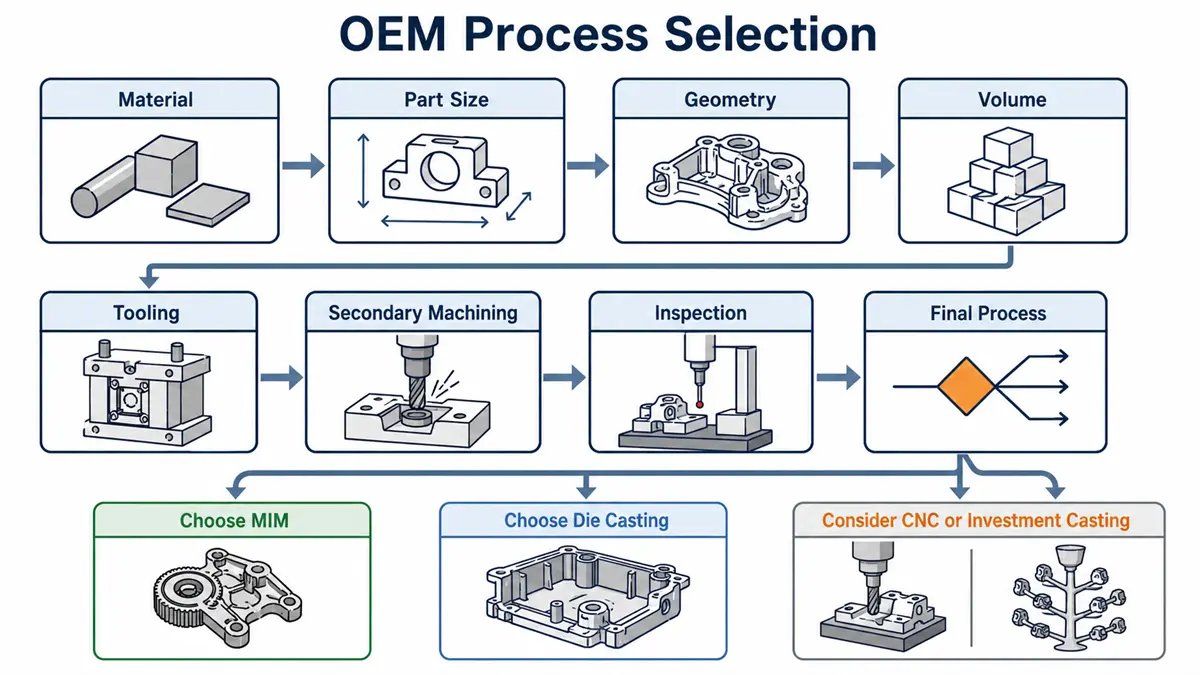
OEMs should compare the finished part rather than the raw molding or casting price. Tooling, yield, secondary work, inspection, documentation, and design-change exposure all affect total program cost.
Tooling Investment and Design Changes
MIM and high-pressure die casting both need specialized production tooling. MIM tooling must account for molding, debinding, and sintering behavior. Die-casting tooling must control fill, venting, solidification, ejection, and trimming.
Review likely engineering changes before the toolmaker cuts steel. A minor CAD revision can require a new core, slide, cavity insert, machining fixture, or inspection gauge. If the design is still moving, compare a temporary manufacturing route with the cost and lead time of modifying production tooling after validation.
Break-Even Volume and Total Part Cost
No fixed break-even volume applies to MIM and high-pressure die casting. Calculate the crossover with the same finished-part scope for each process:
- Separate tooling and nonrecurring engineering from the recurring unit price.
- Compare low, expected, and high demand across the planned program life.
- Include material, cycle time, yield, secondary machining, finishing, inspection, maintenance, and scrap exposure.
- Use the same acceptance criteria, documentation, packaging, and delivery condition in both quotes.
A lower raw-part price does not prove a lower total cost when one route needs more machining, testing, or fixture control.
Secondary Machining and Finishing Requirements
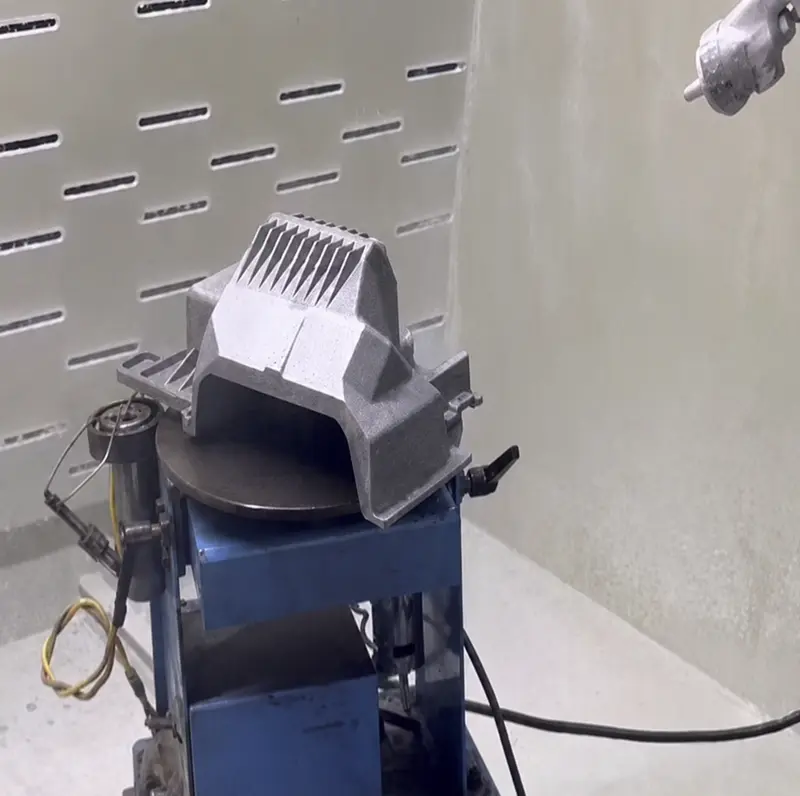
Secondary work can determine the better process when a part needs tight bores, threads, sealing faces, flat mounting pads, or a controlled surface finish. MIM may need sizing, machining, heat treatment, or finishing after sintering. Die castings often need trimming and CNC machining before critical features are ready for assembly.
For aluminum or zinc die-casting parts, Rollyu Precision lists high-pressure casting, deburring, secondary CNC machining, finishing, and inspection. The RFQ should identify every as-cast surface and every machined, masked, coated, or measured feature. This gives the supplier one defined delivery condition for pricing.
Quote-Ready Drawings and Cost Comparison
A quote-ready package defines the finished part and the evidence required for acceptance. Give each supplier the same controlled inputs:
- A 3D model and 2D drawing with revision control, datums, GD&T, and critical dimensions
- Annual demand, program life, prototype quantity, and production ramp
- The exact material specification, target properties, and heat-treatment requirement
- Pressure, sealing, joining, cosmetic, surface-finish, and assembly requirements
- Secondary machining, finishing, packaging, and inspection requirements
- Material certification, Certificate of Conformance, dimensional reports, and first-article documentation
Before tooling release, confirm whether Rollyu Precision or another supplier has priced the same finished condition, inspection scope, and change-control terms. Quotes that cover different delivery states cannot support a valid process comparison.
FAQs
Are MIM parts as strong as machined or wrought metal parts?
A qualified MIM material system can meet demanding strength requirements. Final properties depend on the feedstock, sintered density, heat treatment, and process control. Do not treat MIM as interchangeable with a wrought or machined alloy until the supplier provides test data for the required service condition.
Can MIM and die-cast parts be heat treated?
Some MIM materials and die-cast alloys can be heat treated. MIM heat treatment must follow the qualified material system. Conventional high-pressure die castings need a review of alloy chemistry, trapped gas, porosity, distortion, and the thermal cycle. High-integrity die-casting variants require a separate process review.
Can MIM and die-cast parts be welded or joined to other components?
Manufacturers can join MIM and die-cast parts after qualifying the method for the alloy, density, wall thickness, surface condition, and service load. Welding heat can distort thin sections or expose casting defects. Mechanical fastening, brazing, adhesive bonding, press fits, or integrated assembly features may be more suitable when welding threatens part function.
What material certificates and inspection records should buyers request?
Request raw-material certification or a material test report when it is available for the feedstock or casting-alloy lot. A Certificate of Conformance should identify the drawing revision and delivered condition. Add dimensional reports, first-article records, and agreed leak, density, hardness, cosmetic, or functional results when those characteristics affect acceptance.
When is investment casting a better alternative to MIM or die casting?
Investment casting may fit a part that is too large for MIM or needs a castable alloy outside the high-pressure die-casting route. It can also suit demand that does not justify die-casting tooling. Confirm the attainable tolerance, surface condition, internal-quality risk, and machining allowance before choosing it.
