

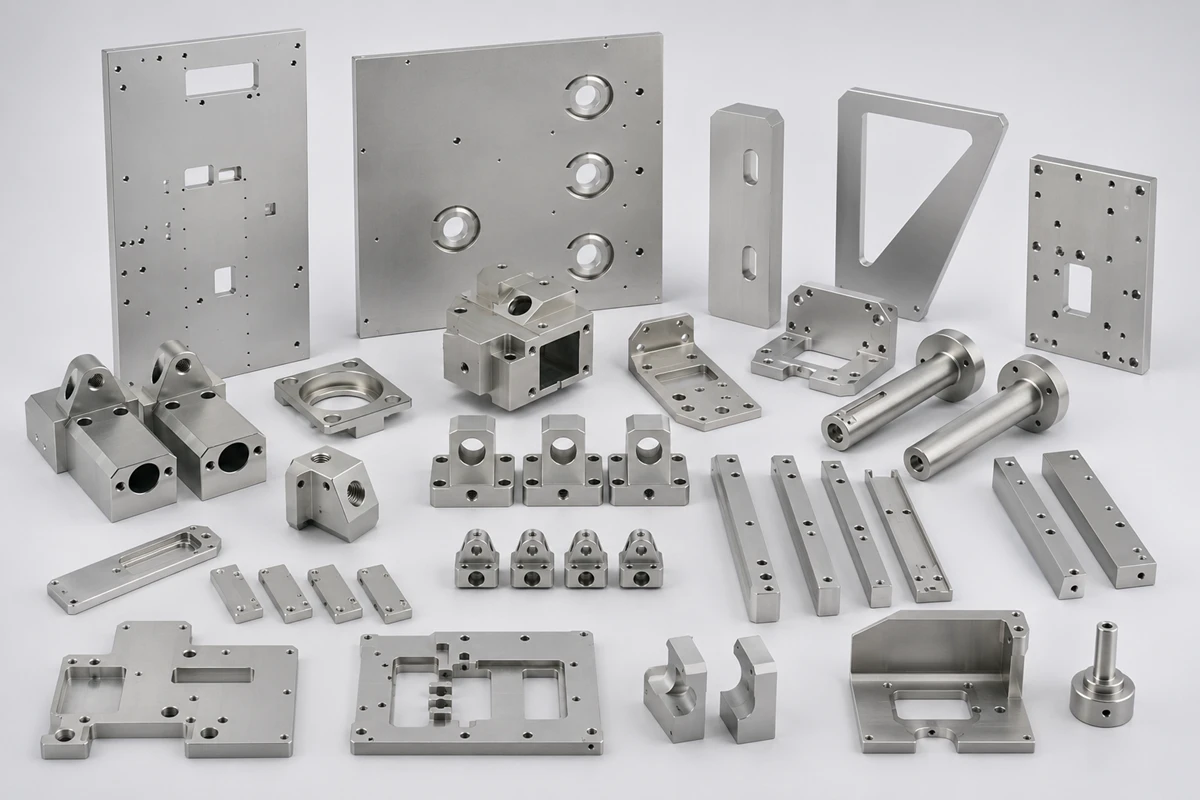
Clear anodize is often written on a drawing as if it were only a color choice. In precision CNC work, it is a dimensional, electrical, cosmetic, and supply-chain decision at the same time. A part can pass machining inspection and still fail at assembly after anodizing if a bearing bore closes up, a ground contact becomes insulated, a thread fit changes, or a supposedly “silver” batch looks different from the previous lot.
For procurement engineers and mechanical engineers, the useful question is not simply “Can this part be clear anodized?” It is: which alloy, anodize type, coating requirement, masking plan, pre-finish, inspection method, and drawing callout will produce a repeatable part without creating hidden assembly risk? This guide focuses on custom clear anodized aluminum parts produced by CNC machining, including Type II clear anodize, non-dyed or natural anodizing, and clear hard anodizing where Type III is truly required.
What Are Clear Anodized Machining Parts?
Clear anodized machining parts are CNC-machined aluminum components finished with a non-dyed anodic oxide coating. Most buyers mean Type II Class 1 when they want corrosion protection and a natural metallic appearance; Type III Class 1 is a harder, usually thicker wear coating and may look gray, bronze, olive, or darker rather than bright silver. Before RFQ, define the alloy/temper, governing specification, Type and Class, masking, critical dimensions after finish, thread requirements, cosmetic sample, sealing, marking, and inspection evidence. “Clear,” “natural,” and “silver anodized” describe search language or appearance; they are not complete engineering callouts by themselves.
Need a drawing review before quotation? Send your 3D CAD, 2D drawing, alloy/temper, quantity, finish callout, critical fits, and cosmetic surfaces. Rollyu Precision can flag machining-to-anodize risks such as masking, post-finish dimensions, threaded features, and laser marking before the RFQ moves into production.
Clear Anodizing, Natural Anodizing, Silver Anodized: What Buyers Actually Mean
The market uses several phrases for similar-looking finishes: clear anodizing, natural anodizing, non-dyed anodizing, clear anodized aluminum, and sometimes silver anodized. They should not be treated as perfectly interchangeable technical specifications.
“Clear” describes the absence of intentional dye, not a water-clear coating. The anodic oxide is integrated with the aluminum surface, and the final appearance still depends on alloy chemistry, temper, machining marks, pretreatment, coating thickness, sealing, and viewing conditions. A natural anodized 6061 part may appear silver-gray; a high-copper or high-zinc alloy can look noticeably darker. A Type III Class 1 hardcoat may be gray, bronze, olive, or dark rather than visually “clear.”
“Silver anodized” is especially risky on drawings because it can describe an appearance rather than a controlled process. In some supply chains it means clear/natural anodize over a bright or satin aluminum surface. In others it is simply a buyer’s visual description. If interchangeability matters, specify the anodize type and class, then define cosmetic acceptance separately instead of relying on the word silver.
Direct answer: Clear anodized vs silver anodized — are they the same?
Not necessarily. They may look similar and are sometimes used as direct replacement terms in purchasing language, but “silver anodized” is not a sufficiently controlled process definition by itself. For engineered parts, use a specification such as non-dyed Type II Class 1 plus an approved appearance standard or sample when color and gloss matter.
Type II Clear Anodize vs Clear Hard Anodizing (Type III)
Two requests are commonly mixed together: conventional clear anodize and clear hard anodize. Under MIL-PRF-8625 terminology, Type II is conventional sulfuric acid anodizing and Type III is hard anodic coating. Class 1 means non-dyed; Class 2 means dyed. The correct choice should be driven by function, not by the word “clear.”
| Decision point | Type II, Class 1 | Type III, Class 1 | Main design risk | Procurement guidance |
| Typical intent | Corrosion protection, general durability, natural metallic appearance | Wear/abrasion resistance and a harder anodic layer | Choosing hardcoat only for appearance can add dimensional and color risk | Use Type III only when functional wear or coating requirements justify it |
| Appearance | Usually light silver/gray but alloy dependent | Often darker gray/bronze/olive; “clear” does not mean transparent | Batch-to-batch or alloy-to-alloy color mismatch | Control alloy, pretreatment, processor, and approved sample if cosmetic |
| Dimensional effect | Can matter on tight bores, threads, pins and locating surfaces | Usually more significant because hardcoat is commonly thicker | Post-finish fit changes | State critical dimensions after finish and define masking |
| Sealing | Commonly sealed when corrosion performance is required | Seal choice depends on drawing and wear/corrosion priorities | Assuming all seals are equivalent | Follow the governing specification and application requirement |
| Best fit | Housings, brackets, panels, carriers, enclosures, motion hardware | Wear surfaces, sliding interfaces, selected high-abrasion components | Over-specification | Match coating to the failure mode, not to a generic finish preference |
MIL-A-8625 vs MIL-PRF-8625: do not silently substitute a legacy callout
Many legacy drawings and ERP records still use MIL-A-8625 or shortened forms such as “MIL-8625-F.” As of August 2026, U.S. DoD QuickSearch lists MIL-PRF-8625F with Amendment 2 (23 Nov 2020) as the active performance specification for anodic coatings on aluminum and aluminum alloy. If a controlled customer drawing says MIL-A-8625, do not unilaterally rewrite the requirement; clarify whether the customer expects the legacy callout, the current performance specification, or an approved equivalent. This is both a technical and contract-control issue.
Alloy Selection: Why 6061, 7075, 2024, 5052 and Tooling Plate Do Not Look the Same
The phrase clear anodized aluminum can create the false expectation that all alloys will finish with the same “silver” color. They will not. Alloying elements change the way the substrate reacts during pretreatment and anodizing. For cosmetic assemblies, material selection is therefore part of finish control.
| Alloy / product form | Why it is selected | Clear-anodize appearance tendency | Design / sourcing note |
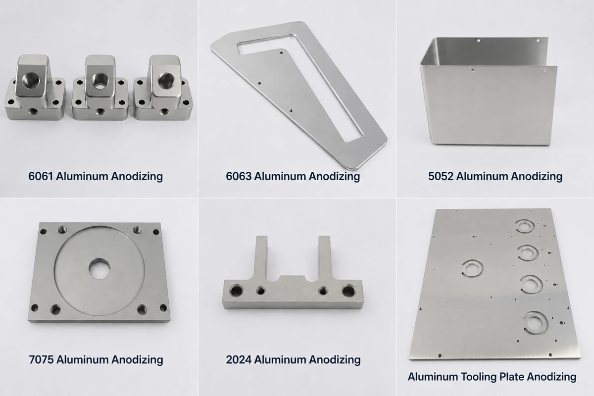
| 6061-T6 / 6082 | General precision CNC parts; strong balance of machinability, strength, availability | Often a relatively predictable natural silver/gray finish | Good baseline for mixed functional and cosmetic requirements, but approve a sample for strict color matching |
| 6063 | Extrusions and cosmetic profiles | Can produce an attractive light natural finish with controlled pretreatment | Useful for clear anodized extrusions; machining and extrusion surface history can still create variation |
| 5052 | Sheet metal, covers, panels, formed components | Often visually uniform when material and pretreatment are consistent | Useful for clear anodized panels/enclosures; forming marks remain visible unless addressed |
| 2024 | Higher strength, aerospace-type applications | May appear grayer or less uniform because of copper content | Do not select for “bright silver” appearance without samples and qualification |
| 7075 | High-strength structural parts | Can shift darker/gray, especially with thicker anodic coatings | Functional requirements should take priority over cosmetic color expectations |
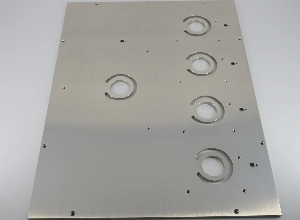
| Cast/tooling plate | Large plates, fixtures, machine bases | Mottling or local color variation can occur because of cast microstructure | For large cosmetic faces, define visual acceptance or use an approved master sample |
Tolerance and Masking: The Point Where Machining and Anodizing Must Be Designed Together
An anodic coating is not an independent paint film that simply sits on top of an unchanged part. Aluminum is converted to oxide and some coating growth occurs outward from the original surface. The exact dimensional change depends on process, alloy, thickness, geometry and measurement method. For that reason, a universal “add X microns per side” rule is not safe for every drawing.
Critical bores, bearing fits, pins and sliding interfaces
Bearing bores, dowel holes, shaft fits, precision slots, linear-guide seats and valve interfaces should be reviewed before the machining dimensions are frozen. The drawing should state whether the final dimension applies before or after anodizing. If the interface must remain metallic or cannot tolerate coating build, use masking or a qualified post-finish operation. If the anodic surface is functional, machine the pre-anodize feature to the approved compensation strategy and verify the dimension after finishing.
Threads and fastener interfaces
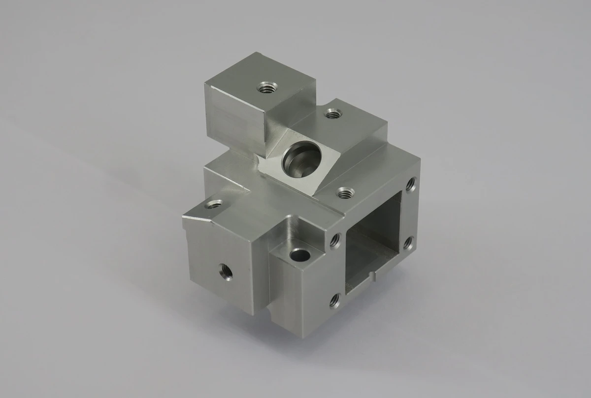
Anodize on internal and external threads can change fit and increase friction. There is no universal rule that every thread must be masked: noncritical threads may be processed successfully, while fine-pitch, class-of-fit, sealing, repeated-assembly, or electrically bonded threads may require masking or dimensional allowance. Put the decision on the drawing rather than leaving it to shop-floor interpretation.
Masking is a functional requirement, not just a cosmetic note
Common masking targets include ground/bonding pads, precision datums, bearing seats, electrical contact surfaces, press-fit holes, selected threads, sealing lands, and areas intended for subsequent welding or conductive assembly. A reliable RFQ should identify these areas in the 2D drawing or with a clearly keyed masking map. Text-only notes such as “mask critical areas” create unnecessary supplier ambiguity.
Electrical Insulation, Grounding and EMI: What Clear Anodize Changes
The anodic aluminum oxide layer is electrically insulating. That can be beneficial when isolation is required, but it can be a failure mode when a chassis, sensor, shield, motor frame, or stage relies on metal-to-metal electrical bonding. The bulk aluminum component may contribute to electromagnetic shielding, yet an anodized interface should not be assumed to provide a low-resistance bond through the coating.
If grounding matters, identify conductive contact pads and fastener interfaces that must remain free of anodize or be treated with an approved conductive interface. Do not claim a specific dielectric strength from the finish name alone. Electrical breakdown depends on coating thickness, porosity, sealing, edge condition, humidity, test method and geometry; validate it when it is a design requirement.
Appearance Control: Color Variation, Sandblasting, Metallic Texture and Laser Marking
Clear anodize is popular because it preserves a metallic appearance without an intentional dye. That does not mean it hides the machining history. Tool paths, blended edges, polishing marks, bead-blast texture, weld heat tint, extrusion lines and local hand finishing can remain visible or become more noticeable after anodizing.
For a sandblasted clear anodized or bead-blasted clear anodized finish, the blast step should be treated as a controlled pretreatment. Media type, pressure, distance, time and masking affect texture and edge definition. Precision datums and sealing surfaces should normally be protected from unnecessary blasting. If a part must match an existing production family, use a finish sample rather than relying on a verbal “matte silver” description.
Color variation should be expected across different alloys, heat lots, thicknesses, surface textures, sealing conditions, processors and batch loads. Even parts made from the same nominal alloy can show slight shade differences. If visual consistency is critical, define the viewing standard, acceptable range, lot matching requirement, and master sample. Do not write an absolute promise such as “exact silver color every batch.”
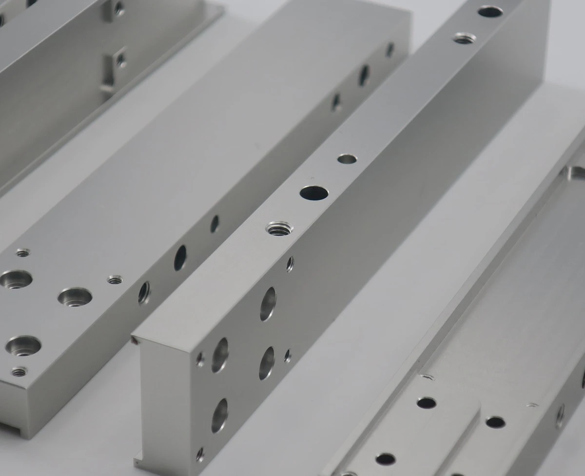
Laser marking on clear anodized aluminum
Laser marking can be used for serial numbers, orientation marks, identifiers and traceability after anodizing, but contrast is process dependent. Clear Type II does not behave like a black dyed coating, so a “white mark on black” result should not be assumed. The laser can modify the anodic layer and underlying surface to create a gray, dark, light, or etched appearance depending on wavelength and parameters. For cosmetic or machine-vision requirements, approve a test coupon or first article.
Application Decisions by Industry: Pain Point, Design Risk and Finish Choice
A useful finish specification connects the coating to the assembly failure mode. The same clear anodized surface can be correct in one industry and problematic in another if optical, electrical, fit, cleaning, vacuum or wear requirements are ignored.
Photonics: optical mounts, filter carriers, mirror supports and instrument frames
Primary pain point: mechanical stability and clean metallic appearance without accidentally compromising optical behavior. Clear anodize can be appropriate for structural mounts, carriers and covers, but it has no fixed optical reflectance. Reflectance depends on alloy, surface texture, thickness, wavelength and angle. If stray-light suppression is critical, a black anodized or specialized optical-black solution may be more suitable. Protect precision datums, optical reference surfaces and any required grounding interfaces.
Quantum: sensor hardware, precision frames and positioning structures
Primary pain point: mixed mechanical, electrical and environmental requirements. A non-dyed anodic layer can provide corrosion protection and electrical isolation, but that isolation may be undesirable for grounding or charge control. If the assembly will operate in high vacuum, ultra-high vacuum, cryogenic, or other controlled environments, treat coating selection and seal chemistry as a separate qualification task. Clear anodize by itself is not a vacuum, outgassing or cryogenic qualification.
Motion Control: motor brackets, encoder plates, stages and guide structures
Primary pain point: post-finish fit and alignment. Bearing bores, dowel patterns, rail seats, precision slots, threaded mounting interfaces and encoder datums can all be sensitive to coating growth or masking. Type II Class 1 is often suitable for corrosion protection and general handling; Type III may be justified for wear interfaces, but the thicker coating creates a stronger tolerance-management requirement.
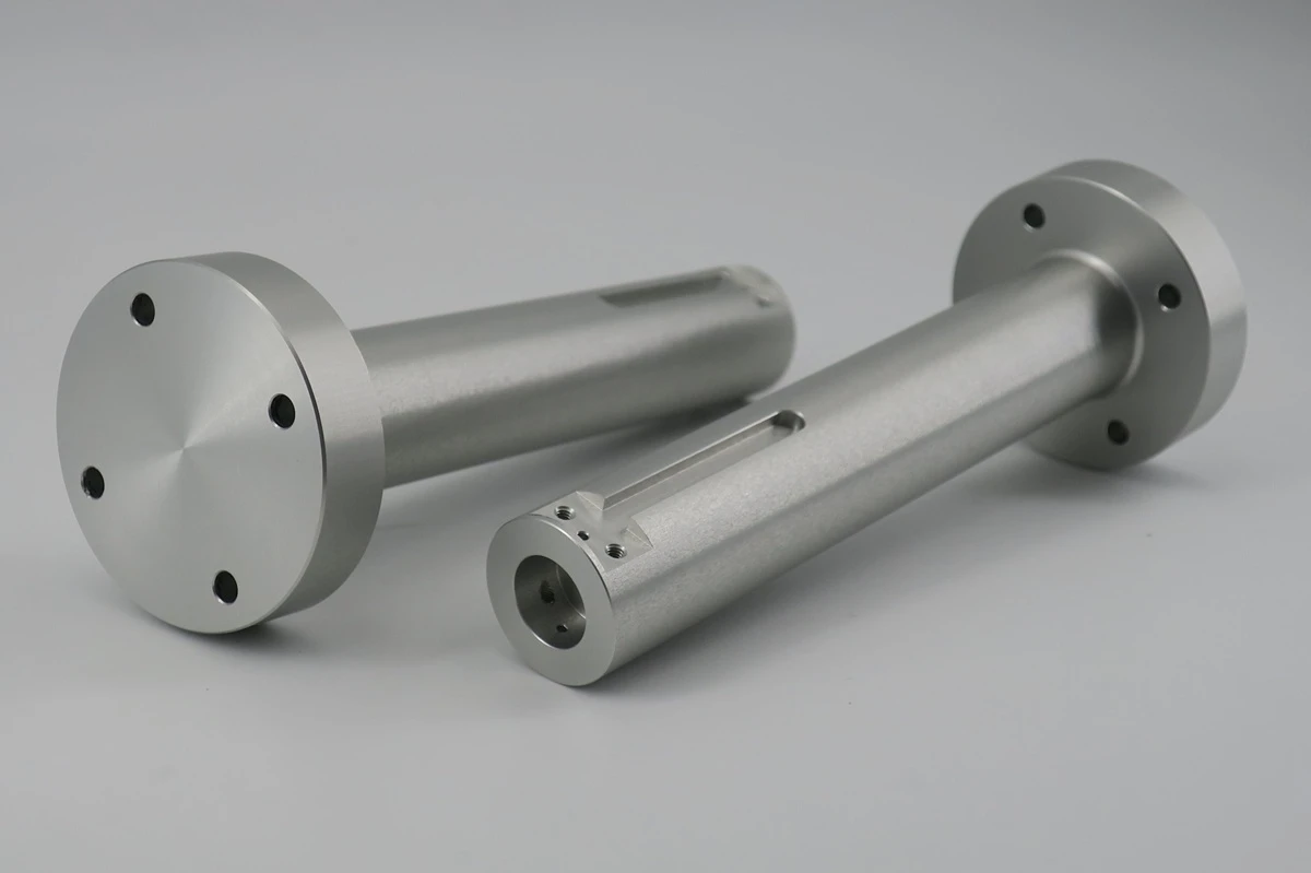
Robotics: sensor mounts, joint brackets, end-effector hardware and structural frames
Primary pain point: balancing low mass, wear, assembly repeatability and batch consistency. Clear anodize works well for many aluminum structures, but sliding contact areas and repeated fastener interfaces should be reviewed separately. For visible robot assemblies, define whether natural batch variation is acceptable rather than turning “silver” into an implied color standard.
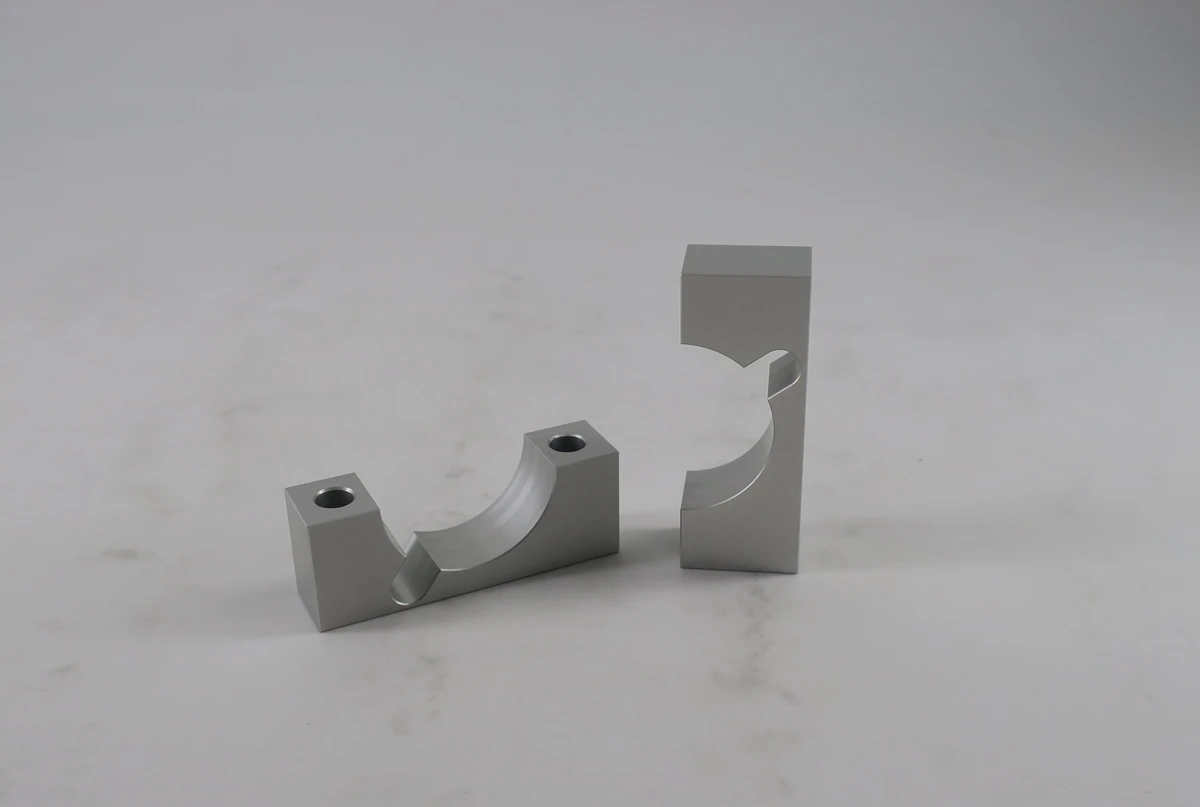
Medical Devices: carriers, housings, brackets and equipment-side aluminum components
Primary pain point: documentation, cleanability, marking and controlled interfaces. Clear anodize can be used on many equipment-side aluminum parts, but the finish alone does not make a component “medical grade,” biocompatible, sterilization-compatible or suitable for patient contact. Those requirements depend on the device design, regulatory pathway, cleaning chemistry, use environment and validated material/process controls. Request traceability and declarations only to the level required by the drawing and quality plan.
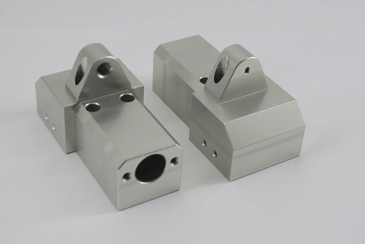
Dental Equipment: imaging, microscope, positioning, valve and instrument-support hardware
Primary pain point: cosmetic appearance plus repeated cleaning and precise assembly. Natural anodize can retain a professional metallic look on brackets, carriers and panels, while masking preserves threads, fits or conductive pads. If disinfectants or cleaning agents are aggressive, validate chemical compatibility instead of assuming universal resistance. Laser-marked identifiers should be checked for readability after the complete finish sequence.
Practical evidence from the supplied manufacturing records shows the type of part mix where these issues arise: 6061-T6 prototype handles, mirror supports, carriages, nests, brackets, filter carriers, camera holders, slide stoppers, finger rests, prism holders, motor brackets, sensor flags, sensor holders and carriers have all appeared with clear/non-dyed Type II Class 1 style requirements. That mix is exactly why a finish page should discuss more than color—it must address fits, masking, laser marking and application context.
RFQ CTA #2 — Have multiple critical interfaces on the same part? Mark bearing seats, ground pads, threads, cosmetic faces, laser-mark zones and “dimension after finish” features directly on the drawing. Send the package with expected annual volume and inspection needs so the machining route and anodize plan can be reviewed together.
Finish Comparison: Clear Anodized vs Black Anodized vs Chem Film vs Hard Anodized
| Finish | Best reason to choose it | Electrical behavior at surface | Appearance risk | Watch-outs |
| Clear / natural Type II anodize | Corrosion protection, surface durability, metallic appearance | Insulating | Alloy and batch shade variation | Dimensional build, masking, seal, cosmetic sample |
| Black Type II anodize | Dark appearance, identification, reduced visible glare in many assemblies | Insulating | Dye shade and fade performance depend on process/environment | Do not assume optical-black performance from ordinary black dye |
| Chem film / conversion coating | Very thin conversion layer, conductive interfaces, paint base | Often selected when electrical conductivity matters, depending on process and requirement | Usually less visually uniform than anodize | Lower wear resistance; chemistry/specification must be controlled |
| Type III hard anodize | Wear and abrasion resistance | Insulating | Usually darker and more variable than Type II | More tolerance impact; seal choice and fatigue/wear considerations |
| Organic clear coat / paint | Decorative barrier or specialized chemical protection | Depends on coating system | Can yellow, chip or vary by coating chemistry | Do not use “scratch resistant clear coat” as a synonym for anodizing |
How to Specify Clear Anodized Machining Parts on a Drawing
A strong drawing separates the finish process from the functional and cosmetic acceptance criteria. Avoid callouts that only say “silver anodized” or “clear anodized” when the part contains precision fits, appearance requirements, or regulated documentation.
Minimum information for a production-ready finish callout
- Base material and temper, for example Aluminum 6061-T6.
- Governing finish requirement: Type II or Type III; Class 1 if a non-dyed military-spec coating is intended.
- Coating thickness or performance requirement when it is functionally important; do not assume a universal thickness from the word “clear.”
- Sealing requirement when not fully defined by the governing specification or when application conditions make seal choice important.
- Masking areas with drawing views, labels or a masking map.
- Critical dimensions identified as applying AFTER finish where needed.
- Cosmetic surfaces, texture (machined, brushed, bead/sand blasted), gloss expectations and approved visual standard.
- Laser-mark content, location, contrast requirement and first-article approval if appearance is critical.
- Compliance/documentation requirements such as certificate of conformance, material traceability, coating certificate, or RoHS declaration when applicable.
- Inspection method and sampling plan for coating thickness, critical dimensions, threads, appearance and marking.
Example Type II callout
ALUMINUM 6061-T6. ANODIZE PER MIL-PRF-8625, TYPE II, CLASS 1 (NON-DYED). MASK SURFACES A, B AND IDENTIFIED THREADS. CRITICAL DIMENSIONS MARKED “AFTER FINISH” APPLY AFTER ANODIZING. COSMETIC FACE: UNIFORM NATURAL APPEARANCE PER APPROVED SAMPLE.
This is an example structure, not a universal specification. The final callout must match the customer’s engineering requirements, coating thickness, seal, inspection method and revision-controlled standards.
Example Type III callout
ALUMINUM [ALLOY/TEMPER]. HARD ANODIZE PER MIL-PRF-8625, TYPE III, CLASS 1. COATING THICKNESS: [DRAWING REQUIREMENT]. MASK BEARING BORES, ELECTRICAL BONDING PADS AND IDENTIFIED THREADS. CRITICAL FITS APPLY AFTER FINISH.
Do not call Type III “clear” if the actual requirement is a silver cosmetic appearance. Non-dyed hardcoat often becomes visibly darker as coating thickness and alloying effects increase.
Drawing-Based Examples: Where Clear Anodize Creates Real RFQ Questions
The examples below are anonymized from supplied manufacturing records. They demonstrate review logic, not universal process instructions; proprietary customer names, part numbers, and unreleased functional claims are intentionally excluded.
Example 1: 6061-T6 medical-equipment carrier with mixed threads and fit-sensitive features
The supplied carrier drawing calls for Aluminum 6061-T6 and a legacy clear Type II Class 1 requirement, while the geometry includes M2, M2.5, and M5 threaded features, closely controlled local dimensions, and model-defined surfaces. The RFQ questions are therefore not limited to color: Which threads may receive coating? Which dimensions apply after finish? Are any interfaces intended for electrical bonding? Is the legacy specification callout contractually fixed or subject to customer-approved clarification? A masking map and post-finish inspection plan reduce the risk of a cosmetically acceptable part that does not assemble.
Example 2: 6061-T6 valve body with multiple ports, threads, and one-sided tolerances
The supplied valve-body drawing also specifies 6061-T6 and clear Type II Class 1, but contains several M2, M3, and M3.5 threaded features, ports, bores, and local dimensions with tight unilateral limits. Coating growth at a bore or thread can matter even when the exterior appearance is acceptable. The safe quotation route is to identify seal or flow interfaces, clarify masking and plug requirements, distinguish pre-finish from post-finish dimensions, and agree how threads and critical bores will be verified after anodizing. The finish should be engineered into the machining allowance and inspection plan rather than treated as the last routing step.
RFQ Checklist for Custom CNC Machined Clear Anodized Aluminum Parts
- 3D CAD model and revision-controlled 2D drawing
- Alloy, temper and any approved material alternatives
- Prototype and production quantities
- Type II or Type III; Class 1/non-dyed requirement; legacy military callout if customer-controlled
- Coating thickness/performance requirement where applicable
- Masking map and electrical bonding/contact surfaces
- Post-finish critical dimensions, GD&T and thread classes
- Cosmetic surface classification, pretreatment and color/texture sample requirement
- Laser marking artwork, location and readability criteria
- Inspection documentation, CoC, traceability and compliance declarations actually required by the project
- End-use environment: indoor, outdoor, repeated cleaning, wear, vacuum, cryogenic, optical or other special condition that changes the finish decision
Quality Control: What Should Be Verified After Clear Anodizing?
Final inspection should focus on the features that anodizing can change. Depending on the drawing and control plan, this can include coating certification, coating thickness, visual appearance, masked areas, post-finish dimensions, thread acceptance, laser-mark legibility and surface damage. The exact method should come from the contract, specification and risk level rather than a generic “100% anodize inspection” statement.
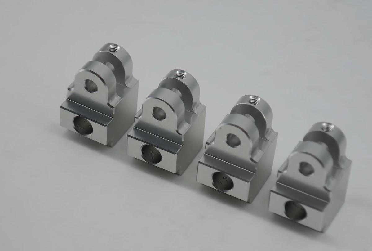
For precision assemblies, it is often useful to separate pre-finish and post-finish inspection. Critical datums or bore sizes can be recorded before anodize to verify the machining process, then rechecked after finish where the final interface is controlled. If masking is used, inspect the boundary for unwanted coating creep, exposed areas outside the mask, burrs, handling damage and electrical contact continuity where applicable.
When appearance is a purchasing criterion, visual inspection must be defined. Lighting, viewing angle, reference sample, acceptable shade variation and the difference between machined, brushed and blasted surfaces all affect the judgment. A supplier cannot reliably control a cosmetic requirement that exists only in the buyer’s expectation and not in the drawing or approved sample.
Ready to quote clear anodized CNC parts? Send the drawing package with alloy, Type II/Type III requirement, masking, post-finish dimensions, cosmetic standard, marking and inspection needs. Rollyu Precision can return DFM questions before production so the finish is engineered into the part rather than added as an afterthought.
Frequently Asked Questions About Clear Anodized Machining Parts
What is clear anodized aluminum?
It is aluminum with an anodic aluminum oxide layer formed electrochemically without intentional dye. The finish is also called natural anodizing or non-dyed anodizing. It typically retains a metallic silver/gray appearance, but the exact shade depends on alloy, pretreatment, thickness and sealing.
Is clear anodized the same as silver anodized?
Not as a technical specification. Buyers often use the terms interchangeably, but “silver anodized” mainly describes appearance. For controlled parts, specify the anodize type/class and separately define the required cosmetic appearance.
What is Type II clear anodize?
Type II under MIL-PRF-8625 is conventional sulfuric acid anodizing. When Class 1 is specified, the coating is non-dyed. The required thickness and sealing should come from the drawing, contract and governing specification rather than from a generic internet value.
What is clear hard anodizing?
The phrase usually means non-dyed Type III hard anodize, commonly Class 1 under MIL-PRF-8625. It is intended for higher wear/abrasion resistance and is often visibly darker than Type II, so “clear” should not be interpreted as transparent or bright silver.
Does clear anodizing change CNC part dimensions?
Yes, it can. Anodizing converts aluminum to oxide and produces coating growth. The dimensional effect depends on the process and feature geometry. Precision bores, fits, threads and datums should be evaluated for allowance, masking or post-finish control.
Can threaded holes be clear anodized?
Yes in many cases, but the decision depends on thread size, fit class, assembly frequency, electrical bonding, sealing and required performance. Critical threads may require masking or pre-finish compensation. Use thread gauges or the specified inspection method after finishing when fit is important.
Is clear anodize electrically conductive?
The anodic oxide itself is electrically insulating. If the assembly needs grounding or chassis bonding, define masked or otherwise controlled conductive contact areas. Do not assume current will pass reliably through an anodized interface.
Can clear anodized parts be laser marked?
Yes. Laser marking can add serial numbers, orientation marks and traceability, but contrast varies with laser parameters, alloy and finish. Use a first article or test coupon when high contrast or machine readability is required.
Is non-dyed clear anodize 100% UV resistant and fade-proof?
No absolute claim is appropriate. Removing organic dye removes one common dye-fading mechanism, but surface appearance can still change with environment, sealing, contamination, abrasion and aging. Validate UV performance if it is a contractual requirement.
Is RoHS-compliant clear anodize automatic?
No. A clear anodize process can be supplied to RoHS requirements, but compliance depends on the actual process chemistry, seals, post-treatments and supplier declaration. If RoHS compliance is required, request the applicable certificate or material/process declaration.
Is clear anodize suitable for medical devices?
It can be used on many medical-equipment components, but the finish itself does not establish biocompatibility, sterilization compatibility, cleanliness level, patient-contact suitability or regulatory compliance. Those requirements must be defined and validated for the device.
Is clear anodize qualified for space, vacuum or UHV use?
Not by default. Vacuum, UHV, space or cryogenic use can impose requirements on cleanliness, sealing chemistry, outgassing, electrical behavior and contamination control. The finish and processor must be qualified to the specific program when those conditions apply.
Is clear anodizing always cheaper and faster than black or colored anodizing?
Not necessarily. Avoiding a dye step may simplify some processes, but total cost and lead time can be dominated by masking, cosmetic pretreatment, batch size, thickness, inspection, documentation and rework risk. Quote the actual drawing rather than assuming a universal cost advantage.
