
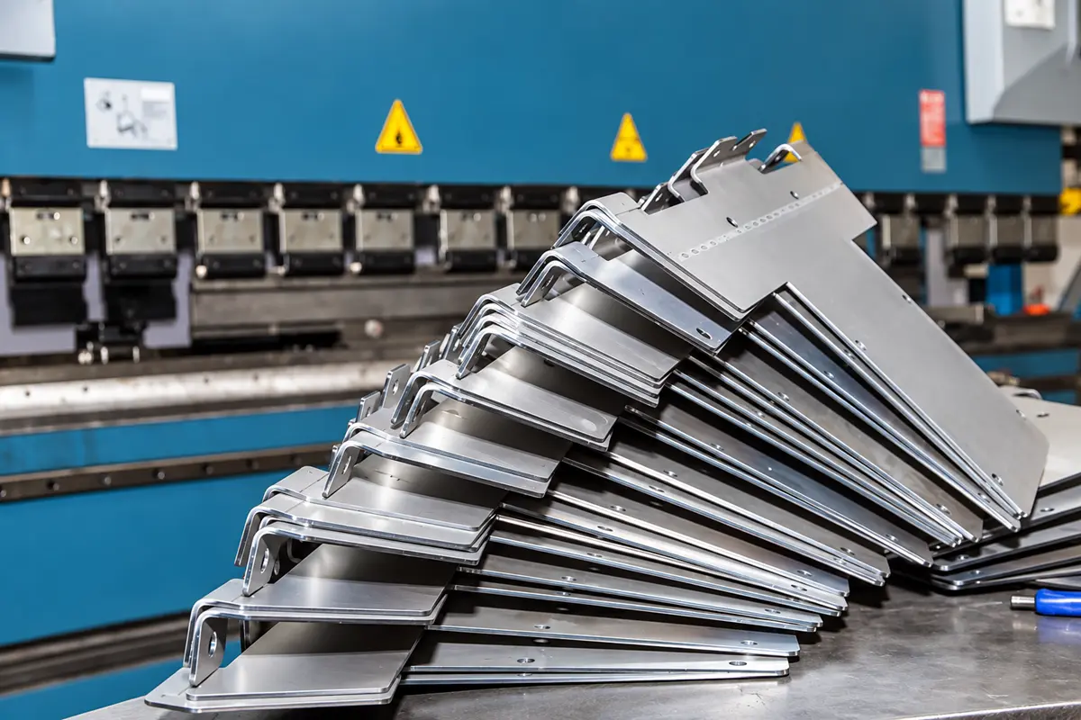

Design a bent bracket or panel from the surfaces and holes that must fit after forming, then work back to the bends and flat pattern. A press brake changes more than the angle between two faces. Material thickness, inside radius, and bend placement can shift a finished flange or mounting hole enough to matter in assembly.
A workable handoff identifies the critical formed dimensions and flags radii, feature clearances, and bend order for the fabricator’s tooling review.
Start With the Formed Part’s Job
Choose the features that locate the part in its assembly before sizing the bends. A bracket usually links two mounting interfaces; a panel often closes an opening or mates with surrounding parts.
| Part | Start with | Control on the formed part | Check in the assembly |
|---|---|---|---|
| Bracket | The faces that seat against the supported and supporting parts | Hole positions relative to mounting faces; distance and angle between those faces | Fastener access and alignment with mating holes |
| Panel | The opening or neighboring parts it fits | Outside envelope, flange positions, and mounting-hole locations | Edge clearance, seating surfaces, and hole alignment |
Bracket Mounting and Alignment
For an L-shaped mounting bracket, identify the face that seats against the frame and the hole pattern that locates the attached component. Control the second leg’s hole locations from the frame mounting face after bending. A flat blank can have accurately cut holes and still miss the assembly position if the bend shifts the second leg.
Panel Outline and Mating Fit
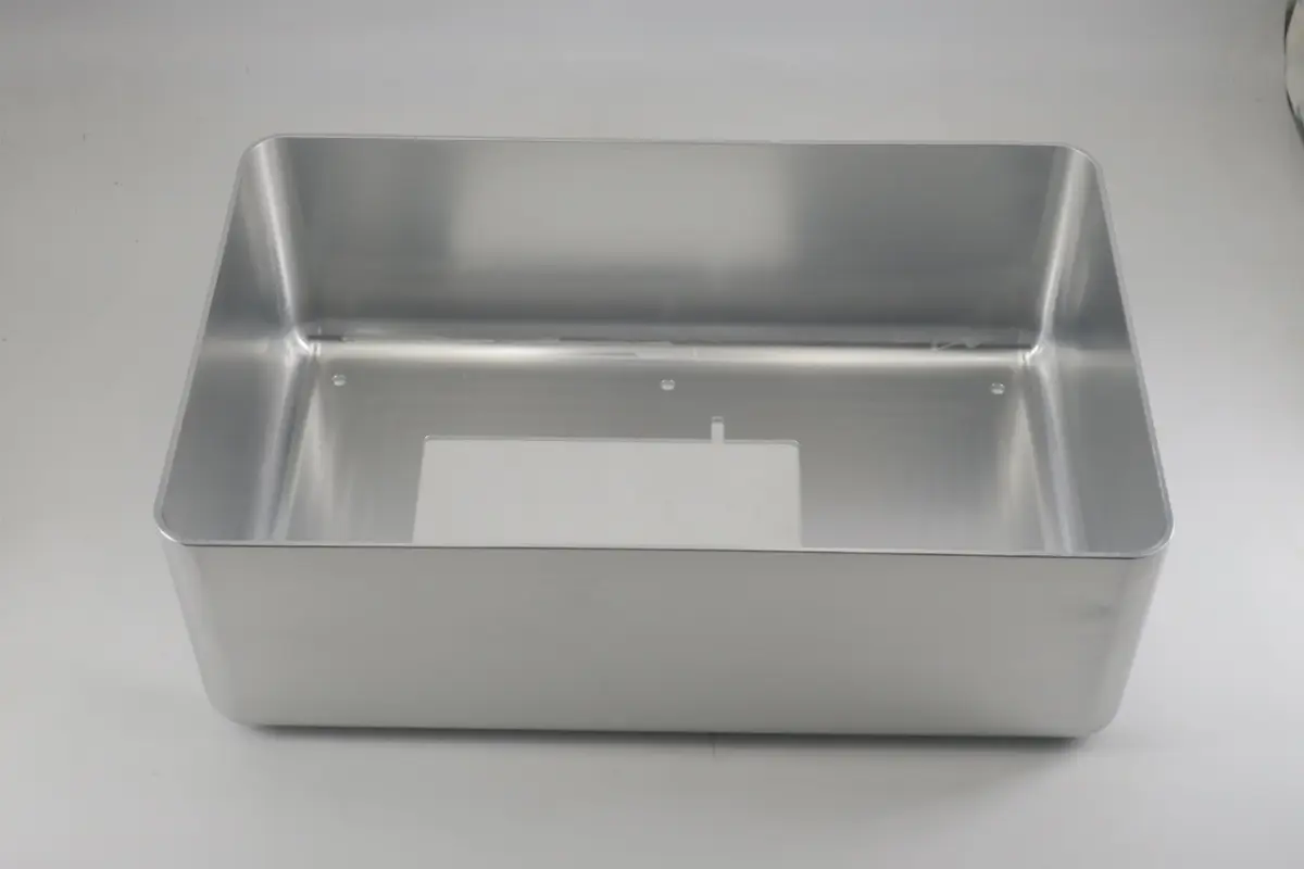
For a panel with turned edges, start with the opening it covers and the faces that contact the surrounding frame. Mark the finished outside dimensions and any mounting holes that must line up after all bends. With multiple flanges, a change in one bend can affect the position of another edge, so dimensioning each flat segment alone does not describe the final fit.
If the panel has clearance on one side but seats against another, identify the seating side on the drawing. That tells the fabricator which formed edge carries the fit requirement.
Turn Functional Requirements Into Bend Geometry
Set the material and basic formed shape before committing to a flat layout. Press-brake tooling and the specified sheet condition affect feasible bends and final feature positions.
Material, Thickness, and Inside Radius
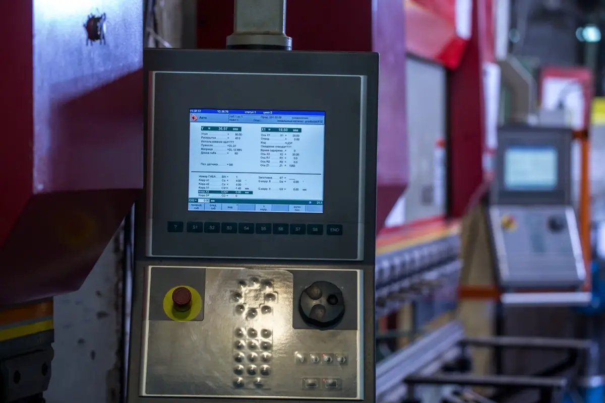
Specify the material grade, condition, and thickness used in the design. The inside bend radius affects strain in the bend and the developed length of the blank; a tighter radius may be unsuitable for some material conditions. Treat a CAD default as a starting assumption, then ask the fabricator to confirm a workable radius for the material and tooling.
If the material or condition changes during sourcing, ask the fabricator to recheck the radius and flat layout against the same finished dimensions.
Flange Length and Bend Sequence
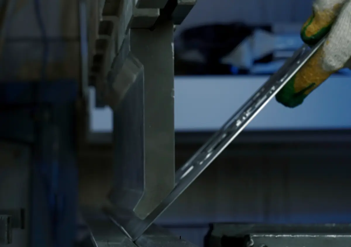
Give each flange enough length for the intended press-brake setup to hold and form it. The needed length depends on the sheet and tool geometry. On parts with multiple bends, inspect the formed model for tool access through the bending sequence. An early bend can block the punch or die from reaching a later bend, even when each bend looks possible on its own.
Holes, Slots, and Bend Relief
Place a functional hole or slot with its formed position in mind. Material near the bend deforms during forming, so a feature close to the bend can distort or move relative to a mating part. If the hole needs to stay close, flag it for a process review rather than borrowing a universal hole-to-bend distance. At a bend ending near an edge or intersecting another feature, a bend relief can give the material room to form; its shape and size depend on the part and process.
For a corner where two flanges meet, inspect the relief in the formed model as well as the flat view. Check that the opening leaves the flanges clear without cutting into a mounting surface.
Bend Allowance and the Flat Pattern
Bend allowance accounts for the material length taken up through a bend. It connects the formed geometry to the flat blank, but its value depends on thickness, radius, bend angle, material, and forming method. Keep the formed dimensions as the design target. Ask the fabricator to check the developed flat pattern against the selected tooling before using the blank as a production reference.
Work Through a Bent Bracket Design
For a two-leg bracket, locate the first leg on its mounting face, then set the position of the second leg’s attachment holes in the assembled condition. That makes the hole-to-face relationship the design target. Position the bend to create the needed offset, select a provisional inside radius and sheet condition, and inspect whether the hole edges and flange length leave room for forming.
If moving the holes away from the bend changes the attachment point, compare a longer leg or a different bend location in the assembly model. Check fastener access as well as hole alignment. For a quote from Rollyu Precision, identify the mounting face, the controlled formed hole position, and the bend angle so the shop can review the radius and flat layout.
Work Through a Multi-Flange Panel Design
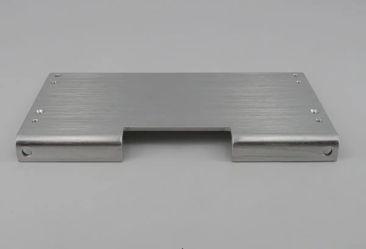
For a panel with multiple turned edges, set the finished outside envelope from the opening and neighboring parts. Locate mounting holes from the surfaces that seat against the assembly, then add the flanges that provide the required edge shape. Review each bend in sequence: an already formed edge may obstruct a later one, and a change in radius or angle may move an outside edge or a hole pattern.
If the fit is tight at one edge, identify that edge and its mating surface as controlled features instead of applying the same tolerance to every flange. Review corner reliefs where adjacent flanges meet. The panel drawing needs to show which dimensions describe the formed part, so a fabricator can adjust the flat pattern without losing the intended final fit.
Hand Off the Formed Design for Manufacturing Review
Send a formed 3D model and a drawing that identifies the mounting or mating faces, critical formed dimensions, hole locations, bend directions and angles, material grade or condition, and sheet thickness. State the assembly clearance or alignment requirement where it drives a dimension. A flat pattern shows the intended blank, but the fabricator needs to check it against the forming setup before it controls production.
Ask the sheet metal fabricator to check the proposed inside radii, short flanges, close-to-bend features, reliefs, bend order, and developed blank. Rollyu Precision offers sheet metal fabrication with press-brake bending for stainless steel and aluminum brackets and panels. The exact material condition, radius, and formed tolerance need a part-specific review. Keep the accepted formed dimensions clear so the fabricator can measure the features that govern assembly.
Frequently Asked Questions
What if the required flange is too short for the press brake?
Ask the fabricator to review a longer flange or a moved bend while preserving the bracket or panel’s mating geometry. The selected die needs enough material to support the bend, and the workable length depends on material, thickness, radius, and tooling. Recheck the finished envelope and hole positions after changing the geometry.
When should the inside bend radius be a controlled drawing dimension?
Control the inside bend radius when it affects clearance with a mating part or another functional requirement. Otherwise, show the intended radius and prioritize the formed dimensions that govern assembly. Ask the fabricator to confirm the workable radius and tolerance for the specified sheet and tooling.
How should I check a first formed bracket or panel before ordering more?
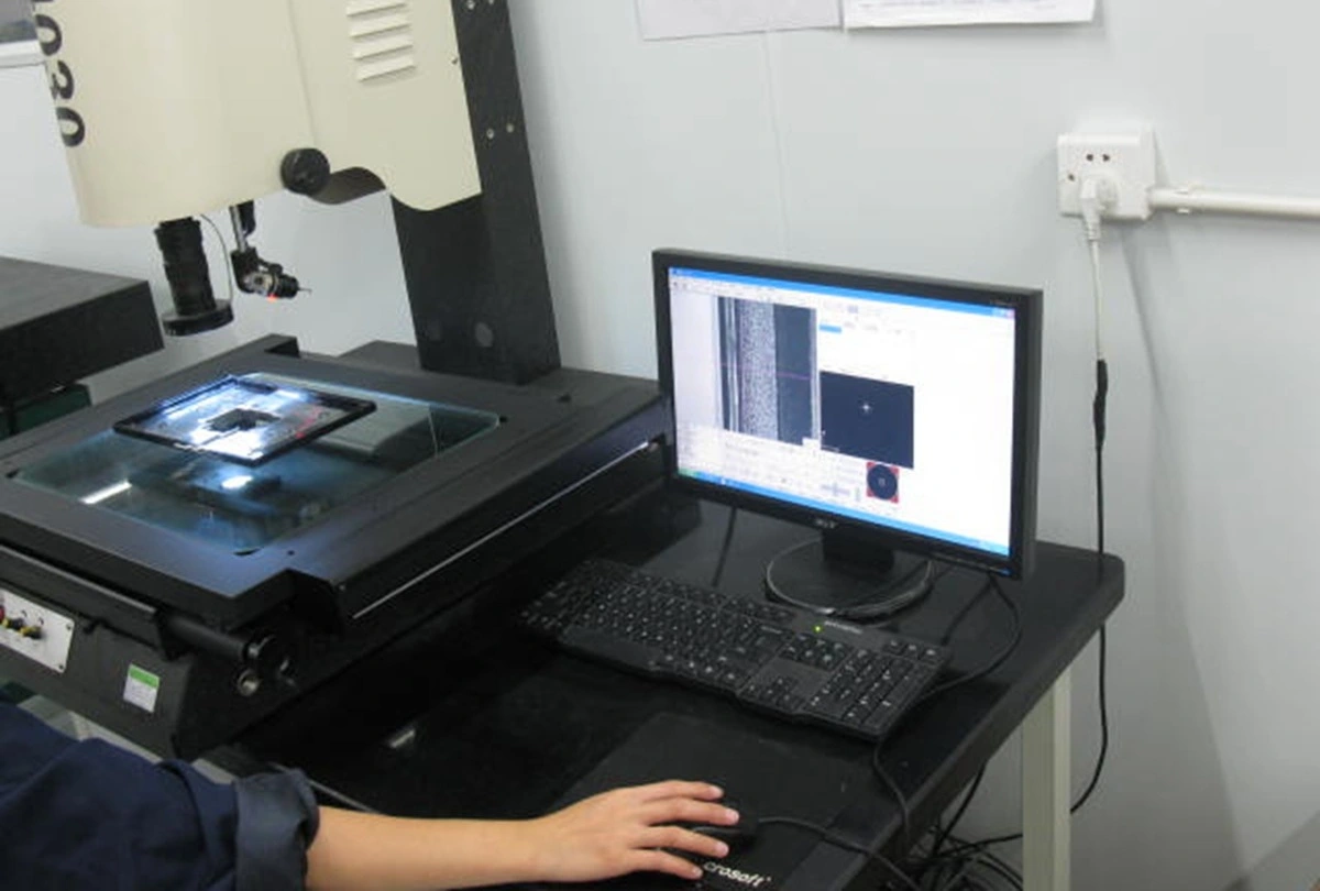
Compare the first formed part with the drawing’s critical dimensions, then test its fit with mating parts when they are available. On the sample, check bracket hole alignment or the panel’s outside envelope and contact faces. Agree with the fabricator on which dimensions to measure and whether the project needs a sample inspection record.
