


Start wafer-handling part design with the wafer-contact strategy, functional datums, and inspection plan, not a general tolerance note. A part can meet nominal dimensions and still create handling risk if its support points, alignment features, or sensitive edges do not match the equipment’s actual motion and wafer condition.
This guide helps equipment engineers and sourcing teams define the features, materials, inspection evidence, and RFQ inputs that make a wafer-handling part easier to evaluate before release. The requirements should come from the equipment owner, especially when wafer size, thickness, warpage, process environment, or cleanliness controls are specific to a tool.
What Makes Wafer Handling Parts Different From General CNC Components?
Wafer handling parts must control how a fragile, process-sensitive wafer rests and locates during real equipment motion. General dimensions matter, but the contact pattern, installed datums, and alignment path usually determine whether the part handles the wafer as intended.
Wafer Contact Strategy
Define the wafer contact plan before the supplier starts machining. The drawing should identify permitted contact locations, no-contact zones, sensitive edges, and the surface requirements that apply to active contact areas.
A broad finish callout can hide the surfaces that actually need control. The contact plan should separate the wafer-facing features from general exterior surfaces.
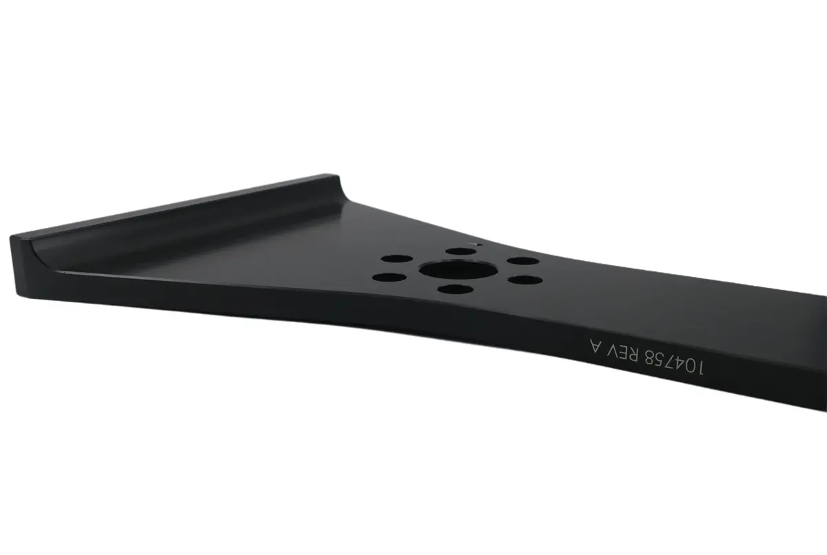
Functional Datums
Set datums from the interfaces that establish the installed position of the end effector or fixture. A datum scheme based only on convenient machining faces can produce an inspection result that looks acceptable while the wafer plane or tool interface shifts in the equipment.
Alignment Control
Set alignment from the wafer reference and the machine interfaces that govern repeatable placement. The drawing should identify the hole, pin, shoulder, or locating surface that controls position, then apply GD&T only where the relationship affects handling. This approach keeps critical alignment requirements separate from dimensions that do not affect the wafer path.
Which Design Features Should Be Defined Before CNC Machining?
Define the support, stiffness, interface, and edge requirements before a supplier chooses workholding or tool paths. This prevents a manufacturable drawing from becoming a difficult-to-qualify part after machining.
Support Geometry
State the number, location, and shape of support features, together with the intended wafer size, thickness, warpage condition, and clearance around the support pattern.
A part designed for a nominally flat wafer may need a different contact pattern when the equipment owner expects thinner wafers or defined warpage conditions. The drawing should identify which condition controls the geometry.
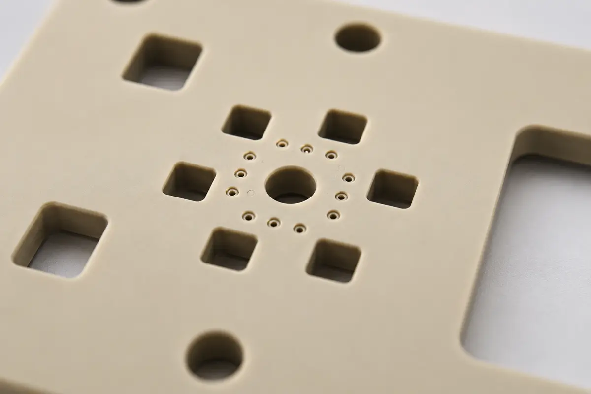
Deflection Control
Identify slender arms, thin webs, long cantilevers, and other features that can move under machining or equipment load. CNC DFM guidance flags thin walls and tall unsupported features as higher-risk geometry, so the drawing should define stiffness-critical areas instead of applying a blanket tolerance to the entire part.
Interface Geometry
Define mounting patterns, locating pins, reference shoulders, assembly clearances, and moving clearances as functional features. State the assembly condition used for inspection.
A free-state measurement may not represent the mounted relationship. The inspection setup should reproduce the locating sequence when that sequence controls wafer position.
Edge Conditions
Call out edge breaks, radii, or prohibited burr locations at wafer-facing and sensor-facing areas. “Deburr” alone is not an acceptance criterion for a sensitive edge. The requirement should identify the affected feature, permitted edge form, and inspection method, including whether a chamfer or fillet callout controls the transition.
| Feature group | Define before machining | Buyer risk if left generic |
|---|---|---|
| Wafer supports | Contact locations, geometry, and intended wafer condition | The part may support the wafer at unintended points. |
| Alignment features | Functional datums, locating sequence, and relevant GD&T | Inspection may not represent installed position. |
| Slender sections | Stiffness-critical zones and allowable deflection criteria | Machining or operating loads may change functional geometry. |
| Sensitive edges | Edge condition, affected areas, and acceptance method | Burrs or sharp transitions may remain in handling zones. |
How Should Engineers Specify Materials and Surface Requirements?
Material and surface requirements should describe the equipment environment and the sensitive areas they protect. A material name or a general finish note is incomplete when it does not state the applicable surface, cleaning expectation, or traceability need.
Material Selection
Material selection should name the approved grade, material condition, and required supplier documentation. For semiconductor CNC machining, Rollyu Precision lists aluminum, stainless steel, titanium, engineering polymers, ceramics, Invar, and Kovar among its machinable materials, but material fit for a wafer-handling part remains an equipment-level decision.
The engineering team should tie the selection to the documented operating environment, contact strategy, thermal needs, and any customer material standard.
Surface Requirements
Apply each finish or treatment to the surface that affects wafer contact, sliding, alignment, sealing, or cleanliness. State the measurement method when a numeric requirement is critical, and separate cosmetic requirements from functional requirements.
Do not assume that a smoother finish is automatically suitable for every handling surface. The equipment requirement should determine the surface condition.
Contamination Control
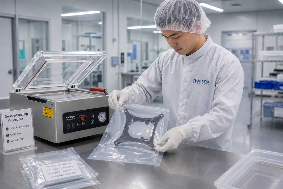
Convert contamination concerns into release requirements that a supplier can verify. Identify restricted materials or processes, cleaning method, packaging condition, handling controls, and any particle or cleanliness test the equipment owner requires. If the project requires a cleanroom process or particle-inspection method, include the applicable specification and acceptance limit because CNC machining alone does not imply either control.
How Should Wafer Handling Parts Be Inspected Before Release?
Inspection should prove the geometry that governs wafer support and equipment fit, then document the result against the released drawing. A general dimensional report may be insufficient when the part has wafer-facing zones or multiple installed interfaces.
Geometric Verification
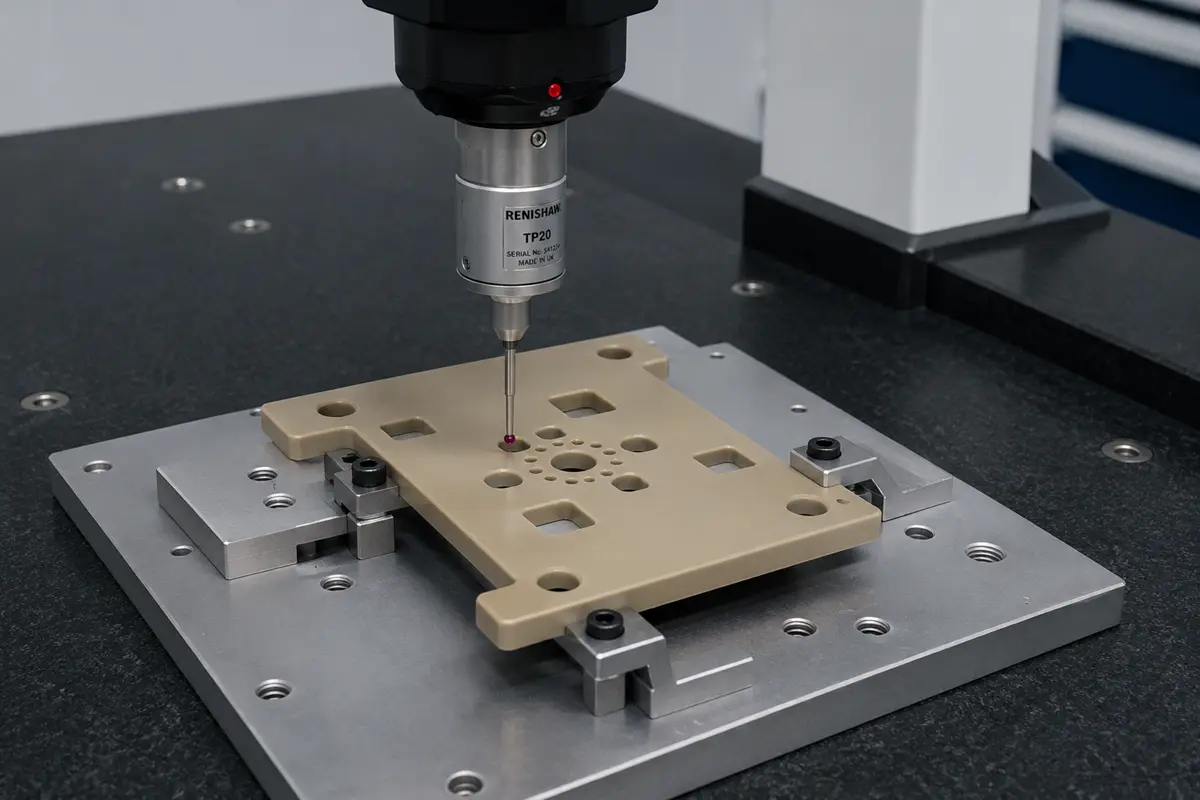
Use the drawing’s functional datum scheme for CMM inspection of critical position, profile, flatness, parallelism, and interface relationships. Rollyu Precision supports CMM, in-process, and final dimensional inspection, but the buyer should identify the critical characteristics and required report format before production.
Sensitive-Area Inspection
Inspect wafer-facing support surfaces, edge conditions, and other defined sensitive areas using the acceptance method named on the drawing. Visual or optical inspection can document appearance and defined edge conditions, while dimensional methods verify geometric requirements.
A general cosmetic check does not replace a defined functional requirement.
Traceability Records
Request records that connect the released part to its material, revision, lot, inspection result, and required process documentation. This record set can include material traceability, Material Test Reports, dimensional or CMM reports, Certificates of Conformance, and a first article inspection report when required.
The document package must match the release scope defined in the RFQ. Do not request a generic record package when a wafer-facing or alignment feature needs a specific report.
What Should Buyers Include in a Wafer Handling Parts RFQ?
A usable RFQ gives the machining supplier the design intent, installed interfaces, and evidence needed for release. It should separate functional requirements, equipment-owner controls, and required delivery documents.
Design Inputs
Provide the released 3D model and 2D drawing. Include:
- Revision level, critical dimensions, functional datums, and GD&T.
- The wafer configuration the end effector handles.
- An assembly view when it clarifies installed orientation or contact zones.
A supplier quoting CNC machining parts cannot reliably infer those functional relationships from a nominal part model alone.
Interface Requirements
State the mating interfaces, locating method, fasteners, pins, clearance zones, and any motion envelope that affects the part. If the end effector works with a robot or a specific handling module, identify the controlling interface rather than asking the supplier to infer it from nominal dimensions.
Acceptance Criteria
List measurable release criteria for support features, alignment geometry, sensitive edges, surface requirements, and cleanliness controls. Each criterion should name the feature, limit, datum reference when relevant, and verification method. Requirements without an acceptance method are more likely to create disagreement at inspection.
At the supplier-selection stage, Rollyu Precision can review a project against its CNC machining, DFM, CMM inspection, and material-traceability requirements.
Documentation Requirements
Name the documents required with the order, such as:
- First-article and CMM reports.
- Material documentation and Certificates of Conformance.
- Packaging records and approved deviation records.
Revision Control
Put the drawing revision, model revision, inspection-plan revision, and approved deviation status in the RFQ and purchase order. When a contact surface, material, finish, or interface changes, the revision record should show whether the existing inspection plan and qualification evidence still apply.
Frequently Asked Questions
Can One Wafer-Handling End Effector Be Used for Different Wafer Sizes, Thicknesses, or Warpage Conditions?
One end effector can support different wafer conditions only when its defined support geometry, contact pattern, clearances, and handling sequence remain suitable for each condition. A size, thickness, or warpage change can alter the support points or clearances near equipment. The equipment owner should review the intended wafer range before treating one design as interchangeable.
When Should a Buyer Request a First Article for a Wafer-Handling Part?
Request a first article when the part introduces a new wafer-contact strategy, functional datum scheme, material or finish, critical interface, or revision that could change handling behavior. The first article should focus on the characteristics that govern support and alignment, not only on envelope dimensions. Rollyu Precision can support FAI documentation when the RFQ defines the required features and report format.
What Makes a Wafer-Handling Part More Expensive to Machine?
Cost rises when the part needs complex workholding, thin or slender geometry, tightly controlled alignment features, sensitive edge requirements, specialized finishing, or expanded inspection documentation. The cost effect depends on the drawing, material, quantity, and acceptance scope. Separating functional critical features from noncritical geometry can help the supplier plan the right machining and inspection effort.
When Does a Material or Finish Change Require an Equipment-Level Review?
Request an equipment-level review before release whenever a material or finish change affects a wafer-facing surface, contact behavior, installed interface, operating environment, cleaning method, or specified cleanliness control. The engineering team should decide whether the existing qualification evidence still covers the changed condition. A supplier should not infer that one material or finish is interchangeable with another.
What Must Be Requalified After a Wafer-Handling End Effector Is Replaced or Revised?
Requalification should cover the changed interfaces, wafer-support geometry, alignment references, sensitive surfaces, and the equipment-level handling sequence affected by the revision. The exact scope belongs to the equipment owner because it depends on the tool, wafer condition, and release procedure. Keep the requalification record linked to the revised drawing and inspection evidence so the replacement part is not treated as identical without proof.
