
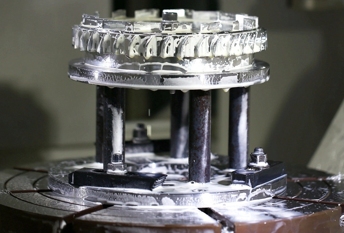

Jigs and fixtures control a workpiece in different ways. A jig guides a cutting tool, while a fixture locates, supports, and clamps the part without guiding the tool. Fixtures are more common in CNC machining because the programmed machine controls the tool path.
This guide explains the difference between jigs and fixtures, common workholder types, how CNC fixtures control a setup, and how shops manufacture custom workholding. It also shows Design Engineers and Manufacturing Engineers what to define before requesting a fixture quote.
What Are Jigs and Fixtures?
A jig is a workholder that also guides a cutting tool. A drill jig, for example, can use hardened bushings to place and guide a drill at specified hole locations. This arrangement controls the relationship between the workpiece and the tool during the operation.
A fixture locates, supports, and holds a workpiece without guiding the cutting tool. Milling fixtures, lathe fixtures, vise jaws, and fixture plates establish the part position while the machine controls tool motion. This division of work makes CNC fixtures more common than traditional tool-guiding jigs in modern milling and turning.
Fixturing is the broader workholding method used to establish and maintain part position during manufacturing or inspection. Locators establish position, supports resist process loads, and clamps secure the workpiece against both. Clamping cannot compensate for an unclear or unstable locating scheme.
How Does a Jig Differ From a Fixture?
Tool guidance is the defining difference. A jig guides the cutting tool and controls the workpiece. A fixture controls the workpiece while the machine or operator guides the selected CNC cutting tools.
| Decision factor | Jig | Fixture |
|---|---|---|
| Primary job | Locates and holds the part while guiding the cutting tool | Locates, supports, and holds the part without guiding the cutting tool |
| Tool guidance | Built into the jig, often through a bushing or template feature | Provided by the machine, program, or operator |
| Common operations | Drilling, reaming, and some boring operations | Milling, turning, grinding, sawing, assembly, and inspection |
| Machine relationship | May be handheld, positioned on a machine, or attached to a work surface | Commonly mounted or referenced to a machine table, spindle interface, pallet, or work surface |
| Typical examples | Drill jig, template jig, plate jig, box jig | Milling fixture, soft jaws, angle-plate fixture, indexing fixture, assembly fixture |
| CNC role | Useful for physical tool guidance or a repeatable manual operation | Establishes the relationship between the workpiece and the programmed machine coordinates |
Weight and attachment do not define the difference. Machining loads often require a rigidly mounted fixture, although the fixture may still be removable or modular. A large jig may also need secure mounting. The test is whether the workholder guides the cutting tool.
Common Types of Jigs and Fixtures
Jigs and fixtures are usually classified by their form, operation, or method of controlling the workpiece. Part geometry, tool access, orientation, production pattern, and changeover needs determine which type fits the job.
Drill and Boring Jigs
Drill jigs position the workpiece and guide drills, reamers, or related hole-making tools through bushings. The bushing sets the tool location and limits sideways movement as the tool enters the part. A boring jig applies the same guidance principle when the boring operation and machine arrangement require it. These jigs suit repeated hole patterns when the operation cannot rely on programmed machine coordinates, but they still need stable locating surfaces and support near the drilling load.
Plate, Template, and Box Jigs
A template jig places a guide pattern against the part. A plate jig carries the guide features and locators on a supporting plate. An open jig gives access from one primary side, while a box jig surrounds more of the part and can present different faces after repositioning. None of these forms has an inherent accuracy level. Accuracy depends on the locator scheme, guide condition, part variation, tool condition, and seating consistency.
Plate, Angle-Plate, and Vise-Jaw Fixtures
A plate fixture mounts locating and clamping elements on a flat base. An angle-plate fixture sets the part at a defined orientation to the machine table, and vise-jaw fixtures use standard or custom jaws to match suitable part profiles. Each design must support the workpiece near the cutting load while leaving clearance for the cutter, probe, chips, and fasteners.
Indexing and Multi-Part Fixtures
An indexing fixture moves the workpiece through controlled angular or linear positions. The mechanism must seat against its intended reference before machining continues.
A multi-part fixture holds multiple workpieces in one setup. A multi-station fixture may place those parts at different stages of an operation sequence. Both layouts can reduce handling, but they require clear loading orientation, adequate tool clearance, chip control, and clamping that does not shift one part when the operator secures another.
How Fixtures Work in CNC Machining
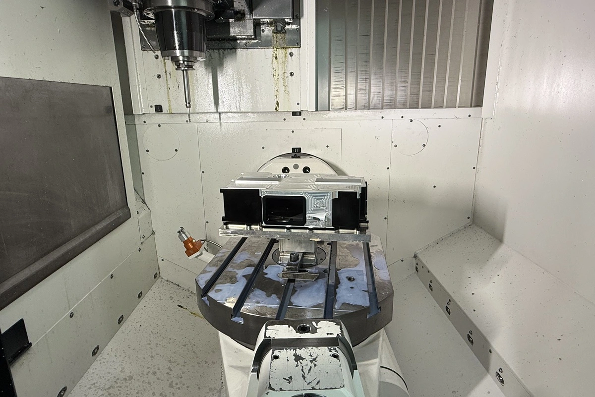
A CNC fixture establishes the relationship between the workpiece, machine coordinates, cutting tool, and inspection method. Locating, supporting, clamping, and access must work together, but each function solves a different setup problem.
Locating the Workpiece
Locators set the part position relative to the machine coordinate system. A common 3-2-1 locating method uses three contact points on a primary plane, two on a secondary plane, and one on a tertiary plane to constrain a prismatic part. Flexible, cylindrical, or complex parts may need a different scheme.
Locators work best on stable, specified surfaces. Extra contact points can create conflicting constraints that keep a variable part from seating against its intended datums.
Supporting Cutting Loads
Supports resist cutting forces without allowing the part to rock or bend. Place support near loaded features and direct the cutting force into solid locators or support points instead of depending on friction alone. Thin walls and long projections may require added support, a different cutting sequence, or a lower machining load.
Clamping Without Distortion
Clamps hold an already located workpiece against its supports. The clamp direction should reinforce seating instead of lifting or sliding the part. Excessive force can distort thin walls, mark finished surfaces, or create a temporary position that changes after unclamping.
Loading consistency also depends on clamp sequence and contact. A defined sequence and a visible seating check help operators repeat the setup. When finished surfaces need protection, shaped faces or non-marring pads may be suitable if their materials can withstand the process conditions.
Preserving Tool and Inspection Access
A fixture must leave enough room for every device that enters the setup. Check the complete motion envelope, including:
- the cutter body and holder through the full programmed path;
- probes or gauges that must reach datum and inspection features;
- fasteners and adjustment points needed during loading or service;
- chip and coolant paths around locators and beneath the workpiece.
These access checks belong in the DFM review. A clamp that clears one tool may still block a later operation or prevent measurement of a critical feature.
How CNC Machines Jigs and Fixtures
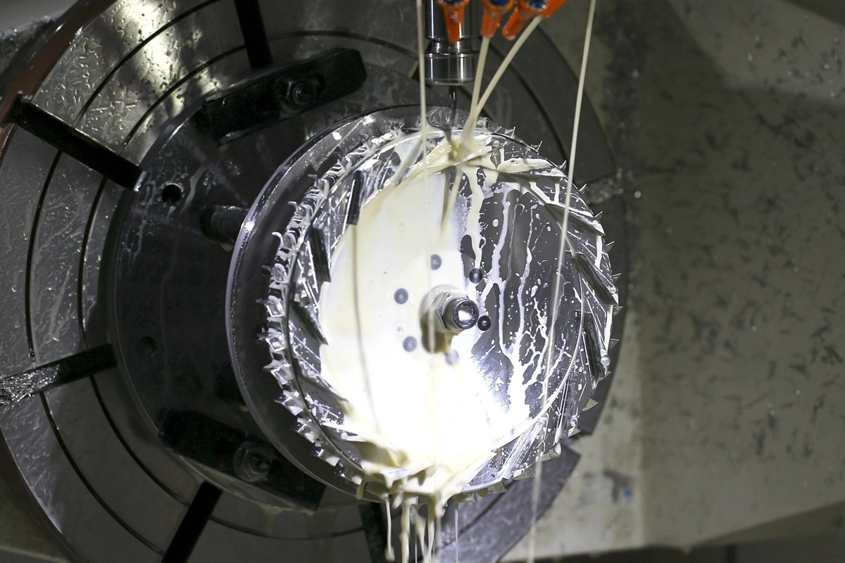
Manufacturing a jig or fixture starts with the workholding strategy, then turns that strategy into controlled mounting surfaces, locating features, clamp interfaces, and verification steps. A machined plate becomes a workholder only after the design defines those functions and the assembly provides them.
Choosing the Workholder Strategy
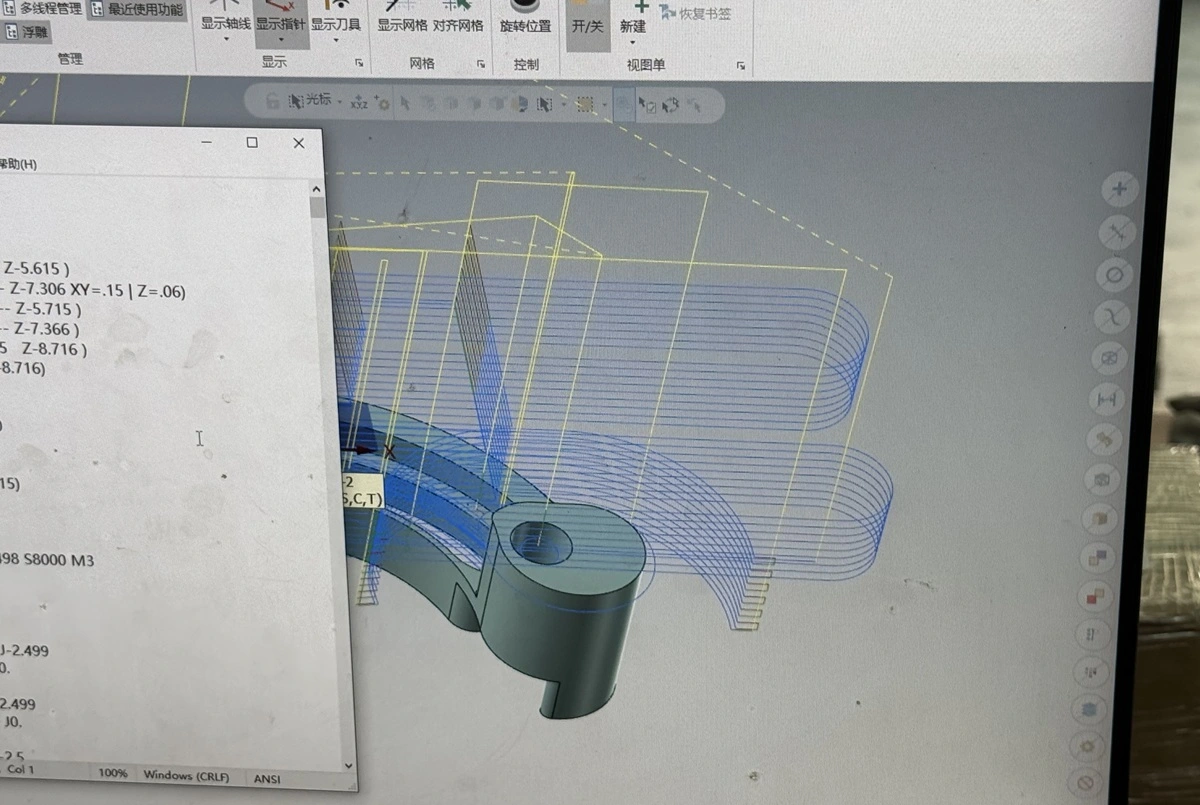
Start by deciding whether a standard vise, chuck, collet, or another general-purpose workholder can control the part. Move to modular or dedicated tooling when the geometry, cutting load, orientation changes, tool reach, loading method, production pattern, or changeover target makes standard workholding unsuitable.
Material and construction choices follow the application. Fixture stiffness, wear at contact points, environmental exposure, weight, repair needs, and expected reuse may call for different materials within one assembly. Replaceable locators, bushings, and wear elements can confine maintenance to the surfaces that see repeated contact.
Machining the Base and Locating Features
Machine the workholder in a sequence that preserves its datum relationships:
- Establish the base mounting surfaces and primary references.
- Machine locator holes, pockets, slots, and component interfaces from the defined datum scheme.
- Verify the workpiece-control features before installing clamps and other hardware.
Rollyu Precision’s CNC machining parts service covers custom jigs, fixtures, tooling plates, and machined workholding components. CNC turning can produce round pins, bushings, and arbor-style elements, while wire EDM may suit features that milling or turning cannot produce efficiently. The drawing must define the required geometry, material, and acceptance criteria for each component.
Adding Hardware and Verifying the Setup
Locators, supports, clamps, fasteners, bushings, stops, or sensors turn the machined body into a working fixture. The assembly should also leave service access where the design uses adjustable or replaceable components.
Before production release, mount the workholder on its intended interface and load representative parts. Verify seating, clamp clearance, tool travel, chip evacuation, and access to inspection features. Use the drawing or approved acceptance plan for dimensional checks instead of applying an assumed tolerance.
Choosing General-Purpose, Modular, or Dedicated Fixtures
The right workholder balances flexibility, setup effort, and repeat-cycle needs. Production quantity matters, but geometry, loading time, process risk, available machines, and expected design changes can alter the choice.
| Workholder strategy | Best fit | Changeover | Reuse | Initial engineering effort | Main limitation |
|---|---|---|---|---|---|
| General-purpose | Prototypes, varied parts, and geometries that fit standard vises, chucks, or collets | Usually fast when the part fits existing hardware | High across unrelated jobs | Low | May require more operator alignment or restrict access |
| Modular | Product families, changing designs, and setups that can share configurable bases and components | Moderate because the setup team must reposition and verify components | High within the modular system | Moderate | Additional joints and components can complicate setup |
| Dedicated | Stable part designs and repeated operations that benefit from fixed loading and locating | Fast after process validation | Low outside the intended part or family | High | Upfront design, build, storage, and change risk |
Choose a dedicated fixture from the full production case, not from a universal quantity threshold. Compare setup time, operator input, scrap or rework exposure, inspection needs, expected design life, and the cost of a future part revision. For automation assembly, calibration, and testing applications, include loading, sensor, and gripper interfaces in the fixture decision.
RFQ Inputs for Custom Jigs and Fixtures
A useful RFQ for custom jigs and fixtures defines the part, operation, machine interface, loading method, and acceptance criteria. A request for “a fixture for this part” leaves design assumptions unresolved and makes supplier quotes difficult to compare.
Part and Process Inputs
Provide the files and controls that define what the workholder must locate and protect:
- the current 3D model and a controlled technical drawing for CNC machining when both are available;
- part material, incoming condition, planned operation, and expected sequence;
- critical features, datum scheme, and surfaces that need protection;
- features that must remain accessible for machining, assembly, inspection, calibration, or testing.
If the datum scheme is provisional, label it for engineering review rather than presenting it as approved.
Machine and Loading Inputs
Identify the machine or mounting interface, work envelope, table or pallet pattern, spindle and holder clearance, chip and coolant conditions, and any rotary-axis limits. The RFQ should also state whether loading is manual, assisted, or automated, along with the part orientation and expected changeover pattern.
Automation projects may require interfaces for sensors, grippers, stops, or error-proof loading features. Rollyu Precision can machine custom jig and fixture components for automation equipment from approved drawings and models. The engineering team still needs to review project-specific assembly, calibration, testing, and control interfaces before approving the workholder concept.
Inspection and Acceptance Inputs
The project owner should define how the team will accept the finished workholder. Relevant inputs may include the fixture datum scheme, controlled dimensions or relationships, the reference or representative part, project-defined repeatability criteria, and required inspection or material records.
Rollyu Precision can review drawings and models for custom CNC workholding components. The engineering owner and sourcing team should separate confirmed acceptance criteria from open design questions so unresolved points do not become assumed requirements in the quote.
Frequently Asked Questions
Can jigs and fixtures be 3D printed?
Yes, some jigs and fixtures can be 3D printed when the material suits the load, temperature, wear, accuracy, and service life. Printed workholders can support prototypes, light-duty positioning, non-marring contact, or complex nests. Machined metal is often more suitable when cutting loads, wear, heat, or long production use exceed the printed material’s capability.
Does a CNC fixture guarantee part tolerance?
No. A CNC fixture supports consistent workpiece location and restraint, but machine condition, programming, cutting tools, material behavior, temperature, setup, and inspection also affect the finished result. Verify the fixture as part of the complete manufacturing process.
What is the difference between a fixture and a fixture plate?
A fixture plate is the mounting base or interface used to position workholding components. A complete fixture adds the locators, supports, and clamps needed to control the workpiece for a defined operation. The same fixture plate may serve a dedicated or modular setup, but the plate alone may not provide complete workholding.
