
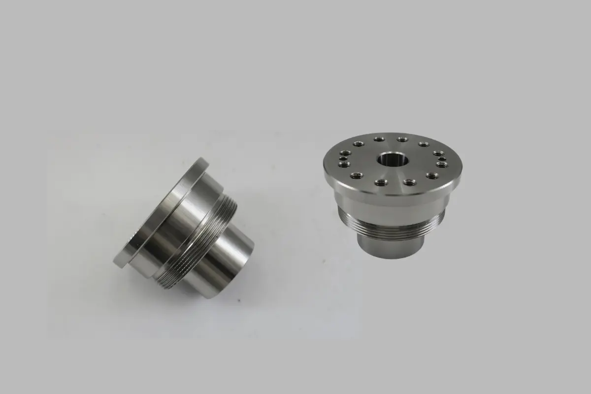

Specify machined surface roughness by naming the parameter, limit, units, applicable surface, governing standard, and inspection conditions. A callout such as “Ra 0.8 µm” can still be incomplete when part function depends on lay, isolated valleys, post-processing, or measurement direction.
Clear roughness specifications connect design intent with machining and inspection. This guide explains how to choose Ra or Rz, place the requirement on a CNC drawing, control the machining variables that affect texture, and prepare inspection and RFQ information.
What Does Machined Surface Roughness Measure?
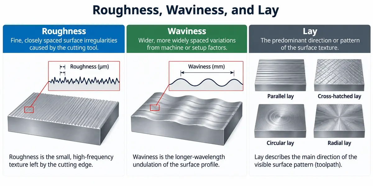
Machined surface roughness measures the small, closely spaced height variations left by cutting tools or finishing abrasives. Surface texture also includes larger waviness and the direction of the machining pattern, called lay.
Ra for Average Profile Height
Ra (Roughness Average) is the arithmetic mean of absolute profile-height deviations from a mean line over the evaluation length. Ra provides a repeatable average for general texture control, which is why it appears often on engineering drawings and inspection reports.
An average does not describe every profile feature. Two surfaces can return the same Ra while one has shallow, regular tool marks and the other has an isolated deep valley. Ra controls average texture, but it does not define scratches, pits, waviness, or lay.
Rz for Peak-to-Valley Variation
Rz describes peak-to-valley variation rather than an average height. ISO 21920-2 and ASME B46.1 use their own definitions and reporting rules, so an Rz value needs a named governing standard. Rz adds useful control when an isolated valley or high peak matters more than the average, such as on a sealing or sliding surface. Ra and Rz use different calculations, and a fixed conversion factor cannot replace the specified parameter.
Roughness, Waviness, and Lay
Roughness, waviness, and lay describe different parts of surface texture:
- Roughness covers the fine profile irregularities produced by cutting edges and abrasive particles.
- Waviness covers more widely spaced variation, often associated with vibration, cutter deflection, workholding movement, or thermal drift.
- Lay describes the dominant direction of the machining pattern, such as parallel, perpendicular, radial, or multidirectional.
A part can meet its Ra limit and still show chatter, a directional tool pattern, or a scratch across a seal track. Add the applicable waviness, lay, or defect control when the verified part function requires it. A roughness number alone does not accept or reject every surface condition.
Choosing a Surface Roughness Requirement
Choose a surface roughness requirement from the job of each face, then confirm that the planned machining and inspection methods can produce and verify it. No universal Ra or Rz value applies to all bearing seats, seal faces, cosmetic panels, or coating surfaces.
Surface Function and Operating Demands
Tie the requirement to contact, motion, sealing, coating, or appearance. A locating face may need a different control from a nearby clearance face. A seal-contact surface may need limits on valleys and lay, while a cosmetic face needs separate appearance and defect criteria.
The design authority should set the functional limit from the mating system, load, lubricant, seal design, coating specification, or validated test. A machining partner can check whether the requested result is manufacturable and measurable, but the part’s functional acceptance requirement remains a design decision.
| Surface application | Useful specification elements | Inspection evidence | Cost and processing impact |
|---|---|---|---|
| General mounting or clearance face | Ra limit when average texture affects fit or assembly | Ra reading at named locations | Standard milling or turning feeds; lower processing and inspection effort |
| Sliding or bearing contact | Ra plus any needed Rz, lay, or waviness control | Profile trace and recorded settings | May add a finishing pass, wiper insert, or cylindrical grinding operation |
| Static or moving seal contact | Ra, valley depth parameters, lay direction, and defect limits | Readings across the functional zone plus visual inspection | May require limits on transverse tool marks and a separate finishing operation |
| Coating or adhesive preparation | Required texture, preparation process, and inspection stage | Pre-process or final-surface record as specified | Fine pre-machining adds no value when later abrasive blasting removes the texture |
| Cosmetic face | Measurable roughness plus an appearance standard when needed | Roughness data and a separate visual result | Ra does not define color, gloss, scratches, or pattern uniformity |
Limit Fine Callouts to Critical Features
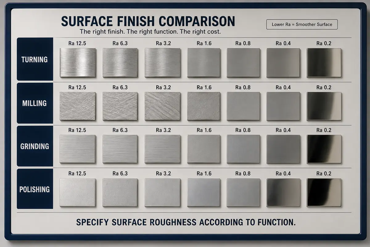
Apply tighter texture limits only where part function supports them. Standard CNC milling and turning commonly produce Ra 1.6–3.2 µm (63–125 µin) with conventional cutting tools. Calling for Ra 0.8 µm (32 µin) or Ra 0.4 µm (16 µin) across an entire part can add finishing passes, slower feeds, different inserts, grinding, or more inspection. Use a general drawing note only when the same requirement applies to the remaining surfaces, and point stricter limits to the exact faces or zones that need them.
Confirm Process, Material, and Measurement Access
Check feasibility before releasing the drawing. Milling, turning, grinding, polishing, and wire EDM leave different profile patterns. Material behavior, part stiffness, tool access, and feature size also affect the process plan.
A DFM review for CNC machining should cover measurement access at the same stage. A standard contact profilometer stylus cannot enter some deep grooves or small bores. When geometry blocks direct measurement, engineering teams and the machining partner should agree on a suitable alternative method or representative test location before production.
How Do You Put Ra and Rz on a CNC Drawing?
A complete technical drawing for CNC machining identifies what to measure, where to measure it, which rules apply, and when the surface reaches its inspection state. ISO 21920-1 covers profile surface-texture indications in technical product documentation, while ASME B46.1 covers surface texture, including roughness, waviness, and lay.
Identify the Surface and Parameter
Attach the texture callout to the exact face or bounded zone with a leader line or datum extension. Name Ra, Rz, or the applicable parameter instead of showing a bare number. Also state whether the value is an upper limit, a range, or another acceptance condition defined by the drawing, contract, or governing standard.
State the Units, Governing Standard, and Finish Condition
Write the units and governing standard beside the requirement or in a controlled drawing note. Micrometers and microinches are both common, and an omitted unit can create a large interpretation error: Ra 0.8 µm corresponds to 32 µin, whereas 0.8 µin is an ultra-fine finish that may require a different process.
State whether the requirement applies to the as-machined surface, the prepared base surface, or the final anodized, plated, coated, or polished condition. Secondary finishing changes the measured profile, so machining and inspection teams need the same acceptance stage.
Define Lay, Filter Settings, and Evaluation Length
Add lay, trace direction, filter settings, and evaluation length when the standard defaults do not represent the functional surface. A stylus trace usually crosses the dominant machining marks to capture their height variation. A trace running with the lay can return a lower reading.
The cutoff filter separates roughness from longer-wavelength surface features. A 0.8 mm cutoff commonly applies to Ra values from 0.1 µm to 2.0 µm under the relevant standard table. Stylus tip radius, sampling length, evaluation length, filter, and trace direction can all affect the result. Put nondefault settings in the drawing, inspection plan, or agreed quality document when those settings can change acceptance.
Separate Profile Roughness From Cosmetic Defects
Use separate criteria for scratches, dents, pits, burrs, gloss, color, and pattern uniformity. Ra and Rz come from a measured profile trace and do not fully define appearance or isolated damage. A cosmetic requirement may use an approved limit sample, controlled lighting, viewing distance, and defect limits, with a pass condition separate from the numerical texture callout.
What Controls Surface Roughness in CNC Machining?
Machining surface roughness comes from the complete cutting system. The drawing value sets the target, while tool geometry, cutting conditions, machine motion, material response, workholding, and secondary finishing influence the final profile.
Tool Geometry and Tool Condition
Tool-edge shape and condition affect the marks left on the part. In turning, feed per revolution and tool nose radius influence the theoretical surface pattern:
Rmax ≈ f² / (8rε)
In milling, cutter geometry, stepover distance, wiper insert flats, and flute runout influence the cusps between passes. A worn, chipped, or built-up cutting edge can tear material instead of shearing it cleanly. Tool-life controls and in-process checks help machinists detect texture drift before final inspection.
Feed, Speed, Toolpath, and Vibration
Surface roughness in machining responds to cutting parameters and machine motion. These inputs set the spacing and regularity of tool marks. A process change that shortens cycle time can change the profile, while an unstable setup can add chatter or waviness that Ra alone may not capture. The process plan should balance the requested texture with tool life, heat, chip control, and part stability. A dedicated finishing pass often gives better control than reducing feed across the entire operation.
Material Shearing Behavior and Part Rigidity
Material response and part stiffness affect how cleanly a tool forms the surface. Burr formation, built-up edge, work hardening, elasticity, and vibration risk vary by material and geometry. Aluminum 6061-T6 generally shears more cleanly than austenitic stainless steel or titanium, while thermoplastics such as PEEK need sharp, polished cutters to limit smearing. Thin walls and long unsupported features can deflect under cutting forces, changing both form and texture.
Prototype inspection is useful when a new material, slender feature, or restricted access path makes the production result uncertain. The first run can confirm whether the drawing limit, toolpath, and measurement method work together before a larger production lot.
Secondary Finishing and Surface Treatments
Polishing, blasting, anodizing, plating, and coating alter the machined profile. Glass bead blasting can replace fine directional machining marks with a more uniform matte texture. Anodizing and other coatings also change the final surface condition. If both the base surface and final surface affect function, give each stage its own requirement and inspection record instead of applying one unexplained value to both.
Machined Surface Roughness Inspection
Inspect machined surface roughness with a method, direction, filter, and sampling plan that match the drawing. Results are difficult to compare when machining and customer inspection teams use different standards or measurement conditions.
Select Contact or Noncontact Metrology
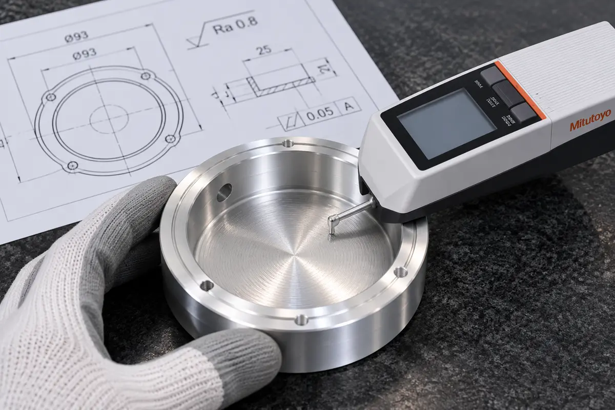
Choose an instrument that can resolve the specified parameter on the actual material and geometry. A contact stylus profilometer traces the surface with a diamond tip and calculates profile parameters such as Ra and Rz. Noncontact optical equipment may suit delicate, miniature, steep, or inaccessible areas, but engineering and quality teams should agree on the method and correlation basis before acceptance inspection. Visual inspection remains useful for scratches, coating defects, and cosmetic consistency, but it does not produce a numerical Ra or Rz result.
Match Trace Direction, Filter, and Evaluation Length
Measure in the specified direction and use the filter settings required by the governing standard or inspection plan. If the drawing does not state a direction, the inspector should normally traverse perpendicular to the dominant tool lay because a trace along the groove can read lower.
Record the parameter, result, units, instrument, stylus tip, cutoff or filter, evaluation length, and trace direction when those details affect interpretation. Calibration status and an appropriate roughness reference standard support traceability.
Define Inspection Locations, Sampling, and Acceptance
Name the functional zones, number of traces, lot sampling, and acceptance rule before inspection begins. A single reading at an accessible location may miss variation across a seal track, broad face, or multi-operation surface.
The drawing or quality agreement should also define how the inspector applies the limit. Under the applicable ISO rules, the 16% rule and a max rule represent different acceptance approaches. If the drawing states “Ra 0.8 max,” every measured trace covered by that requirement must remain below the threshold. The design authority or SQE should identify the applicable rule instead of leaving isolated readings open to interpretation.
Document Trace Data for Quality Records
Keep the roughness result tied to the part, surface, and drawing revision. A useful inspection record includes:
- part number, drawing revision, and lot or serial reference;
- instrument make, model, stylus tip radius, and calibration status;
- measured zone, trace direction, and filter settings;
- individual readings, acceptance limit, and disposition.
Rollyu Precision supports surface finish inspection with roughness testers and provides dimensional and inspection documentation for production projects. Engineering and sourcing teams can confirm the sampling rate, report format, and project-specific acceptance criteria during quotation.
Surface Roughness RFQ Checklist
Send the 2D drawing, 3D model, material specification, quantity, finish specification, and a surface-by-surface roughness schedule. The RFQ should identify the parameter and limit, units, governing standard, critical sealing zones, final inspection state, and requested CNC machining quality documentation.
Supporting information may include mating component drawings, seal or bearing specifications, approved appearance samples, and restricted measurement areas. These details help a machining partner check the process plan and inspection access before setting the price.
For engineering teams sourcing CNC machining parts, Rollyu Precision combines DFM review, surface finish inspection, and material traceability support. Ask the Rollyu team to flag unclear callouts, inaccessible measurement zones, or finish-stage conflicts before production.
Frequently Asked Questions
Can You Convert Ra Directly to Rz?
No fixed factor converts Ra to Rz for every machined surface. The relationship changes with profile shape, machining process, filtering, and the governing standard. An estimated ratio cannot replace the parameter required by the drawing, so inspect and report the specified parameter directly.
Can a Visual Finish Comparator Replace a Profilometer Reading?
A visual finish comparator can guide process setup, but it does not replace a numerical Ra or Rz reading when roughness is a functional acceptance requirement. Use a visual sample for color, gloss, pattern, and visible defects, then use the specified contact or optical method for profile texture.
How Do You Inspect Roughness Inside a Narrow Groove or Small Bore?
Agree on a small-hole stylus, a suitable noncontact method, a validated replica method, or a representative test feature before production. The selected method needs enough access and resolution for the specified parameter, and both inspection teams should document how its readings correlate with the acceptance requirement.
Should You Measure Roughness Before or After Anodizing or Coating?
Measure at the stage named by the functional requirement. Inspect the final condition when the coating or anodized layer forms the working surface. Add a pre-finish requirement when substrate preparation controls adhesion, and state the two stages separately because post-processing changes the measured texture.
