
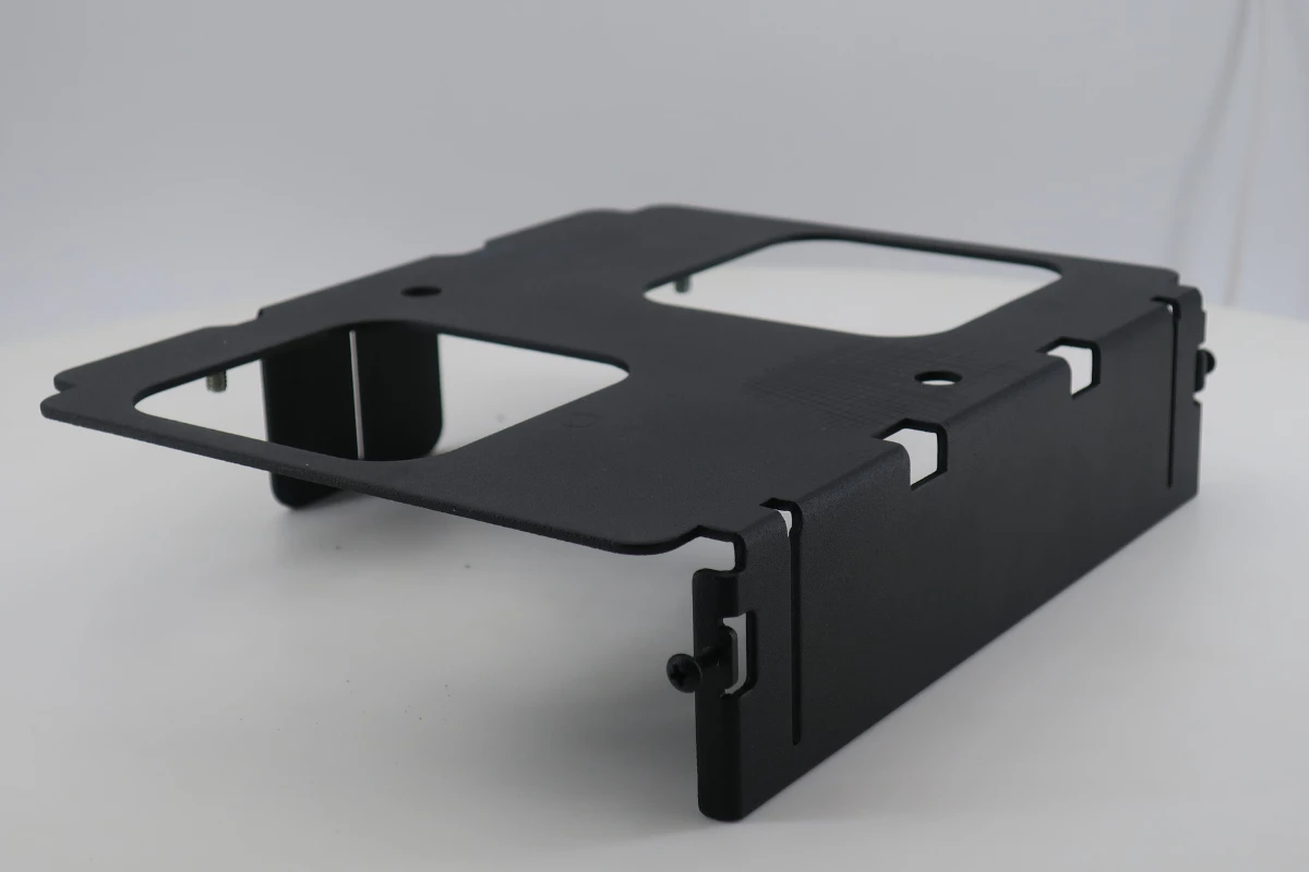

Specify sheet metal tolerances by feature and by the condition in which the part has to fit. A hole in a flat panel, a hole on a bent flange, and a completed assembly involve different dimensional relationships. One tight tolerance across the whole drawing can add work while leaving the important interface poorly defined. Start with the mounting or mating requirement, then identify the cut dimensions, bends, and finished surfaces that control it.
Match the Tolerance to the Feature
Size each tolerance to the feature’s job: what it locates, clears, or seals. A correctly sized hole can still sit in the wrong place, so hole diameter and hole location need separate requirements. A clearance opening and a locating hole in the same panel also deserve different limits, with the tightest values reserved for the features that control function.
| Feature | What the Requirement Controls | What to Identify on the Drawing |
|---|---|---|
| Cut hole or slot | Opening size for a fastener or mating feature | Finished size and any edge or coating condition that affects the opening |
| Holes on one face | The relationship between holes in a pattern | Hole locations relative to the chosen reference |
| Hole on a formed flange | Location after forming | Finished hole position relative to the mounting face or other functional reference |
| Bend angle | Orientation between faces | The angle and its inspection condition |
| Assembly interface | Fit between separately manufactured features | Mating dimensions, clearances, and finished condition |
| Sheet thickness | Stock input whose variation affects forming and hardware fit | Material grade and thickness; a gauge number does not set finished hole position |
Control Hole Position After Bending
Locate a formed feature from the interface it has to meet. The flat pattern supports fabrication, while the formed drawing describes the geometry the assembly uses.
Same-Plane and Across-Bend Dimensions
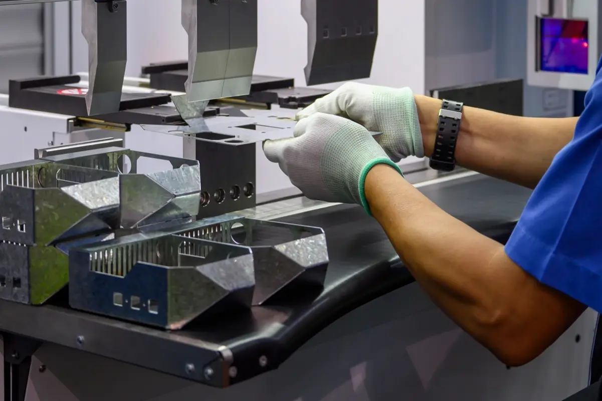
Holes cut on the same flat face keep the spacing set by the cutting process. A dimension that crosses a bend also depends on the formed geometry, and a hole close to the bend can distort during forming. On an L-bracket, for example, the base that bolts to the machine frame can serve as the reference for a hole on the upright leg. Dimension that formed relationship directly, because the hole-to-edge distance in the flat blank describes a different one. During sheet metal bending review, check the finished hole position together with the flange dimension and angle.
Angle Error at the Mounting Point
Even a small angle change can shift a feature substantially at a distance from the bend. Take a simplified rigid flange rotating about a fixed bend axis. A point 50 mm (1.97 in.) from that axis moves sideways by about 0.87 mm (0.034 in.) when the flange rotates 1° from its nominal position:
- Sideways shift = 50 mm × sin(1°) = 0.87 mm
The calculation isolates rotation and leaves out changes in bend radius, bend location, and hole position within the flange, so use it to judge how sensitive the mounting point is, not as a production tolerance. Springback shows why the angle needs control. WILA notes that sheet metal springs back slightly after bending, typically by about 2° to 4° on a 90° bend in mild or stainless steel, and the forming setup overbends to compensate. Left uncompensated, a 2° error would move the same 50 mm point by about 1.75 mm (0.069 in.). Specify the finished angle and feature position after springback.
Check Assembly Clearance at the Limits
Calculate clearance from the limiting finished dimensions, because nominal dimensions alone can hide interference or excessive movement. Suppose a bracket fits between two mounting rails. In this hypothetical one-dimensional check, the finished opening is 40.50 ±0.20 mm and the bracket’s finished outside width is 40.00 ±0.15 mm, a nominal total clearance of 0.50 mm. The smallest opening with the largest bracket leaves 40.30 − 40.15 = 0.15 mm, and the largest opening with the smallest bracket leaves 40.70 − 39.85 = 0.85 mm. These figures are total width gaps. Equal clearance on each side requires a centered bracket, and the calculation assumes both dimensions refer to the same checking location and finished state.
Decide whether the full 0.15–0.85 mm range meets the interface’s needs. If it does not, review the dimensions that drive this gap before tightening unrelated features. Positive width clearance still does not prove that the complete sheet metal assembly fits, since the hole pattern and flange orientation need their own checks through the actual mating features. Adding up the tolerances on every dimension in the drawing does not identify the variation in a particular interface.
Specify How the Finished Part Will Be Measured
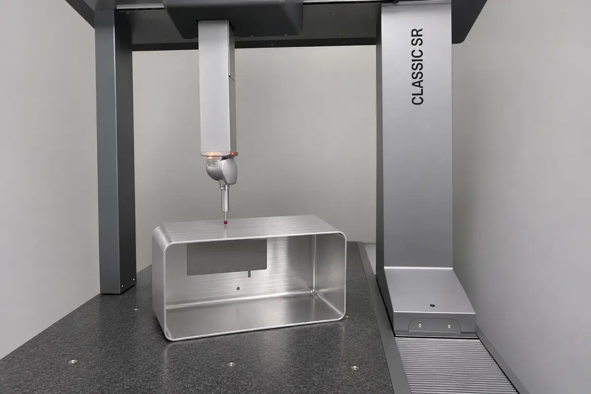
Put the measurement reference and part condition next to the tolerance, because a thin panel measured freely and the same panel held in a fixture can give different results. If a requirement applies in a restrained state, describe the locating surfaces, fixture contacts, and restraint. ISO 10579 sets the rules for verifying non-rigid parts this way. Then match the method to the feature: pin gauges for hole size, a coordinate measuring machine (CMM) for hole position and other spatial relationships, and height gauges for flange height against a reference surface.
State whether each critical dimension applies after forming, welding, or coating. Powder coating on both mating faces uses up part of their clearance, so settle masking and finished fit in the sheet metal finishing review. If the drawing already gives finished dimensions, do not add the coating allowance again.
Put the Tolerance Plan Into Production With Rollyu Precision
Rollyu Precision fabricates sheet metal parts by laser cutting, press-brake bending, and TIG, MIG, or spot welding, then deburrs, finishes, and inspects them.
DFM Review and Process Selection
Send the formed model and drawing with the material grade, thickness, finish, quantity, and critical mating dimensions. Mark the interfaces that control assembly and note what each one locates or clears, so Rollyu’s engineers can propose design for manufacturability (DFM) adjustments against those functional requirements.
For initial drawing discussions, Rollyu’s sheet metal handbook recommends ±0.005–±0.010 in. (about ±0.13–±0.25 mm) for hole-to-hole and hole-to-edge distances, ±0.010–±0.020 in. (about ±0.25–±0.51 mm) for flange height, and ±1° for bend angles. These are design references, and the production requirement is confirmed for the actual material, geometry, process, and inspection condition during project review.
Control Through Welding and Inspection
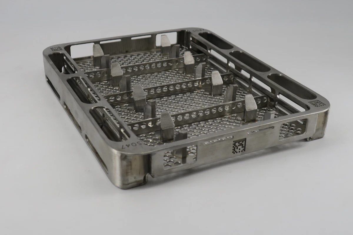
Welded parts need control beyond the cut dimensions. In Rollyu Precision’s dental sterilization tray case, 0.06 in. (about 1.52 mm) sheet carried 16 tack-welded locating pins whose position and perpendicularity set instrument location. The team fixed those relationships in dedicated tooling before welding, used a balanced welding sequence, controlled cooling and clamp release, and checked pin placement during setup and after welding. The sheet metal workflow also includes CMM inspection of critical dimensions, height and pin gauges where they suit the feature, and dimensional inspection reports on request. Name the reports you need when you request the quote.
Frequently Asked Questions
Does ISO 2768-1 Apply to Formed Sheet Metal Parts?
Yes. ISO 2768-1:1989 covers general linear and angular tolerances for dimensions without individual tolerance indications, on workpieces produced by metal removal or formed from sheet metal. ISO last confirmed this edition in 2022. Identify the applicable edition and tolerance class on the drawing, and give critical functional dimensions their own tolerances. The standard describes dimensional requirements and does not certify a supplier’s manufacturing capability.
Can Machining Improve a Critical Feature After Bending?
Yes, for selected features that need tighter control after forming. Rollyu’s sheet metal handbook lists post-machining as a separate process route, so ask the sheet metal fabrication team to include the specific feature and its finished requirement in the process review and quote. The machined feature’s tolerance does not carry over to the rest of the formed part.
Sources
- WILA, Tool Angle: Springback, its typical range on 90° bends in mild and stainless steel, and overbending to compensate.
- ISO 2768-1:1989: Scope of general linear and angular tolerances for machined and sheet-formed parts, last confirmed in 2022.
- ISO 10579:2010: Dimensioning and tolerancing of non-rigid parts that need restraint during verification.