


Start sheet metal box design with the finished internal space, the mounting interfaces, and the way the lid moves, then choose a shell layout the fabricator can cut and bend without losing those requirements. Wall thickness, corner joints, and lid flanges all take up space, so a box that looks large enough from the outside can still block the equipment inside or the path it takes out.
Start With the Finished Space and Interfaces
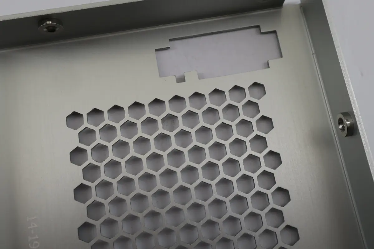
Define the usable internal space separately from the finished outside dimensions, because the box has to satisfy both: the equipment fits inside, and the enclosure fits its mounting location. As an illustration rather than a manufactured customer part, consider an enclosure with a base-mounted module, a connector opening in one wall, and a removable top lid. A layout like this needs space reserved for:
- The module and its mounting hardware, plus the path the module takes into the box, which inward-facing flanges can narrow.
- The connector body behind the panel, not just the cutout in the wall.
- Internal height, measured from the surface that supports the module to the lowest obstruction above it, such as a lid flange, screw end, or internal bracket.
- The outside envelope, including projecting lid edges, mounting flanges, and fastener heads wherever they approach surrounding equipment.
| Box Area | Functional Requirement | Design Focus | Manufacturing Confirmation |
|---|---|---|---|
| Internal cavity | Hold and install the module | Clear space after walls, hardware, and flanges are included | Finished cavity dimensions and assembly access |
| Mounting interface | Attach to the equipment frame | Mounting faces and hole positions | Formed dimensions relative to the mating frame |
| Connector opening | Accept the connector and its hardware | Cutout position, rear clearance, and nearby bend | Feature distortion and finished opening size |
| Top rim and corners | Support the lid without interference | Flange ends, corner gaps, and seam location | Bend access, corner treatment, and seating condition |
| Removable lid | Locate, fasten, and lift clear | Seating surfaces, mating clearance, and removal direction | Finished fit and access to the selected fasteners |
Choose How the Box Is Split and Formed
Choose the shell layout from the access the equipment needs and the bends required to create it. A folded tray keeps the base and walls in one part, while a U-shaped body with separate end panels moves the seams and changes how the enclosure goes together.
Folded Tray With a Separate Lid
A tray formed from one blank combines the base and four walls, which meet at corner seams that can stay open or receive a specified joint. In the example enclosure, this layout leaves the whole top free for installing the module. Inward top flanges give a flat lid surfaces to rest on, but they shrink the insertion opening and add bends near the corners, so compare the module’s installation envelope with the reduced opening before committing to the tray.
U-Shaped Body With End Panels
A U-shaped body forms the base and two opposing walls in one piece, and separate panels close the ends. Removing an end panel gives a second installation route when the module cannot pass through the top, but the extra panels bring joints, hardware, and fit dimensions of their own. When you compare sheet metal fabrication cost for the two layouts, include the bend sequence and seam work, since fewer pieces do not automatically mean less fabrication work.
Plan Bends Around Tool Access
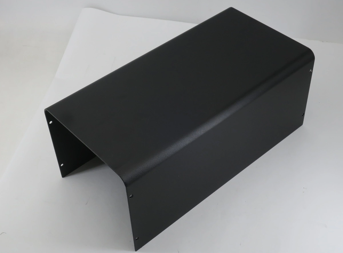
Confirm that each bend can still be formed after the bends before it. On a box, tall walls and return flanges swing up toward the press brake during the last bends, where they can hit the punch, die, tool holder, or the machine itself. WILA’s box-bending guidance names the press brake’s open height and the tool height as the main limits for deep boxes. For the tray, have the fabricator review the top flanges together with the wall bends, so the sequence leaves room to form the remaining walls and lift the part out of the tooling. A separate end panel or a revised flange arrangement may solve an access problem, as long as the box keeps its mounting and lid interfaces.
Confirm the material grade, condition, thickness, and intended inside radius during the sheet metal bending review. Keep connector cutouts and fastening holes out of the forming zone where practical, and when a feature has to sit near a bend, flag its finished shape and position for review against the actual tooling rather than relying on a universal setback.
Resolve Corners Before Finalizing the Lid
Choose the corner treatment together with the lid seating geometry, because both decide what happens at the top of each corner. A relief cut removes material where neighboring bends would otherwise interfere, and a corner seam defines how the formed wall edges meet. At each tray corner, trace the relief through the wall bend, check where it ends near the top flange, and confirm that the remaining material still supports the lid contact and any fastener. Where adjacent top flanges turn inward, their ends need clearance where they meet, since a corner that looks closed in CAD can still contain overlapping material. The seam type then sets what the lid has to clear.
- Open butt corner: Leaves a visible gap at the corner.
- Overlapping corner: Places one wall edge over the other, adding local thickness that can intrude into the path of a wraparound lid. Choose the overlap direction with that interface in mind.
- Welded corner: Specify the seam and its finished condition. Welding heat and cooling shrinkage can move the walls or rim, so check lid fit after the agreed welding and cleanup. Grinding a visible seam flush also adds work that an as-welded hidden seam may not need.
Design the Lid for Location, Clearance, and Removal
Define where the lid seats, what locates it sideways, and how it comes off the box before placing any screw holes. Those decisions set the mating geometry that the fasteners then have to respect.
Seating and Location
A flat lid can rest on the tray’s top flanges. Identify the supporting faces and the features that locate the lid horizontally: clearance holes only let screws pass, so use a defined locating feature when the lid needs precise positioning.
A lid with downturned edges, or skirt, fits around the outside of the walls. In the example enclosure, a skirt could hide the corner seams, but its inside surfaces then have to clear the box corners and any projecting hardware. Check the actual inside bend radii at the lid corners as well as its straight-wall dimensions, because a nominal rectangle does not describe the full mating shape.
Clearance After Forming and Finishing
Set lid clearance from the finished mating dimensions and their allowed variation. For a lid that slides over the box, the smallest allowed lid inside width has to clear the largest allowed box outside width, and the difference is the total width clearance, which splits into an equal gap per side only when the lid is centered. Run the same check on length, then inspect the corners, wall angle, and rim shape, since positive width clearance does not prevent a corner collision or a wall leaning into the removal path.
Powder coating adds material to every surface it covers, so coating on the box exterior and the lid interior both use up the gap between them. State whether drawing dimensions apply before or after finishing, and include the agreed coating buildup in the fit check without counting it twice when the dimensions already describe finished surfaces.
Fasteners and Removal Path
Place fasteners where a technician can tighten and release the lid with the equipment installed, leaving room for the driver body and its approach, plus access to hold a loose nut if the design uses one. For threaded inserts or self-clinching hardware, check the selected product’s requirements for sheet thickness, hole size, edge distance, and installation, and choose the sheet metal assembly method around the access that interface allows.
For the example’s lift-off lid, check the upward travel needed to clear the walls and any locating features. A connector, mounting bracket, or neighboring machine panel can block that movement even after every screw is out, so model the removal path with those surrounding parts in place, and confirm it on a fabricated sample when fit or service access is critical.
Prepare the Box and Lid for Manufacturing Review
Send the box and lid for review together. Their drawings need to agree on the assembled fit, the seam requirements, and the condition the parts are delivered in.
Models and Critical Finished Dimensions
Rollyu Precision offers engineering and design for manufacturability (DFM) review alongside custom manufacturing. For this enclosure, use that review to settle the shell split, bend access, corner treatment, and lid interface before the cutting geometry is released. Include the formed box and lid models, an assembly view, and an enclosure drawing that identifies:
- Material grade and condition, sheet thickness for each part, and matching drawing revisions
- Critical cavity dimensions, outside mounting dimensions, and connector locations
- Lid seating and locating features, mating clearances, and removable interfaces
- Corner seams, weld locations, visible faces, and the required surface condition
- Hardware references, quantities, and which dimensions apply after finishing
If the fabricator proposes a different radius or flat pattern, review the change in the assembled model against those critical finished dimensions before accepting it.
Fabrication and Delivery Scope
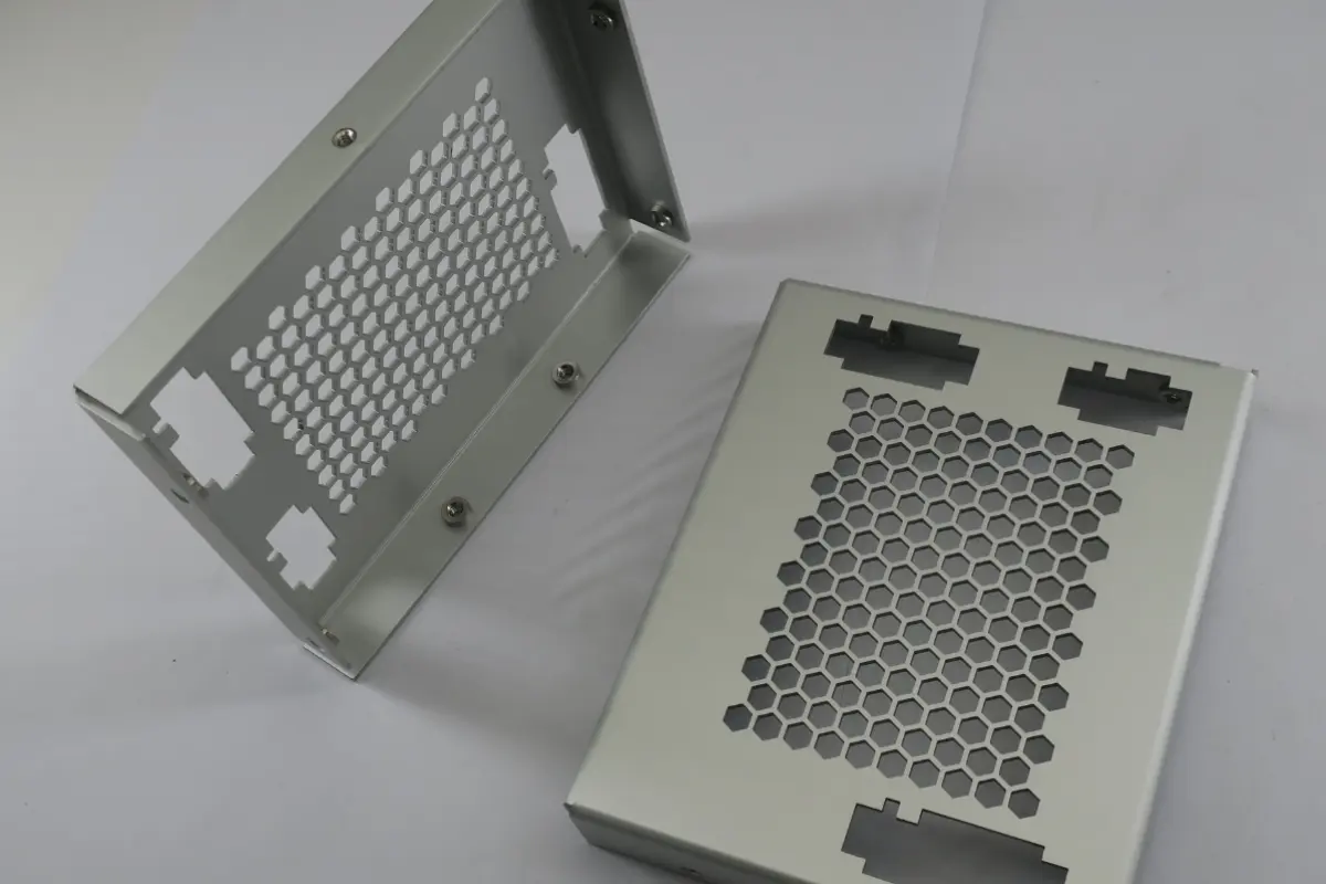
Rollyu’s sheet metal workflow covers laser cutting, press-brake bending, and TIG, MIG, and spot welding, followed by deburring, surface finishing, and dimensional inspection. Its powder-coated 5052-H32 aluminum enclosure shows that route on a finished housing, combining laser-cut aluminum sheet, press-brake forming, and a BK01 light-textured powder coat. Ask Rollyu to confirm the route for your specified material and geometry, including the finish, hardware installation, and lid-fit checks.
Define whether the order covers loose box and lid parts or an agreed assembled enclosure, and keep electrical integration and system-performance validation as separate project scopes. Send the models, critical dimensions, seam details, and surface requirements with the sheet metal fabrication quote request so manufacturing questions are settled against the same design.
Frequently Asked Questions
Can I Resize a Sheet Metal Box Template for a New Enclosure?
Yes, as a starting layout, but rebuild it around the selected sheet and hardware instead of scaling it. Scaling the whole model also scales thickness, bend radii, holes, and gaps, which may no longer match the manufacturing process or the purchased fasteners. Update the sheet metal rules, check the revised formed assembly, then regenerate the flat pattern.
Can the Lid Use a Different Sheet Thickness Than the Box?
Yes. Treat the lid as a separate sheet metal part with its own thickness and forming rules, and check its stiffness for the span and loading it will carry. Then review the changed corner geometry, fastening arrangement, and mating clearance, since the box’s sheet specification does not set a suitable lid thickness.