

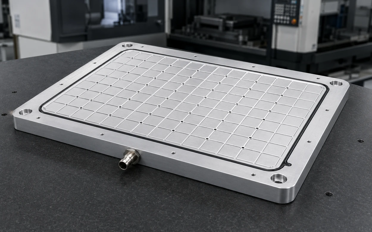
When a large aluminum plate must stay flat after pockets, vacuum channels and mounting patterns are machined, material stability often matters more than headline strength. That is where MIC6 aluminum and other cast tooling plates earn their place.
MIC6 is a proprietary precision cast aluminum tooling plate engineered for low residual stress, close thickness tolerance and consistent flatness. It is widely used for jigs, fixtures, machine bases, inspection plates, semiconductor tooling, vacuum chucks and automation components. Its value is not that it is the strongest aluminum available. Its value is that it helps a carefully planned machining process produce a stable, repeatable part.
This guide explains what MIC6 is, how it differs from 6061 and ATP-5, how to machine it, and which design details should be defined before requesting a quote.
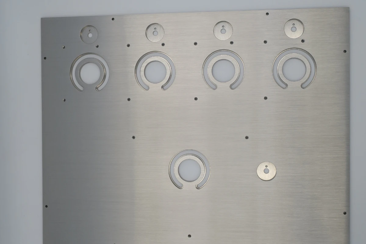
What Is MIC6 Aluminum?
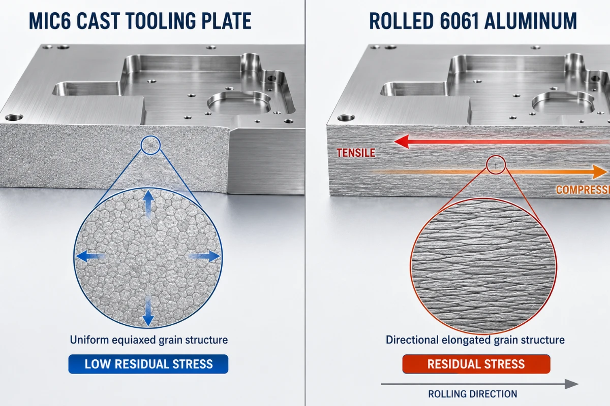
MIC6 is a continuously cast, thermally stabilized aluminum tooling plate supplied with precision-machined faces. The cast structure and stress-relief process are intended to minimize the internal stress that can move a part when material is removed. For large, flat components, that behavior can be more useful than the higher structural strength of a wrought alloy.
Because MIC6 is a proprietary plate product rather than a generic alloy designation, engineering drawings should specify the product name, thickness, required certification and any approved equivalent. Do not assume that every “cast aluminum plate” has identical mechanical properties, porosity limits, thickness tolerance or surface finish.
Why cast tooling plate behaves differently from wrought plate
Rolled 6061 plate gains useful strength from alloy chemistry, heat treatment and controlled working. Those processes can also leave residual stress through the thickness. Deep, one-sided machining may unbalance that stress and create bow or twist. A stress-relieved cast tooling plate starts with a more uniform granular structure and is designed specifically to reduce that movement.
| Design takeaway
Choose MIC6 when the primary risk is distortion of a broad, precision surface. Choose 6061 when structural strength, welding or general-purpose performance carries more weight. |
Key MIC6 Aluminum Properties
Published values should be treated as typical rather than guaranteed design allowables unless the purchase specification states otherwise. The following figures provide a practical reference for material selection.
| Property | Typical MIC6 value | Design meaning |
| Density | 2.70 g/cm³ | Lightweight relative to steel; similar to common aluminum alloys |
| Ultimate tensile strength | 165 MPa / 23.9 ksi | Lower than 6061-T6; not a strength-first plate |
| Yield strength | 105 MPa / 15.2 ksi | Confirm loads, joints and safety factors |
| Elastic modulus | 71 GPa / 10.3 Msi | Stiffness is similar to other aluminum alloys |
| Elongation | 3% | Limited ductility compared with common wrought products |
| Brinell hardness | 65 HB | Machines readily but threads need sound design |
| Thermal conductivity | 142 W/m·K | Useful for thermal plates and heat-spreading fixtures |
| Machined-face finish | Typically about 20 µin | May reduce initial face-machining, but not a substitute for final functional finishing |
Thickness tolerance and flatness depend on thickness, plate dimensions and supplier specification. A commonly published MIC6 thickness tolerance is ±0.005 in, while flatness limits vary by gauge. Always review the current material certificate and the actual cut size rather than transferring a catalog number directly to the finished-part drawing.
Flatness and thickness consistency
Precision-machined plate faces give the machinist a reliable starting stock surface. For fixture plates and machine bases, that consistency can reduce the amount of facing required and preserve more stock for critical features. Finished-part flatness, however, is still determined by part geometry, machining sequence, workholding, temperature and inspection method.
Low residual stress and dimensional stability
MIC6 is selected when the part includes broad pockets, counterbores, vacuum grooves or asymmetric material removal. Low residual stress reduces one major source of movement, but it does not eliminate deflection from clamping, cutting heat or a thin final section. Stability is a system-level result, not a material-only guarantee.
Why Use MIC6 for CNC Machining?
Reduced distortion in large-area machining
Large plates behave differently from compact blocks. A shallow bow that seems minor in raw stock can consume a flatness tolerance after unclamping. MIC6 helps reduce this risk, especially when the design needs a large sealing face, a precision mounting plane or a dense feature pattern that must remain coplanar.
Machine-ready surfaces and less stock removal
The supplied faces are already machined to a controlled finish and thickness. If the design allows one or both stock faces to remain, the process may require fewer facing passes, less tool time and less material removal. The drawing should explicitly identify whether the original plate face is acceptable on a functional surface.
Predictable chip formation
MIC6 is described by its manufacturer as free-cutting and capable of producing small, uniform chips in high-speed operations. In practice, sharp aluminum-specific tools, adequate flute space and effective chip evacuation help maintain edge quality and prevent recutting.
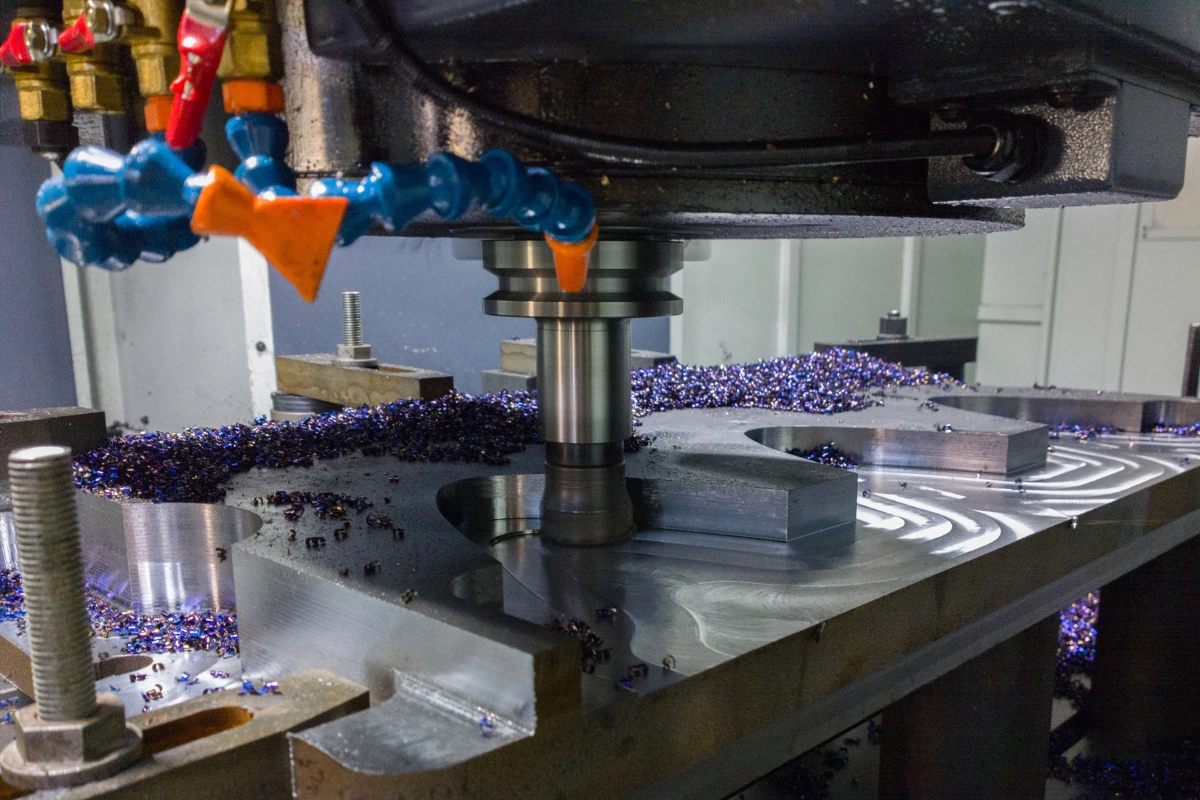
How to Machine MIC6 Aluminum
Plan stock orientation and datums
Before roughing, map the functional faces, primary datum and stock-face condition. Avoid removing most of the material from one side while the opposite face remains heavily constrained. If both sides require machining, use a balanced sequence and allow the part to relax between major operations.
Rough with balanced material removal
Use light, distributed clamping and leave finishing allowance on critical faces. For a deep pocket, rough in stages rather than taking the wall and floor directly to size. Where possible, alternate sides or release and re-seat the part before final finishing.
Control heat and chips
Sharp, polished cutting edges reduce built-up edge. High-positive-rake end mills, sufficient flute volume and a toolpath that avoids packing chips into deep pockets are generally effective. Flood coolant, mist or air blast may be appropriate depending on the machine and cleanliness requirement. The goal is to prevent local heating and chip recutting, not simply to maximize spindle speed.
Finish critical faces after relaxation
Leave a light, uniform finish allowance on flatness-critical surfaces. After roughing, unclamp or re-fixture the part so any movement is not locked into the final cut. Finish the primary datum first, then establish the remaining features from that datum.
Drill and tap with thread life in mind
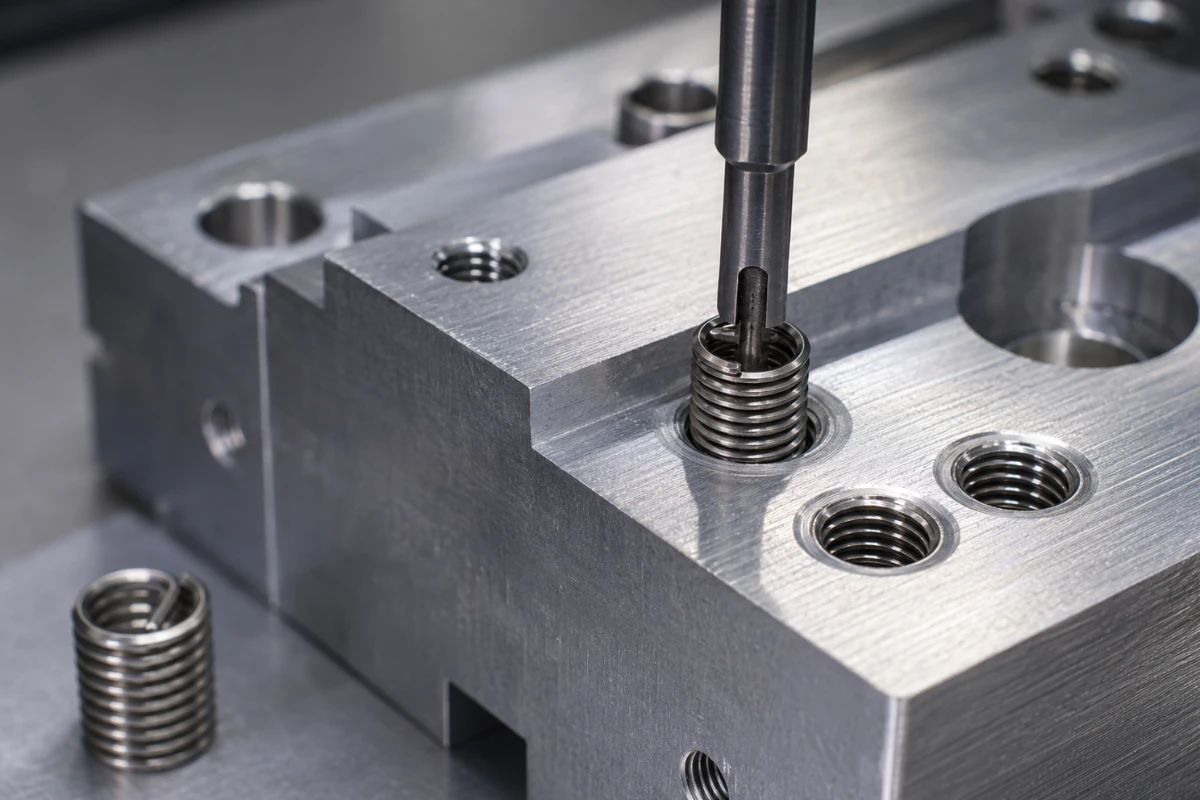
MIC6 can be drilled and tapped cleanly, but its relatively modest strength and ductility mean that short thread engagement or repeated assembly can damage internal threads. Use adequate engagement, avoid aggressive countersinks at thin edges, and consider key-locking, wire or solid threaded inserts for serviceable joints.
Inspect in a controlled state
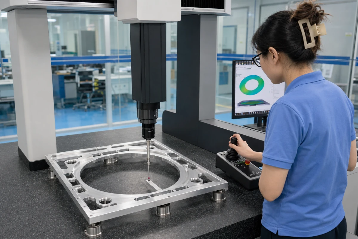
Flatness is sensitive to support points, clamping and temperature. Define the inspection condition: free state or restrained, support pattern, measurement method and temperature. A surface plate with indicator mapping may suit broad surfaces; CMM inspection is useful when flatness must be related to hole locations, bores or perpendicular datums.
| Quoting tip
For a large plate, specify finished thickness, flatness, parallelism, datum scheme and free-state inspection condition. A generic ±0.01 mm title-block tolerance does not communicate the functional requirement. |
MIC6 vs 6061 vs ATP-5
There is no universal “best” aluminum plate. The right choice follows the dominant engineering requirement.
| Material | Best suited to | Key advantages | Main cautions |
| MIC6 cast tooling plate | Stable fixtures, tooling plates, machine bases, optical and inspection platforms | Very low residual stress; precision-machined faces; predictable flatness and thickness | Lower strength and elongation than 6061-T6; cosmetic anodizing may be less uniform |
| 6061-T651 plate | Structural brackets, frames, welded assemblies and general-purpose machined parts | Higher strength; broad availability; weldable; familiar finishing options | Deep or asymmetric machining can release residual stress; usually needs more stock preparation |
| ATP-5 cast tooling plate | Vacuum/pressure tooling, corrosion-sensitive fixtures, welded tooling and large plates | 5083-based; stress relieved; strong corrosion resistance; supplier states vacuum/pressure integrity | Availability and product specifications vary by region; verify approved equivalent and certificates |
MIC6 aluminum vs 6061
Use MIC6 when flatness and post-machining stability are the controlling requirements. Use 6061-T651 when the component carries significant load, needs a welded joint or requires the well-established structural properties of a wrought heat-treated alloy. In a mixed assembly, a MIC6 baseplate and 6061 brackets can be a sensible combination.
MIC6 vs ATP-5 tooling plate
Both products are cast, stress-relieved tooling plates. ATP-5 is published as a 5083-based plate with higher tensile strength and elongation, strong corrosion resistance, weldability and guaranteed vacuum/pressure integrity from its manufacturer. MIC6 has extensive market recognition and a long history in precision tooling. Select by certified properties, thickness range, surface condition, availability, leak requirement and customer approval—not by brand familiarity alone.
Best Applications for MIC6 Tooling Plate
Vacuum chucks and fixture plates
MIC6 is frequently used for vacuum tables and workholding plates because it can support broad, flat sealing surfaces and dense hole patterns. If the design depends on leakage performance through the plate, define the allowable leak rate and test method; do not assume every plate is automatically vacuum-tight.
Semiconductor and inspection equipment
Stable baseplates, nests and metrology fixtures benefit from controlled flatness and repeatable feature location. Electrical isolation, cleanliness, coating and particle-generation requirements should be included in the drawing package.
Robotics and motion-control bases
Encoder mounts, linear-stage bases and actuator fixtures often need a large reference plane with accurately located bores. MIC6 works well for stationary precision structures, while high-load arms and dynamic brackets may be better suited to 6061 or 7075 after stiffness and fatigue analysis.
Photonics and optical platforms
Optical benches and alignment fixtures require stable datum surfaces and repeatable hole patterns. Thermal gradients, black anodizing, helicoil or key-locking inserts and stray-light control are common design considerations.
Medical and life-science fixtures
Diagnostic instrument fixtures and laboratory automation plates may prioritize cleanliness, dimensional consistency and frequent assembly. Define coating chemistry, cleanability, lot traceability and restricted-substance requirements early.
Molds, platens and thermal tooling
The plate’s thermal conductivity and stability are useful for low-load molds, heating plates and test fixtures. For high pressure, high wear or elevated temperature, verify strength, creep, surface hardness and expected service life before choosing MIC6.
Design Rules for MIC6 Machined Parts
Design for stability, not maximum load
MIC6 should not be treated as a direct mechanical substitute for 6061-T6 or 7075-T6. Calculate bearing, thread, bending and fastener loads using certified properties and suitable safety factors. Increase section thickness, add inserts or choose a stronger alloy when the load path demands it.
Preserve balanced sections
Large differences in wall thickness can create thermal and machining distortion even in stable stock. Use symmetric pockets where possible, maintain generous radii at pocket corners and avoid leaving a very thin membrane across a large unsupported area.
Specify threads deliberately
- Use sufficient thread engagement for the fastener size and expected preload.
- Add threaded inserts where assemblies will be serviced repeatedly.
- Keep tapped holes away from thin edges and pocket walls.
- Identify insert type, installation depth and locking method on the drawing.
- Mask or plug threads when coating buildup could interfere with fit.
Define functional surfaces
Not every face needs the same finish or tolerance. Mark sealing faces, bearing seats, rail-mounting surfaces and optical datums. Relax nonfunctional surfaces so machining effort is concentrated where it improves assembly performance.
Surface Finishing Options
As-machined and precision-finished surfaces
As-machined MIC6 provides a practical industrial appearance and preserves dimensional predictability. Critical faces can be finish milled, ground or lapped when the specification justifies the added process. Surface roughness and flatness are separate requirements and should be called out independently.
Anodizing
MIC6 can be anodized, including black anodizing for glare control, but cast alloy chemistry and microstructure can produce a darker, grayer or less uniform cosmetic result than 6061. If appearance matters, approve a sample or color range. Dimensionally critical bores, threads and sealing faces may need masking or post-coating machining.
Chemical conversion, paint and powder coating
Chemical conversion coatings can support corrosion protection and electrical grounding strategies. Paint and powder coating offer color and environmental protection but add more thickness than conversion coating. Define masked surfaces and coating allowance in the CAD and drawing.
What Drives MIC6 Machining Cost?
Raw plate price is only one part of the finished-part cost. The larger drivers are often material removal, setup count, flatness control and inspection.
- Plate size, thickness and certified material availability
- Percentage of stock removed and whether both sides are machined
- Deep pockets, thin webs, vacuum channels and cross-drilled passages
- Flatness, parallelism and positional tolerances
- Threaded inserts, dowel bores and precision counterbores
- Surface treatment, masking and post-coating rework
- CMM reports, surface mapping, leak testing and material traceability
A design that retains a qualified stock face and uses realistic tolerances can cost less than a nominally simpler part that requires repeated stress-relief cycles, re-fixturing and full-surface inspection.
How Rollyu Precision Supports MIC6 Aluminum Projects
Rollyu Precision can review your model and drawing as a manufacturing system rather than treating each feature independently. The review should align material selection, stock condition, workholding, machining sequence, finishing and inspection with the surfaces that control assembly performance.
| Project stage | Rollyu support |
| DFM and material review | Compare MIC6, ATP-5 and 6061 against strength, flatness, corrosion, welding and finishing requirements |
| Process planning | Plan balanced roughing, relaxation, re-fixturing and final datum finishing |
| Precision machining | Machine large faces, pockets, hole patterns, bores, threads and insert features |
| Surface finishing | Coordinate anodizing, conversion coating, paint or other specified finishes with masking requirements |
| Quality control | Inspect dimensions, position, flatness and parallelism using the method defined for the part
|
| Best RFQ package
Send a STEP model and a controlled PDF drawing. Identify the approved plate product, finished thickness, datum scheme, critical flatness/parallelism, coating, inserts, inspection condition, quantity and delivery target. |
Frequently Asked Questions
Is MIC6 aluminum the same as 6061?
No. MIC6 is a proprietary cast tooling plate designed around flatness and low residual stress. 6061 is a wrought, heat-treatable alloy commonly selected for higher structural strength, welding and general-purpose components.
Is MIC6 stronger than 6061-T6?
No. Published MIC6 tensile and yield values are substantially lower than typical 6061-T6/T651 values. MIC6 should be selected for stability and precision plate behavior, not as a strength upgrade.
Does MIC6 warp during machining?
It generally moves less than conventional wrought plate because it is stress relieved, but it can still distort from unbalanced stock removal, thin geometry, clamping force or heat. Balanced machining and free-state inspection remain important.
Can MIC6 be anodized?
Yes. Functional anodizing is common, but color may be less uniform than on 6061. Approve a sample or acceptable color range for cosmetic parts, and account for coating buildup on bores and threads.
Can MIC6 be welded?
Welding may be possible for some noncritical tooling, but MIC6 is not normally the first choice for a welded structural assembly. If welding is central to the design, compare ATP-5 or 6061 and qualify the procedure.
Is MIC6 suitable for vacuum chucks?
It is widely used for vacuum fixtures because of its flatness and stability. If leakage through the plate is critical, specify a leak-rate requirement and test method or select a product with a documented vacuum/pressure integrity guarantee.
Can MIC6 hold tight tolerances?
Yes, when the feature size, plate geometry, machining sequence, temperature and inspection method support the requirement. Tight local hole or bore tolerances are different from tight flatness across a large plate, so both must be quoted separately.
What should I send for a MIC6 machining quote?
Send the 3D CAD file, 2D drawing, plate grade and thickness, critical datums, flatness and parallelism, surface finish, coating, inserts, quantity, inspection documentation and delivery requirement.
Ready to Quote Your MIC6 Aluminum Part?
| TURN A STABLE PLATE INTO A STABLE ASSEMBLY
Send Rollyu Precision your CAD model, drawing, material requirement and critical flatness targets. Our team can review machinability, tolerances, finishing and inspection before production. REQUEST A QUOTE → www.rollyu.com |
