

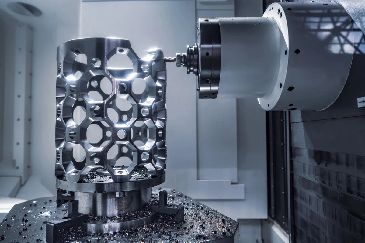
Machining 6061 aluminum is often the starting point for engineers who need lightweight, corrosion-resistant, and cost-effective CNC parts. The alloy offers a practical balance of strength, machinability, availability, weldability, and anodizing response. It is widely used for optical mounts, motion-stage housings, robotic frames, medical-equipment housings, fixtures, brackets, and structural components.
However, choosing 6061 does not eliminate manufacturing risk. The material temper, stock form, wall thickness, pocket geometry, tolerance scheme, clamping method, and surface finish can all affect the final result. A thick 6061-T651 plate with shallow features behaves differently from a thin-walled 6061-T6 housing machined from extruded stock.
What Is 6061 Aluminum
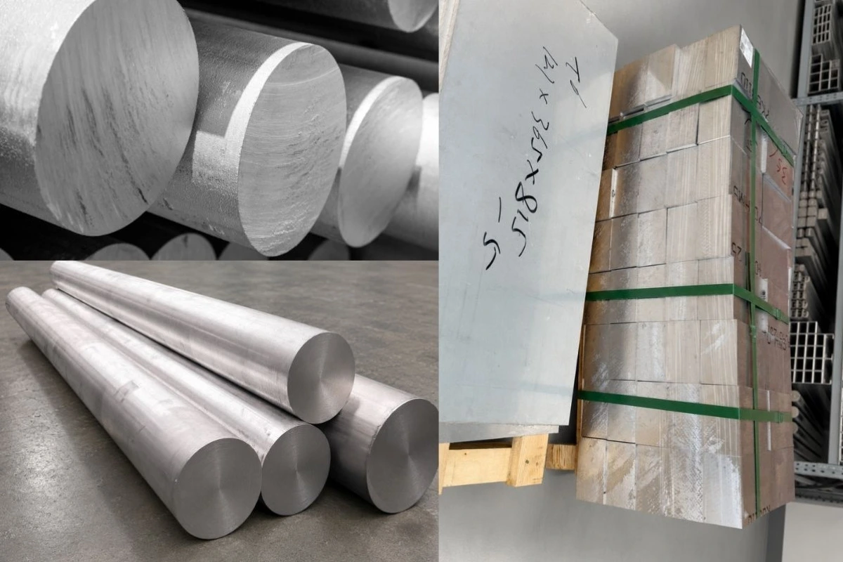
6061 is a heat-treatable wrought aluminum alloy whose main alloying elements are magnesium and silicon. It belongs to the 6xxx series and is supplied globally as plate, sheet, bar, tube, extrusion, and forged stock.
Depending on the standard and market, the same alloy family may appear as:
- AA 6061 or UNS A96061
- EN AW-6061 or EN AW-AlMg1SiCu
- A6061 under JIS conventions
- AlMg1SiCu or material number 3.3211 in older German references
The drawing and purchase order should identify not only “6061,” but also the required temper and applicable material specification. Writing only “aluminum” or “6061” leaves uncertainty about strength, hardness, dimensional stability, and certification requirements.
Why Engineers Choose 6061 for CNC Parts
6061 is popular because it provides a useful combination of:
- Moderate-to-high strength after heat treatment
- Low density of approximately 2.70 g/cm³
- Good corrosion resistance in many normal industrial environments
- Reliable milling, drilling, boring, tapping, and turning performance
- Good response to Type II and Type III anodizing
- Broad availability in standard stock sizes
- Better weldability than many high-strength aluminum alloys
- Competitive material and machining cost
6061 is not the strongest aluminum alloy, the freest-cutting turning alloy, or the most dimensionally stable tooling plate. Its advantage is balance. For many general precision components, that balance reduces sourcing risk and simplifies the route from prototype to production.
6061-T6 vs. 6061-T651: Which Temper Should You Machine?
The temper is one of the most important decisions when machining 6061 aluminum.
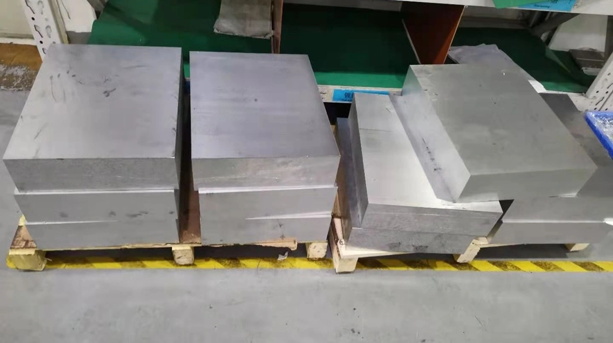
6061-T6
6061-T6 is solution heat-treated and artificially aged. It is widely available in bar, extrusion, tube, and many other stock forms. It is a practical choice for:
- Turned shafts, spacers, adapters, and fittings
- Extrusion-based frames and rails
- Brackets and general structural parts
- Components with moderate material removal
- Welded assemblies where post-weld strength is evaluated separately
T6 stock can machine well, but residual stresses from rolling, extrusion, quenching, or prior processing may become visible as material is removed. Thin walls, asymmetric pockets, and heavy machining on one side can allow a part to move after unclamping.
6061-T651
6061-T651 is solution heat-treated, stress relieved by controlled stretching, and artificially aged. It is commonly associated with plate. The stress-relief step makes T651 a preferred starting condition for many milled parts that require:
- Better dimensional stability during heavy material removal
- Large flat machined surfaces
- Deep or asymmetric pockets
- Tight positional relationships across a broad plate
- Reduced movement between roughing and finishing
- More predictable inspection after unclamping
T651 does not make distortion impossible. Poor stock selection, excessive clamping force, heat buildup, unbalanced machining, or unrealistic wall geometry can still create movement. It simply provides a more stable starting point for many plate-machined components.
Practical T6 and T651 Selection Table
| Part requirement | Recommended starting point | Engineering reason |
| Turned parts from bar | 6061-T6 | Broad bar availability and efficient turning |
| General brackets and housings | 6061-T6 or T651 | Select according to stock form and removal ratio |
| Large milled plate or base | 6061-T651 | Better starting stability for broad machined surfaces |
| Deep-pocket housing | 6061-T651 | Helps reduce movement as residual stress is released |
| Thin-walled enclosure | T651 plate where practical | Stability still requires staged and balanced machining |
| Extruded frame or profile | 6061-T6 | Readily available as extrusion; verify straightness and datum strategy |
| Part requiring bending before final machining | T4 or another formable condition may be considered | T6 is less formable; final properties and heat treatment need review |
How Is 6061-T6 Aluminum Machined?
The most suitable process depends on part geometry, annual quantity, tolerance, and stock form. Rollyu Precision typically evaluates the complete manufacturing route rather than selecting a machine from the material name alone.
CNC Milling of 6061 Aluminum
Three-axis milling efficiently produces plates, brackets, covers, fixtures, and housings. Four-axis and five-axis machining can reduce refixturing for parts with features on multiple faces, compound angles, optical interfaces, or tightly related datums.
For milling, the process plan should address:
- Tool access to deep pockets and internal corners
- Wall support during roughing
- Chip evacuation from enclosed cavities
- Datum transfer between setups
- Flatness after the part is released from the fixture
- Finishing stock on sealing, bearing, and optical mounting surfaces
A five-axis machine can improve access and reduce setups, but it cannot compensate for an unstable design or residual stress. The material-removal sequence remains critical.
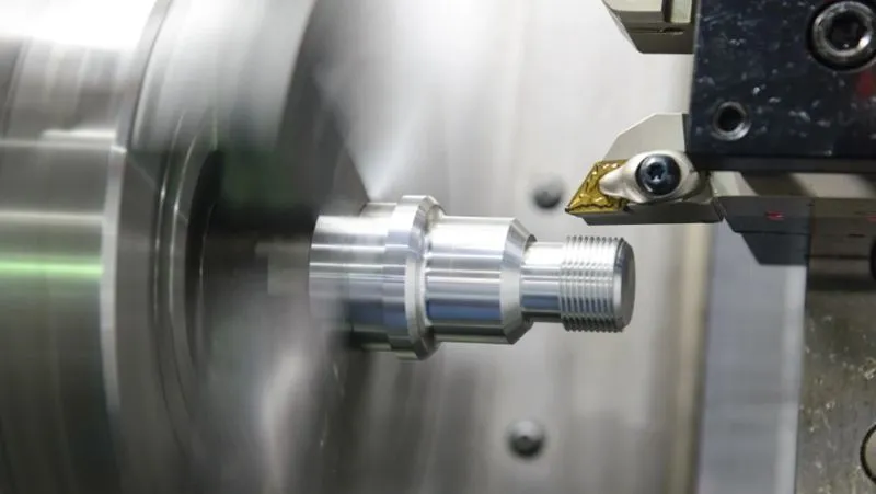
CNC Turning and Mill-Turn Machining
6061-T6 bar is suitable for shafts, bushings, threaded connectors, spacers, adapters, nozzles, and custom fasteners. Live tooling can add cross holes, wrench flats, slots, and off-axis features without transferring the component to a separate machining center.
For production turning, engineers should consider:
- Diameter-to-length ratio
- Thread class and gauge method
- Concentricity between stepped diameters
- Burrs at cross holes and thread runouts
- Jaw marks on cosmetic surfaces
- Part-off witness marks
- Whether bar stock or near-net extrusion provides the better yield
If maximum cycle-time efficiency is more important than the general-purpose properties of 6061, free-machining alloys such as 2011 or 6262 may also deserve review. The final choice should still account for strength, corrosion resistance, anodizing, compliance, and material availability.
Drilling, Boring, Reaming, and Tapping
6061 generally drills and taps cleanly, but critical holes require more than a nominal drill size. Bearing seats, dowel holes, optical bores, and sealing diameters may need boring or reaming after rough machining.
Good drawing practice includes:
- Identifying fit rather than specifying an unnecessarily tight bilateral tolerance
- Providing thread class and thread depth
- Separating full thread depth from drilled depth
- Calling out countersinks and spotfaces clearly
- Identifying holes that must be protected during anodizing
- Defining whether dimensions apply before or after surface treatment
What Makes Machining 6061 Aluminum Difficult?
6061 is considered machinable, but several predictable problems can still affect precision parts.
Built-Up Edge and Aluminum Welding to the Tool
Aluminum can adhere to a cutting edge when tool geometry, lubrication, chip evacuation, or cutting conditions are unsuitable. The resulting built-up edge can damage the surface, alter dimensions, and create burrs.
Typical controls include:
- Sharp tools with geometry intended for aluminum
- Polished flutes or suitable aluminum-cutting tools
- Adequate coolant or minimum-quantity lubrication where appropriate
- Reliable air or coolant delivery to clear chips
- Cutting parameters matched to tool diameter, engagement, rigidity, and spindle capability
Universal speed-and-feed values should not be copied directly from a generic article. The correct parameters depend on tool manufacturer data, toolpath engagement, machine rigidity, holder runout, coolant strategy, and the required finish.
Burr Formation
Burrs commonly appear at drilled-hole exits, milled edges, intersecting holes, slots, and thread runouts. A burr that appears minor on a bracket can interfere with an O-ring, cable path, bearing, optical element, or assembly datum.
The process may combine controlled edge breaks, chamfer milling, manual deburring, brushing, tumbling, or specialized deburring methods. Critical edges and “must remain sharp” features should be identified on the drawing rather than left to interpretation.
Thin-Wall Deflection
Thin walls can deflect under cutting pressure or clamping load. After the tool or fixture is removed, the feature may spring away from its inspected position.
Risk increases with:
- Tall walls with limited support
- Deep pockets and large unsupported floors
- Abrupt thickness transitions
- Heavy machining concentrated on one side
- Very tight profile or flatness requirements
The manufacturing plan may use staged roughing, temporary support material, soft jaws, vacuum fixtures, low-force workholding, balanced toolpaths, and multiple finishing passes.
Distortion After Material Removal
Distortion is not simply a machine-accuracy problem. It can result from residual stress in the stock, unbalanced material removal, local heat, or clamping force.
A robust plan may include:
- Selecting a stable stock form, often T651 plate for heavily milled parts.
- Roughing both sides in a balanced sequence.
- Leaving controlled finishing allowance.
- Releasing and reclamping the part before final machining.
- Allowing stabilization between major operations when needed.
- Inspecting the part in a free state using a defined datum scheme.
Stress-relief heat treatment should not be added casually after the drawing material condition has been specified. Thermal processing can change mechanical properties, dimensions, and certification status. Any additional heat-treatment route should be reviewed with the engineer and material supplier.
Designing 6061-T6 Precision Machined Parts
Design decisions made before quoting often have a greater effect on cost and yield than small changes in cutting speed.
Use Functional Tolerances
Apply tight tolerances to interfaces that control fit, alignment, sealing, motion, or optical performance. Use more economical general tolerances on noncritical surfaces.
This allows the supplier to focus process capability and inspection time where they affect function. It also reduces unnecessary rework caused by tolerances that do not improve the assembly.
Avoid Unnecessarily Deep, Narrow Pockets
Long-reach tools are less rigid and can create chatter, tapered walls, longer cycle times, and poor chip evacuation. Where possible:
- Increase internal corner radii
- Reduce pocket depth
- Open one side for tool access
- Divide one extreme cavity into machinable levels
- Match corner radii to practical cutter sizes
Design Threads for Manufacturing and Finishing
Specify thread standard, size, class, depth, and inspection expectation. Include a practical thread relief where needed and allow room for tool runout.
If the part will be anodized, state whether threads are to be masked, plugged, chased after finishing, or accepted with coating. Anodic buildup can affect small threads and precision fits.
Control Cosmetic Requirements
“No scratches” is difficult to interpret and inspect. A better specification identifies:
- Cosmetic surfaces and viewing direction
- Allowed handling marks
- Surface preparation such as bead blasting
- Anodizing type and color
- Gloss or texture expectation
- Color-match reference and acceptable variation
- Areas where rack or contact marks are permitted
Surface Finishes for Machined 6061 Aluminum
6061 responds well to several common finishes. The correct choice depends on corrosion, wear, electrical, cosmetic, and dimensional requirements.
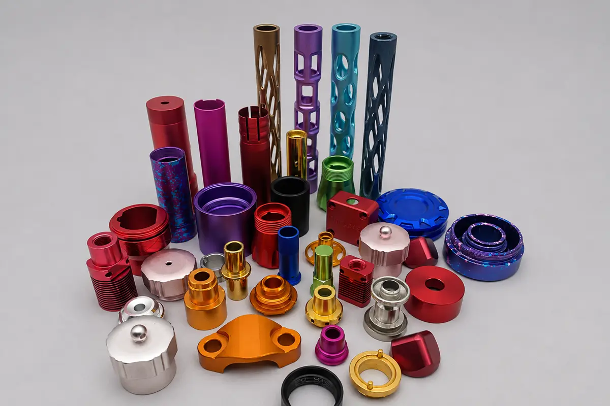
Type II Anodizing
Type II anodizing is commonly selected for corrosion resistance and cosmetic color. Clear, black, blue, red, gold, and other colors may be available, but the final appearance depends on alloy, temper, surface preparation, film thickness, dye, sealing, and lot conditions.
For matched cosmetic assemblies, process all visible components in the same controlled batch where practical and approve a physical color range instead of relying only on a screen image or color name.
Type III Hard Anodizing
Type III hard anodizing is chosen when wear resistance, surface hardness, or electrical insulation is more important. Its greater coating thickness has a more significant dimensional effect than decorative anodizing.
Engineering drawings should identify:
- Critical bores, bearing fits, and sliding interfaces
- Threads and grounding points
- Masked sealing faces
- Whether the stated size applies before or after anodizing
- Allowed coating thickness and any post-finish inspection
Bead Blasting Before Anodizing
Bead blasting can create a uniform matte appearance and reduce the visibility of minor machining marks. It does not correct poor machining, deep scratches, dents, or waviness. Excessive blasting can soften sharp edges and alter very small features, so masking and process control may be required.
Chemical Conversion Coating
Chemical conversion coating, often called Chemfilm or chromate conversion coating, can improve corrosion protection and paint adhesion while having less dimensional effect than anodizing. It may be selected for electrical grounding areas, internal components, or parts that will be painted.
The drawing should state the required specification, class or type, and whether a hexavalent-chromium-free process is required.
How Does 6061 Compare with Other Aluminum Alloys?
| Alloy | Main advantage | Typical CNC application | Key limitation or watch point |
| 6061-T6/T651 | Balanced strength, machinability, corrosion resistance, availability, and finishing | Brackets, housings, frames, optical mounts, fixtures | Lower strength than 7075; distortion still needs process control |
| 7075-T6 | High strength-to-weight ratio | Highly loaded aerospace, robotics, and motion components | Higher cost, lower corrosion resistance, poor general weldability |
| 2024-T3/T351 | Strength and fatigue performance | Aerospace structures and mechanisms | Corrosion protection commonly requires more attention |
| 5052-H32 | Formability, welding, and corrosion resistance | Bent sheet-metal covers, panels, and enclosures | Not normally the first choice for heavily machined high-strength features |
| 6063-T5/T6 | Extrusion quality and cosmetic anodizing | Profiles, heat sinks, frames, and visible trim | Lower strength than 6061 in many common tempers |
| MIC-6 cast tooling plate | Flatness and low residual stress | Equipment bases, fixtures, tooling plates, inspection nests | Different strength and finishing behavior; not a direct replacement for structural 6061 |
For a broader comparison of 6061, 7075, 2024, 5052, and other types of aluminum for CNC machining, review our aluminum alloy selection guide.
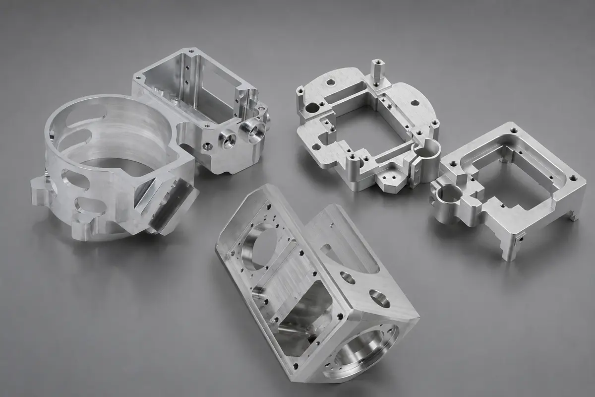
Typical 6061-T6 Precision Machined Parts by Industry
Photonics and Quantum Instrumentation
6061 is frequently used for:
- Lens holders and lens clamps
- Laser mounts and optical bases
- Fiber holders
- Camera mounts
- Goniometer bases and plates
- Compact optical-bench structures
These components often require positional accuracy, stable datums, controlled black anodizing, protected threads, and clean assembly surfaces. For highly stability-sensitive optical structures, the engineer should also evaluate thermal behavior, material symmetry, and whether another alloy or stress-relieved plate is more appropriate.
Robotics and Automation
Typical applications include:
- Robot brackets and lightweight frames
- Motor mounts
- Sensor housings
- Gripper components
- Joint covers
- End-effector plates
The primary benefits are low weight, straightforward machining, corrosion resistance, and the ability to integrate pockets, cable paths, mounting patterns, and alignment features in one component.
Motion Control
6061-T6 and T651 are used for:
- Linear-stage housings
- Bearing blocks
- Motor and encoder mounts
- Slides and carriage plates
- Structural bases
- Precision adjustment components
Motion-control parts need careful datum planning. Bearing bores, rail interfaces, motor pilots, and encoder surfaces should be related to functional datums rather than to arbitrary outside faces.
Medical and Life-Science Equipment
6061 is suitable for many nonimplantable equipment components, including:
- Diagnostic-equipment housings
- Surgical-robot brackets
- Laboratory-instrument frames
- Imaging-system mounts
- Handles, covers, and equipment fixtures
Material choice and finish should reflect the actual cleaning chemicals, sterilization exposure, biocompatibility requirements, and regulatory classification. General-purpose 6061 should not automatically be assumed suitable for implant or direct patient-contact use.
Aerospace and Satellite Equipment
6061 may be selected for:
- Equipment brackets
- Optical and sensor housings
- Ground-support fixtures
- Lightweight frames
- Electronic enclosures
- Mechanism supports
For flight or space hardware, the drawing may require controlled material traceability, approved specifications, first-article inspection, special-process certification, cleanliness controls, and customer-approved suppliers. The alloy must be selected from the actual load case and environment rather than from a generic application list.
Prototype and Production Considerations
6061 is suitable for prototypes, bridge production, and repeat batches, but the cost driver changes with quantity.
Prototype Quantities
For prototypes, the primary cost drivers are programming, setup, fixturing, inspection planning, and one-time process development. Using standard 6061 stock and avoiding unnecessary special tooling can reduce lead time.
Low- and Medium-Volume Production
At repeat quantities, cost reduction may come from:
- Dedicated soft jaws or modular fixtures
- Combining operations on four-axis or five-axis equipment
- Optimized toolpaths and tool life
- Family fixtures for related components
- In-process probing
- Standardized deburring and finishing routes
- Inspection sampling supported by process capability
Repeat Orders
Stable repeat production requires revision control, controlled material sources, retained inspection methods, approved finish standards, and documented packaging. The lowest initial unit price is not always the lowest total cost if color variation, distorted parts, damaged cosmetic surfaces, or inconsistent threads interrupt assembly.
Quality Control for Machined 6061 Parts
Inspection should be planned from the drawing and part function. Depending on the component, verification may include:
- CMM inspection of datum-related features
- Optical or vision measurement
- Bore gauges, pin gauges, and thread gauges
- Surface-roughness measurement
- Flatness and parallelism checks
- Coating-thickness verification
- Cosmetic inspection under defined lighting
- Material certificates and special-process certificates
- First Article Inspection or dimensional reports
Dimensions should generally be inspected in the same condition in which the customer will use the part. If the drawing defines dimensions after anodizing, the inspection plan must account for the finished coating rather than report only pre-finish measurements.
RFQ Checklist for Machining 6061 Aluminum
To receive an accurate quote, send:
- 3D CAD file, preferably STEP
- Controlled 2D drawing
- Material and temper, such as 6061-T6 or 6061-T651
- Applicable material specification
- Quantity for prototype and production
- Critical dimensions, GD&T, and datum structure
- Surface roughness only where functionally required
- Anodizing or conversion-coating specification
- Masking, plugging, and grounding requirements
- Cosmetic surface definition
- Inspection report or First Article requirements
- Material and finish certification requirements
- Packaging and cleanliness requirements
- Target delivery schedule
If the temper, finish, or tolerance is uncertain, identify the functional requirement instead of guessing. A supplier can provide a more useful DFM recommendation when it understands the load, mating components, operating environment, and cosmetic expectation.
Why Source Machined 6061 Parts from Rollyu Precision?
Rollyu Precision supports custom 6061 aluminum components from prototype through repeat production using CNC milling, five-axis machining, turning, and coordinated surface finishing. Our engineering review focuses on material condition, datum strategy, tool access, distortion risk, anodizing allowance, inspection, and packaging before production begins.
Typical projects include precision housings, optical mounts, robot brackets, stage components, medical-equipment parts, equipment bases, and lightweight structural components.
Send your CAD files, drawing, quantity, application, and finish requirement for a manufacturability review and quotation.
Frequently Asked Questions About Machining 6061 Aluminum
Is 6061 aluminum easy to machine?
Yes. 6061 is generally considered a machinable aluminum alloy and works well for milling, turning, drilling, boring, and tapping. Sharp aluminum-cutting tools, reliable chip evacuation, appropriate lubrication, rigid workholding, and a stable material condition are still necessary for tight-tolerance parts.
What is the difference between 6061-T6 and 6061-T651?
Both conditions are solution heat-treated and artificially aged. T651 includes a controlled stress-relief step by stretching. For heavily milled plate components, 6061-T651 is often preferred because it provides a more stable starting condition and can reduce movement as material is removed.
Is 6061-T6 or 6061-T651 better for CNC machining?
Neither is universally better. T6 is widely used for bar, extrusion, tube, turned parts, and general components. T651 plate is often the better starting point for large milled surfaces, deep pockets, or parts with high material removal and demanding flatness.
What tolerances can be achieved when machining 6061 aluminum?
Achievable tolerance depends on feature size, geometry, wall thickness, datum scheme, surface finish, machine capability, fixture design, inspection method, and quantity. Tight tolerances should be assigned to functional features instead of applied to every dimension. Rollyu reviews the drawing before confirming capability.
Does 6061 aluminum warp during machining?
It can. Distortion may result from residual stress, asymmetric material removal, thin walls, heat buildup, or clamping force. T651 plate, balanced roughing, staged finishing, low-force fixtures, and free-state inspection can reduce the risk.
Can 6061 aluminum be anodized?
Yes. 6061 is commonly finished with Type II decorative anodizing or Type III hard anodizing. Alloy condition, surface preparation, film thickness, dye, sealing, and batch control influence color and appearance. Critical fits and threads may require masking or dimensional allowance.
Is 6061 suitable for black anodized optical parts?
6061 is widely used for black-anodized optical mounts and housings. The engineer should define cosmetic expectations, coating type, permitted contact marks, masked interfaces, and any requirements related to reflectivity or stray-light control.
Is 6061 stronger than 7075?
No. In commonly compared tempers, 7075 provides substantially higher strength. 6061 is often selected instead for its balance of machinability, corrosion resistance, weldability, availability, finishing response, and cost.
Should I use 6061 or MIC-6 for a precision equipment base?
Use 6061 when structural strength, corrosion resistance, broader stock forms, and general-purpose machining are the priorities. Consider MIC-6 when plate flatness, thickness consistency, and low residual stress are more important than the structural properties associated with wrought 6061. The final decision should follow load, stiffness, finish, threaded-feature, and environmental requirements.
Is 6061 aluminum suitable for medical parts?
6061 is suitable for many nonimplantable medical-equipment and life-science instrument components. Suitability depends on cleaning, sterilization, corrosion, patient-contact, biocompatibility, and regulatory requirements. The application owner must define those requirements.
What files are required for a 6061 machining quote?
Provide a STEP file and a controlled 2D drawing that identifies the material temper, tolerances, threads, GD&T, finish, masking, inspection, certification, quantity, and delivery requirements. Include the application and mating-function information when requesting DFM support.
