

Copper’s excellent electrical and thermal conductivity, corrosion resistance, and ductility make it valuable in electronics, automotive systems, and medical devices. However, its tendency to deform, produce long chips, and adhere to cutting tools can affect accuracy and surface finish. This guide explains how copper CNC machining uses suitable tooling, cutting parameters, cooling, and process control to produce reliable precision copper parts.
What Is Copper?
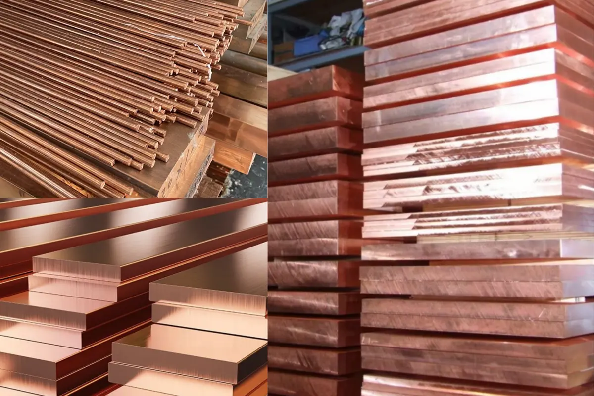
Copper is a naturally occurring non-ferrous metal with the chemical symbol Cu and atomic number 29. Commercially pure copper generally contains more than 99% copper, while its composition may be controlled or modified to meet different electrical, thermal, mechanical, and manufacturing requirements.
Physical and Functional Properties
Copper offers exceptional electrical and thermal conductivity, making it suitable for busbars, connectors, electrical contacts, heat sinks, and cooling components. It also provides good corrosion resistance in many atmospheric and water-based environments. The melting point of copper is approximately 1,085°C (1,984°F), although this property is more relevant to casting and high-temperature service than to CNC machining.
Ductility and Manufacturing Behavior
Copper’s high ductility allows it to be bent, drawn, and formed into thin or complex shapes without cracking. During cutting, however, the material may stretch or smear instead of breaking into short chips. High-purity grades prioritize conductivity and purity, while alloyed grades may provide greater strength or improved machinability, making grade selection important for precision parts.
What Is Copper CNC Machining?
Copper CNC machining is a subtractive manufacturing process in which computer-controlled cutting tools remove material from copper bars, plates, or prepared blanks. It provides the accuracy and repeatability required to manufacture custom copper parts with complex geometries, controlled dimensions, and functional surfaces.
How CNC Machining Shapes Copper Parts
A digital CAD model is converted into programmed toolpaths that control tool movement, cutting depth, spindle speed, and feed rate. Depending on the part geometry, copper machining may involve CNC milling, turning, drilling, tapping, or multi-axis operations to produce holes, threads, slots, cavities, thin walls, and complex contours.
Why CNC Machining Is Used for Copper
CNC machining is suitable for copper parts that require precise hole locations, consistent surface quality, or multiple features in a single setup. It supports prototypes and low-volume production while reducing variation between parts. However, producing reliable CNC machined copper parts still requires appropriate tooling, workholding, chip control, cooling, and machining parameters.
Which Copper Grades Are Best for CNC Machining?
The best copper grade depends on the required conductivity, purity, machinability, and cost. High-purity copper is preferred for demanding electrical, thermal, and vacuum applications, while free-machining copper alloys are more suitable when chip control, tool life, and production efficiency are priorities.
C101 and C102 Oxygen-Free Copper
C101 and C102 are oxygen-free copper grades with excellent electrical and thermal conductivity. C101 offers particularly high purity and is commonly used for semiconductor, high-vacuum, RF, and low-temperature components, while C102 is widely used for electrical and thermal parts. Both grades are highly ductile and can produce long chips, built-up edges, and burrs during machining.
C110 Electrolytic Tough Pitch Copper
C110, also known as C11000 or electrolytic tough pitch copper, is one of the most widely available commercial copper grades. It combines high conductivity with reasonable cost and material availability, making it suitable for busbars, terminals, electrical contacts, connectors, and heat sinks. Its machining behavior is similar to other pure copper grades, so sharp tools and effective chip control remain important.
C145 Tellurium Copper
C145 tellurium copper contains a small amount of tellurium that improves chip breaking and reduces adhesion to the cutting edge. It is easier to turn, drill, and tap than C101 or C110 while retaining high electrical and thermal conductivity. This balance makes C145 a practical choice for connectors, electrodes, threaded components, and production parts with complex machined features.
| Copper grade | Main advantage | Machinability | Typical applications |
| C101 | High purity and vacuum compatibility | Difficult | Semiconductor, vacuum and RF parts |
| C102 | High conductivity and low oxygen content | Difficult | Electrical and thermal components |
| C110 | Conductivity, availability and cost balance | Difficult to moderate | Busbars, contacts and heat sinks |
| C145 | Improved chip breaking | Good | Connectors, electrodes and turned parts |
How Does Copper CNC Machining Work?
Copper CNC machining begins with a CAD model and an appropriate copper grade selected according to the part’s functional requirements. CAM software converts the design into toolpaths that define the cutting sequence, spindle speed, feed rate, and depth of cut. The process then progresses from workpiece setup and rough machining to finishing, deburring, cleaning, and final inspection.
Workholding and Rough Machining
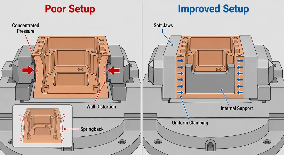
Copper stock must be held securely without being scratched, compressed, or distorted. Soft jaws, large-contact-area fixtures, and custom supports are often used to distribute clamping pressure, especially for thin-wall parts. Rough machining removes most of the excess material while leaving a controlled and uniform allowance for finishing. Stable tool engagement and effective chip evacuation help limit heat, tool adhesion, and chip recutting during this stage.
Finishing, Deburring, and Inspection
Finishing operations use sharp tools and controlled cutting parameters to achieve the required dimensions and surface finish. Holes, threads, sealing surfaces, and other critical features may be completed in the same setup to reduce positioning error. After machining, burrs are removed from edges and openings, and the part is cleaned to eliminate chips, coolant, and surface contamination. Final dimensions can then be verified using CMMs, micrometers, pin gauges, thread gauges, and other inspection equipment.
What CNC Processes Are Used for Copper Parts?
The appropriate CNC process depends on the shape, size, tolerance, and production volume of the part. Copper components may require milling, turning, drilling, tapping, or a combination of operations. Selecting the correct process helps reduce setups, control burrs, and maintain dimensional consistency.
The following table summarizes the most common processes used for CNC-machined copper parts and their key production considerations.
| CNC process | Best suited for | Key machining concern |
| CNC milling | Heat sinks, cooling plates, waveguides and electrodes | Burrs, chip evacuation and thin-wall distortion |
| CNC turning | Terminals, sleeves, connectors and round electrodes | Long chips and tool adhesion |
| Drilling and tapping | Holes, threads and internal features | Chip packing, hole-edge burrs and lubrication |
| 5-axis machining | Multi-sided parts and complex contours | Workholding, tool access and setup control |
| Mill-turn machining | Parts combining round and milled features | Process synchronization and chip control |
| EDM electrode machining | Detailed copper electrodes and complex profiles | Dimensional accuracy and surface consistency |
CNC Milling Copper
CNC milling uses rotating cutting tools to create flat surfaces, pockets, slots, holes, cooling channels, and complex contours. It is commonly used for copper heat sinks, cooling plates, waveguides, electrodes, and equipment bases. For parts with features on several faces, 5-axis copper machining can reduce repositioning and improve the accuracy between related surfaces.
CNC Turning Copper
CNC turning rotates the copper workpiece against a stationary cutting tool to produce cylindrical features such as shafts, sleeves, terminals, threaded connectors, and round electrodes. Because pure copper tends to produce continuous chips, suitable insert geometry and chip evacuation are important. Mill-turn machining can combine turned features with flats, cross-holes, slots, and other milled details in one setup.
Drilling and Tapping Copper
Drilling copper requires careful chip control because long chips can remain inside the hole, wrap around the drill, or damage the finished surface. Peck-drilling cycles and effective coolant delivery help clear chips from deep holes. During tapping, suitable lubrication and correct thread engagement reduce friction, material adhesion, and thread damage. C145 is generally easier to drill and tap than high-purity copper.
EDM Copper Electrode Machining
Copper is frequently CNC machined into EDM electrodes because of its high electrical and thermal conductivity, dimensional stability, and ability to reproduce fine details.
The electrode may include fine details, narrow ribs, deep cavities, or complex three-dimensional contours that reproduce the required shape in the final workpiece. Accurate machining and a consistent surface finish are essential because electrode geometry directly affects the EDM result.
What Makes Copper Difficult to Machine?
Copper machining challenges come mainly from the material’s softness and ductility. Instead of breaking cleanly, copper may deform, adhere to tools, and produce continuous chips, affecting accuracy and surface quality.
Tool Adhesion and Built-Up Edge
Copper can adhere to the cutting edge and form a built-up edge, changing the tool geometry and causing rough surfaces, dimensional variation, and faster tool wear.
Long and Stringy Chips
Pure copper often produces continuous chips that can wrap around the tool or workpiece. This is especially problematic during turning, deep-hole drilling, and narrow-slot machining.
Burrs and Surface Smearing
Copper may stretch across edges, leaving burrs around holes, slots, and threads. Dull tools can also smear the surface, affecting assembly, sealing, and electrical contact.
Distortion and Dimensional Instability
Thin copper features may deform under clamping pressure, cutting forces, or temperature changes. Dimensions can shift after the fixture is released or the part returns to room temperature.
Best Tools and Cutting Strategies for Copper
Reliable copper machining requires sharp tools, stable cutting parameters, effective cooling, and secure workholding. These factors work together to control adhesion, chip formation, burrs, and dimensional variation.
Cutting Tool Material and Geometry
Sharp carbide tools with positive rake angles help cut copper cleanly with lower forces. Polished cutting edges and flutes reduce friction and material adhesion, while low-friction coatings may benefit demanding applications.
Speeds, Feeds, and Chip Load
Speeds and feeds should match the copper grade, tool size, machine rigidity, and part geometry. Very light feeds can cause rubbing, while aggressive parameters may deform thin features. A stable chip load supports cleaner cutting.
Coolant, Lubrication, and Chip Removal
Coolant lubricates the cutting zone, controls temperature, and removes chips. Directed flow is especially useful for drilling, tapping, deep pockets, and narrow slots where chips can accumulate or scratch finished surfaces.
Workholding and Machining Sequence
Soft jaws, vacuum fixtures, and custom supports help prevent surface damage and clamping distortion. Thin-wall parts may require staged or symmetrical machining, uniform finishing allowance, and fewer setups to maintain accuracy.
How to Improve Copper Surface Finish and Accuracy
Copper surface finish and accuracy depend on sharp tools, stable cutting conditions, effective chip removal, controlled temperature, and suitable inspection methods.
Controlling Surface Finish and Burrs
Sharp tools, consistent feeds, and smooth toolpaths reduce tearing and surface smearing. Efficient chip evacuation prevents scratches, while chamfers and suitable deburring methods improve edges around holes, slots, and threads.
Managing Tolerances and Thermal Effects
Rigid setups, low-runout tools, balanced cutting, and controlled clamping improve dimensional stability. Before final machining or inspection, the workpiece should reach a stable temperature, especially for thin-wall and tight-tolerance parts.
Inspection and Documentation
CMMs, micrometers, pin gauges, and thread gauges can verify critical features. Material certificates, COCs, and dimensional inspection reports may also be provided when traceability is required.
Surface Finishing Options for Machined Copper Parts
Copper parts may remain as-machined or receive additional finishing to improve appearance, oxidation resistance, solderability, wear resistance, or electrical contact. The selected process must account for cleanliness, conductivity, and dimensional requirements.
Polishing and Electropolishing
Mechanical polishing reduces machining marks and creates a brighter surface, while electropolishing removes a thin surface layer electrochemically. Material removal must be controlled on tight-tolerance features and critical contact surfaces.
Plating and Protective Coatings
Nickel, tin, or silver plating can improve oxidation resistance, solderability, wear resistance, or contact performance. Coating thickness must be considered for holes, threads, and mating features.
Bead Blasting and Mechanical Finishing
Bead blasting creates a uniform matte texture, while brushing produces a directional finish. These treatments should be avoided on sealing surfaces, precision fits, and electrical contacts unless specified.
Applications of CNC-Machined Copper Parts
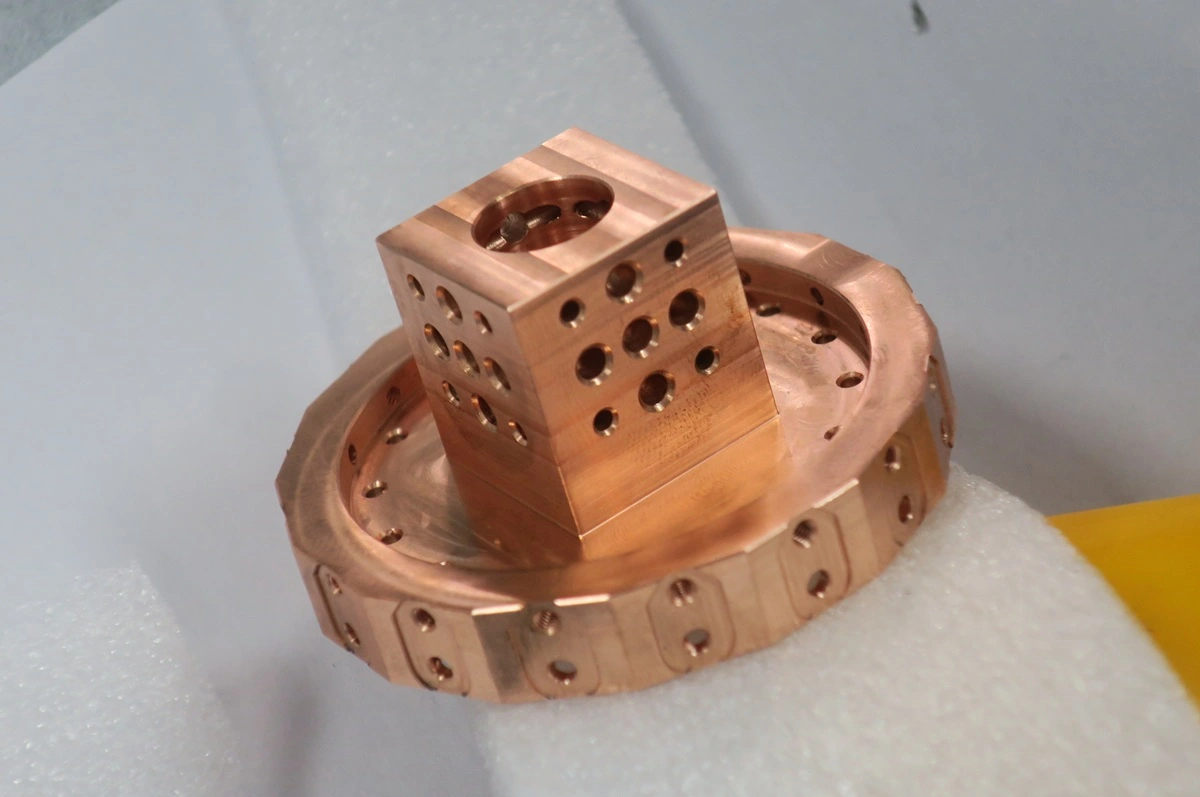
Copper’s conductivity, heat-transfer performance, corrosion resistance, and vacuum compatibility make it suitable for components that manage electricity, heat, and electromagnetic energy.
Electronics and Power Distribution
C110 and C145 are commonly machined into busbars, terminals, contacts, and connectors. These parts require accurate features, clean mating surfaces, and effective burr control.
Heat Sinks and Thermal Management
Copper heat sinks, cooling plates, and thermal spreaders transfer heat away from electronic devices. CNC milling can produce mounting holes, channels, fins, and sealing surfaces in one component.
Semiconductor and Vacuum Equipment
C101 and C102 oxygen-free copper are used for vacuum parts, conductive fixtures, cooling components, and high-purity hardware requiring controlled chemistry, cleanliness, and dimensional accuracy.
Photonics, RF, and Electrode Components
Precision copper machining produces RF housings, waveguides, optical components, and EDM electrodes. These parts often require accurate cavities, profiles, interfaces, and mounting features.
Design Guidelines for Machined Copper Parts
Copper parts should be designed to limit distortion, burrs, and unnecessary machining. Geometry, tolerances, and finishing requirements must suit the selected copper grade and part function.
Walls, Holes, and Internal Corners
Avoid unsupported thin walls, deep narrow slots, and unnecessarily small holes. Use standard internal corner radii and add chamfers where deburring or assembly is important. Minimum wall thickness should be evaluated according to the part size and geometry.
Tolerances, Surface Finish, and Contact Areas
Apply tight tolerances only to functional features. Clearly identify critical contact, sealing, and cosmetic surfaces on the drawing. If plating is required, account for coating thickness on holes, threads, and mating features.
Copper CNC Machining Services at Rollyu
Rollyu manufactures custom copper parts for electrical, thermal, semiconductor, and precision equipment applications. Our capabilities cover copper milling, turning, drilling, tapping, and multi-axis machining.
Prototype and Low-Volume Production
We machine C101, C102, C110, C145, and other copper grades for prototypes and low-volume production. Each project is reviewed according to its material, geometry, tolerance, surface finish, and application requirements.
Quality Control and Traceability
Rollyu operates under ISO 9001:2015 and ISO 13485:2016 quality systems. Copper parts can be verified using CMMs, gauges, and other inspection equipment, with material certificates, COCs, and dimensional inspection reports available when required.
F A Q
Can Pure Copper Be CNC Machined?
Yes. Pure copper can be milled, turned, drilled, and tapped using sharp tools, suitable parameters, effective cooling, and controlled workholding.
Why Is Pure Copper Difficult to CNC Machine?
Its softness and ductility promote tool adhesion, long chips, burrs, surface smearing, and dimensional distortion.
Which Copper Grade Is Best for CNC Machining?
Among the grades covered here, C145 offers the best machinability. C101 suits high-purity applications, while C110 balances conductivity, availability, and cost.
What Is the Difference Between C101 and C110 Copper?
C101 is high-purity oxygen-free copper. C110 is electrolytic tough pitch copper commonly used for general electrical and thermal parts.
What Tools Are Best for Machining Copper?
Sharp carbide tools with positive rake angles and polished cutting edges help reduce cutting forces, adhesion, and surface damage.
Do Machined Copper Parts Require Surface Finishing?
Not always. Polishing, plating, or bead blasting is applied only when additional appearance, protection, solderability, or contact performance is required.
Why Is Copper CNC Machining More Expensive Than Aluminum?
Copper has a higher material cost and often requires more careful chip control, deburring, workholding, and inspection than aluminum.
Conclusion
Successful copper CNC machining depends on selecting the correct grade and controlling tooling, chip formation, cooling, workholding, and inspection. Rollyu provides precision milling, turning, and multi-axis machining for custom copper parts, supporting prototypes and low-volume production for electrical, thermal management, semiconductor, and precision equipment applications.
