
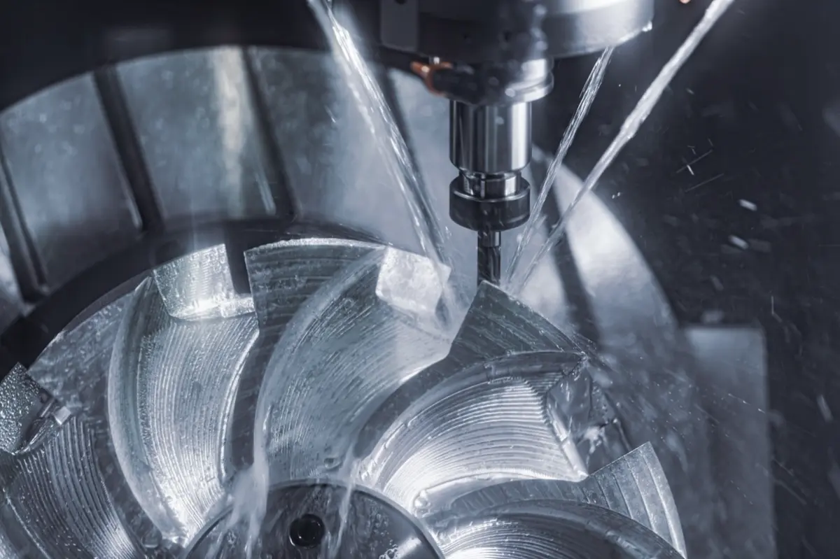

Choose CNC cutting tools around the feature, material, and tolerance before locking the part design.
A CAD model can show sharp corners, deep pockets, and small threads, but the machine still needs a cutter that can reach the feature, stay stiff, clear chips, and hold size. When the design forces that tool path, the cost shows up as chatter, burrs, taper, broken taps, or dimensions that drift during production.
This guide explains common CNC cutting tools, the features each tool makes, and the design limits that affect part quality. Use these checks before sending RFQs for tight pockets, small holes, fine threads, cosmetic faces, or tight-tolerance machined parts.
What Are CNC Cutting Tools in CNC Machining?
CNC cutting tools are the physical tools that remove material in milling, turning, drilling, boring, reaming, tapping, and thread milling. The CNC program controls motion, speed, feed, and depth of cut, but the tool’s diameter, flute shape, length, coating, and edge condition decide what the part can physically become.
That tool choice affects more than cycle time. A cutter that is too long can deflect. A dull tool can push material instead of cutting cleanly. A tool that cannot evacuate chips can recut metal and scratch the wall. Tooling decisions become part quality decisions once tolerance, finish, and assembly fit matter.
Types of CNC Cutting Tools and Their Machined Features
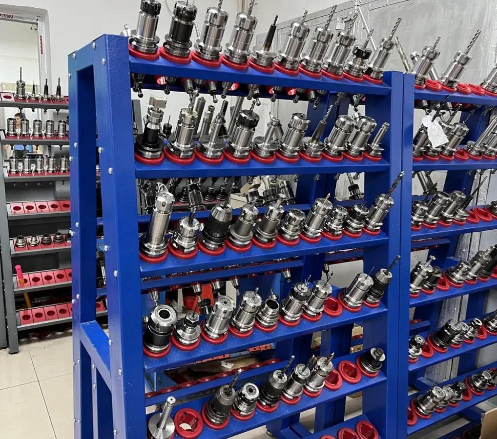
Each CNC cutting tool fits a feature family. Matching the cutter to the feature prevents design assumptions from becoming shop-floor rework.
| CNC cutting tool | Common machined features | Main quality risk |
|---|---|---|
| End mill | Slots, pockets, contours, shoulders, bosses | Deflection, chatter, corner radius limits |
| Drill, boring tool, reamer | Holes, bores, dowel holes, bearing seats | Positional error, oversize or undersize holes |
| Tap, thread mill | Internal and external threads | Broken taps, poor thread fit, weak minor diameter |
| Turning insert | Shafts, pins, sleeves, grooves, tapers | Insert wear, poor concentricity, tool marks |
End Mills for Slots, Pockets, and Contours
End mills cut slots, pockets, shoulders, profiles, bosses, and 3D contours. Flat end mills leave flat floors, ball end mills finish curved surfaces, and corner-radius end mills reduce edge stress while improving tool life in heavier cuts.
Small end mills reach tighter details but carry less stiffness. If a slot, pocket, or internal corner needs a small-diameter cutter, the quote should account for slower cutting, higher breakage risk, and closer inspection.
Drills, Boring Tools, and Reamers for Holes
Drills create the starting hole. Boring tools correct location or diameter after drilling. Reamers finish holes that need closer size control or smoother walls.
A drilled hole alone may be enough for clearance screws or fluid passages. Bearing seats, dowel holes, and press-fit bores often need boring or reaming because the boring vs drilling decision affects roundness, location, and surface finish.
Taps and Thread Mills for Threaded Features
Taps cut internal threads at a fixed diameter and pitch. Tapping is fast, but a broken tap can scrap a high-value part when the shop cannot remove the broken tool without damaging the hole.
Thread mills cut threads by moving a smaller cutter in a helical path. Thread milling is slower, but thread mills can reduce broken-tool risk in blind holes, large threads, hard metals, and expensive parts where thread quality affects assembly.
Turning Inserts for Round Parts
Turning inserts cut round parts while the workpiece rotates. Inserts shape outside diameters, inside diameters, grooves, faces, tapers, radii, and threads on shafts, pins, bushings, spacers, connectors, and sleeves. Insert grade, nose radius, chip breaker, and toolholder rigidity affect finish and size control. A large nose radius can improve finish but raise cutting pressure on slender parts, while a sharper insert can reduce pressure but wear faster in abrasive materials.
How Cutting Tool Geometry Limits CNC Part Design
Cutting tool geometry creates hard design limits. Round cutters, tool length, cutter diameter, flute length, and material behavior decide whether a model is simple to machine or risky to quote.
Internal Corner Radius
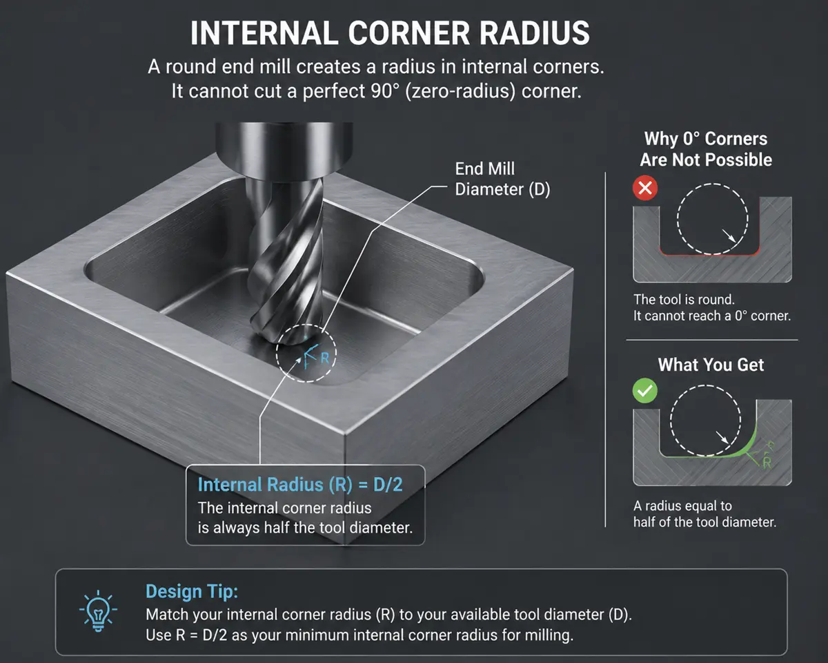
End mills are round, so milled internal corners need a radius. A zero-radius inside corner usually needs a relief feature, sinker EDM, broaching, or a design change. Match the internal radius to a practical cutter size, then add clearance if a mating part needs to seat fully. Small internal radii force smaller tools, slower cuts, more passes, and higher tool breakage risk.
Deep Pockets and Long-Reach Tools
Long-reach tools behave like springs. As pocket depth rises, the cutter can bend away from the programmed path, leaving tapered walls, chatter marks, poor floor finish, or corners that miss size.
Review deep pockets before quoting, especially when pocket depth is more than about three times pocket width. Wider radii, relief cuts, multi-side access, or a split-part design can reduce tool deflection and chip packing.
Small Holes and Fine Threads
Small holes need small drills, and small drills break more easily under heat, runout, or poor chip evacuation. Deep small holes add another problem because chips have farther to travel before leaving the cut.
Fine threads create similar risk. The minor diameter leaves less thread root strength, and a tap can wedge in gummy metals or deep blind holes. For costly parts, engineers should review the thread milling vs tapping choice before the drawing locks the hole callout.
Material-Specific Tooling Limits
Material behavior changes the cutting tool choice because each material fails in a different way at the cutting edge.
- Aluminum: Sharp polished tools help reduce built-up edge when soft chips weld to the cutter.
- Stainless steel: Positive cutting action matters because rubbing can work harden the surface.
- Titanium: Heat stays near the cutting edge, so tool coating, coolant, and conservative tool life matter.
- PEEK, POM, PTFE, and other plastics: Sharp tools, light clamping, and heat control help reduce movement during machining.
In semiconductor CNC machining, tool heat and edge wear can affect vacuum fixtures, wafer-handling parts, and alignment features where surface condition and dimensional stability carry higher risk. The supplier should review material choice, cutter path, coolant strategy, and inspection method together before production.
How Tool Choice and Tool Wear Create Part Quality Risks
Tool selection and tool wear can move a part out of spec even when the toolpath is correct. The main risks are size drift, surface damage, burrs, chatter, and late inspection failure.
Tolerance Drift and Feature Size Errors
Cutting edges wear with heat, pressure, and abrasive material contact. Tool wear changes the effective cutting diameter and cutting pressure, so slots, bores, profiles, and thread features can move away from nominal.
Rollyu Precision states CNC machining capability down to ±0.005 mm for tight-tolerance work, so parts near that range need tool-life controls, stable workholding, and measured inspection data. A tolerance number alone does not show whether a supplier can control the feature through machining and inspection.
Surface Finish, Burrs, and Chatter
Poor tool choice leaves visible and measurable damage. A dull cutting edge rubs and smears material. A tool with poor chip evacuation recuts chips against the wall. An unstable setup can leave chatter marks that affect sealing faces, bearing seats, sliding surfaces, and cosmetic areas.
Burrs create assembly risk when the part must seat against another component. A burr around a hole can block a fastener head, throw off a press fit, or damage a gasket surface. Deburring helps, but heavy burrs often point back to tool geometry, wear, feed rate, or material behavior.
DFM and Inspection Checks Before Quoting
Design for manufacturability review should happen before quoting when the drawing includes narrow slots, deep pockets, small holes, fine threads, tight fits, or cosmetic surfaces. For CNC machining parts, a quote-ready review should check whether the tool can reach the feature, hold stiffness, clear chips, and leave enough inspection access.
Check these items before sending the RFQ:
- Minimum internal radius: Can a standard cutter reach the corner without forcing a fragile tool?
- Pocket depth and access: Can chips leave the pocket without recutting the wall?
- Hole size and depth: Does the hole need drilling only, or drilling plus boring, reaming, or thread milling?
- Material behavior: Does the material create heat, work hardening, built-up edge, or plastic movement?
- Inspection method: Can CMM inspection, bore gauges, thread gauges, surface roughness checks, visual inspection, or first article inspection verify the risky feature before the batch repeats an error?
- Finish and deburring: Will coating, anodizing, polishing, or deburring change the final fit?
FAQ
How Do Speeds and Feeds Affect CNC Cutting Tool Performance?
Speeds and feeds control heat, chip thickness, and tool load. Excess speed can burn the edge, while weak feed can make the tool rub instead of cut. Heavy feed can break a small tool or push a slender part out of position.
When Should CNC Shops Use Carbide Cutting Tools Instead of HSS Tools?
Use carbide when stiffness, heat resistance, and wear life matter. Carbide works well for harder metals, production runs, tight features, and high-speed machining. HSS can still fit lower-volume work, less rigid setups, and operations where tool cost matters more than cutting speed.
When Does Tool Coating Matter in CNC Machining?
Tool coating matters when heat, friction, or chip welding is high. Coatings can reduce edge wear, built-up edge, or friction in the right material. Coating cannot fix poor tool access, bad chip evacuation, or an unstable setup.
Does Coolant or Cutting Fluid Affect Tool Life and Part Accuracy?
Yes, coolant affects heat, chips, tool life, and size control. Cutting fluid can carry heat away, lubricate the cut, and help move chips out of the feature. In plastics, poor heat control can shift dimensions or damage the machined finish.
What Happens if Chips Are Not Cleared During CNC Machining?
Poor chip clearing can scratch surfaces and break tools. Packed chips can recut the wall, trap heat, overload the cutter, and mark the finish. Blind holes, deep pockets, and gummy materials need chip evacuation review before machining starts.
