
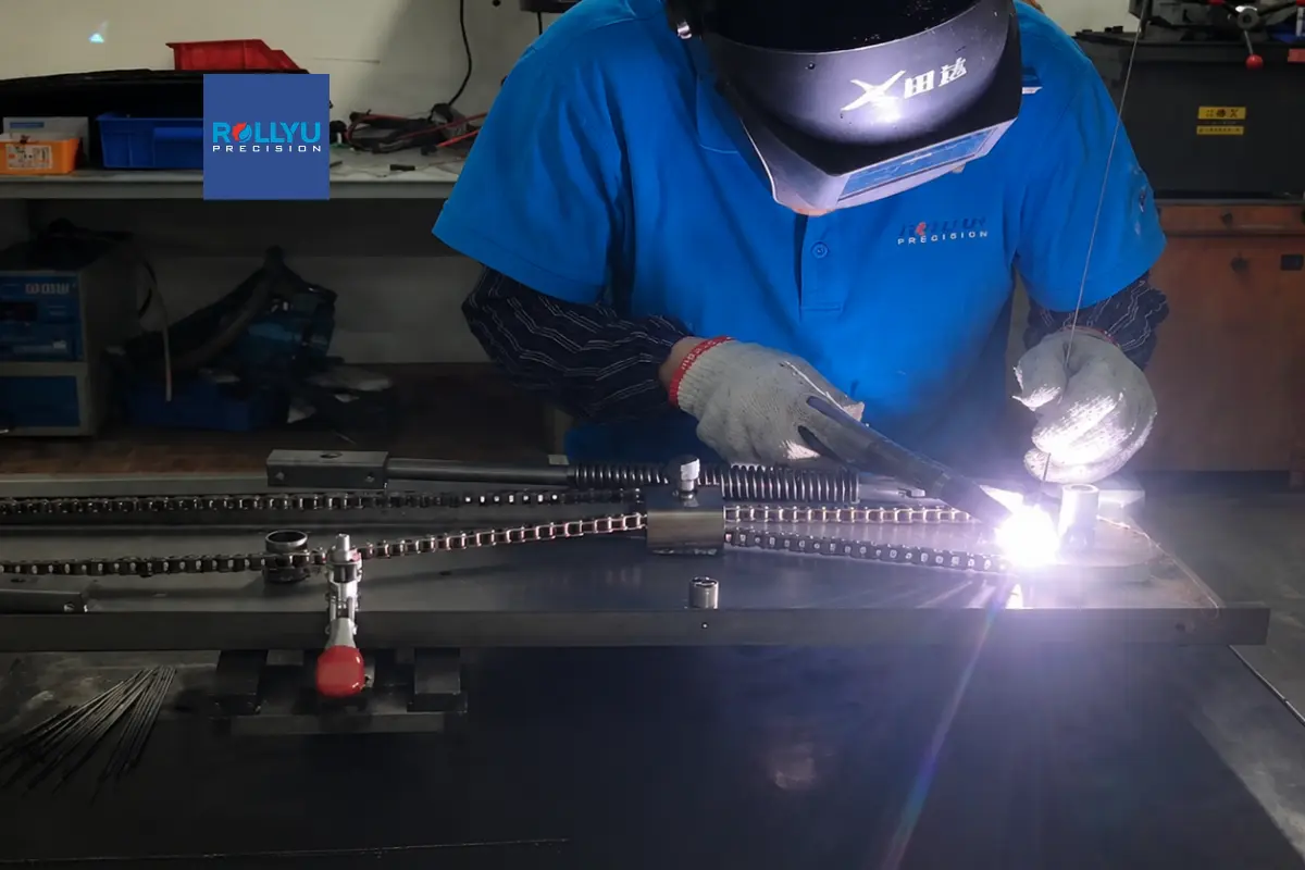

Qualified procedures, clean fit-up, and stable parameters reduce welding defect risk in sheet metal, while drawing-based inspection determines whether a weld is acceptable. For nonstructural sheet metal, AWS D9.1/D9.1M:2018 sets qualification, workmanship, and inspection requirements for arc and braze welding at thicknesses up to 0.2391 in. (6.07 mm).
Thin sheet reacts quickly to excess heat, poor contact, and contamination, so a small process shift can cause burn-through, weak spot-weld nuggets, or distortion before the bead looks wrong. Inspection should check both the weld and the finished assembly.
What Are Welding Defects in Sheet Metal Parts?
A welding defect is a discontinuity that exceeds the part’s acceptance criteria. The AWS Visual Inspection Workshop uses the same distinction: a defect is a discontinuity that fails the product specification. The drawing, governing code, service load, sealing requirement, and cosmetic class decide whether porosity, undercut, distortion, or an uneven bead is rejectable. This distinction prevents unnecessary repair, which can add heat, thin the parent metal, and create new distortion.
What Are the Most Common Welding Defects and Their Causes?
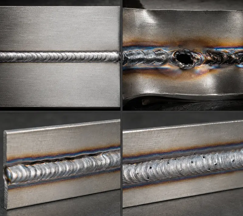
Most welding defects trace to contamination, unstable heat input, poor joint access, loose fit-up, or an unqualified weld schedule, and thin sheet leaves little margin before these shifts change weld quality or part geometry.
| Defect | Typical causes | Main risk |
|---|---|---|
| Porosity | Oil, moisture, oxide, paint, drafts, or weak shielding | Leaks, reduced section, or poor finish |
| Inclusions | Slag, oxide films, or tungsten contamination | Local loss of weld strength |
| Cracks | High restraint, poor crater fill, rapid cooling, or unsuitable filler | Crack growth under load or vibration |
| Lack of fusion or penetration | Low heat, fast travel, poor access, tight root gap, or misalignment | Joint strength below the drawing requirement |
| Undercut, overlap, or underfill | Wrong heat input, poor torch angle, unstable travel, or incorrect filler rate | A reduced section or unfused weld edge |
| Distortion or burn-through | Concentrated heat, wide gaps, slow travel, or weak restraint | Failed flatness, hole position, fit, or sealing |
| Spot weld expulsion | Excess current or time, low electrode force, dirty interfaces, or worn caps | Lost nugget volume, surface marks, or electrode wear |
| Undersized spot weld nugget | Low current, short time, excessive force, shunting, or poor sheet contact | Low spot weld strength |
Porosity, Inclusions, and Cracks
Porosity forms when gas becomes trapped as the weld pool solidifies. Inclusions form when slag, oxide, or tungsten remains inside the weld metal. Cracks can start in the weld metal, crater, heat-affected zone, or parent metal and usually require engineering review under the applicable acceptance criteria.
Fusion, Penetration, and Bead Profile Defects
Lack of fusion leaves an unfused boundary between the weld metal and joint face. Incomplete penetration leaves the root shallower than the drawing requires, while undercut, overlap, or underfill changes the specified bead profile. A smooth surface can hide fusion or penetration loss.
Heat-Related Distortion and Burn-Through
Distortion develops when the heated weld zone expands and shrinks unevenly. A weld can meet local bead criteria while the assembly fails flatness, flange angle, or hole position.
Burn-through occurs when excess heat or a wide gap lets the weld pool collapse through the sheet. Thin aluminum and stainless steel leave little margin between incomplete fusion and a hole.
Spot Weld Expulsion and Undersized Nuggets
Expulsion ejects molten metal from between the sheets and may reduce the finished nugget. An undersized nugget forms when low effective heat or poor sheet contact limits nugget growth, while a deep electrode mark does not prove adequate nugget size.
How Can Welding Defects Be Prevented?
Prevent welding defects by controlling the process before the arc or electrodes touch the part. Match the process, joint, fixture, and weld schedule to the material, thickness, finish, and acceptance criteria.
Welding Process and Joint Design
Choose the process from sheet thickness, joint access, production volume, and appearance. TIG welding gives the operator close control on thin sections and visible seams, while MIG welding deposits metal faster on longer production welds when the transfer mode suits the sheet. Resistance spot welding joins overlapping sheets without a continuous bead.
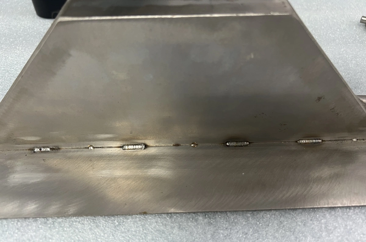
Choosing between MIG and TIG welding changes filler control, access, speed, and cosmetic cleanup. Joint design then controls how heat reaches the root. Specify lap width, root opening, weld length, pitch, and torch or electrode access. Use intermittent welds when they carry the load and the drawing does not require a sealed seam.
Surface Preparation and Fit-Up Control
Prepare the surfaces and establish fit-up before welding starts.
- Remove oil, moisture, oxide, scale, paint, and incompatible coatings with a method approved for the alloy. Keep aluminum and stainless steel tools separate from carbon steel tools.
- Hold the joint gap, overlap, edge alignment, and contact pressure within the qualified range. Fixtures should locate the part without forcing mismatched edges together.
- Set tack welds and fixtures so the assembly stays aligned through final welding. Before final welding, review cut edges, bends, fixture datums, tack placement, welding, and finishing as one sheet metal fabrication workflow.
Arc and Spot Welding Parameter Control
A qualified parameter window keeps heat input and force inside a repeatable range. Record the variables that change weld size, penetration, expulsion, or distortion.
- Arc welding: Control current, voltage, travel speed, wire feed, electrode extension, torch angle, shielding gas, pulse settings, and filler metal.
- Spot welding: Control current, weld time, squeeze time, hold time, electrode force, cap shape, cooling, and weld spacing.
- Process checks: Verify equipment calibration, gas delivery, grounding, electrode alignment, consumable condition, and fixture contact before production.
Do not copy fixed settings between different materials or gauges. A schedule proven on 1 mm cold-rolled steel may fail on coated steel, stainless steel, or aluminum of the same nominal thickness.
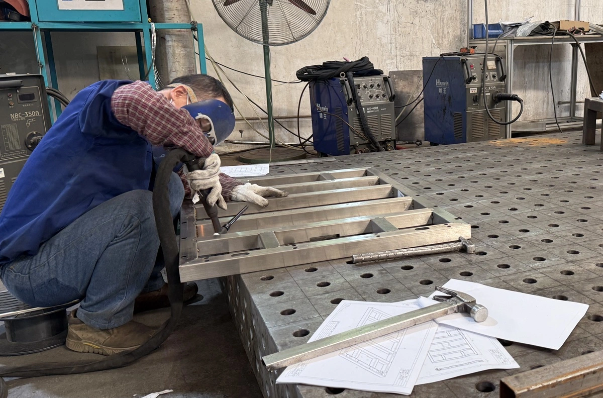
Heat Control, Weld Sequence, and Procedure Compliance
Reduce distortion by limiting concentrated heat and balancing shrinkage across the assembly. Short weld segments, pulse control, copper backing, chill bars, and cooling pauses can help. The fixture should restrain movement without locking excessive stress into the sheet.
Plan the weld sequence to distribute heat across the assembly. Tack placement, skip welding, and balanced welds are standard controls for preventing warpage in welded sheet metal. Follow the approved procedure, drawing, and work instructions, and review the procedure when the alloy, thickness, filler, joint, coating, machine, or essential parameter range changes.
How Are Welding Defects Detected and Evaluated?
Weld inspection should target discontinuities that threaten fit, load path, sealing, or appearance. Before production, define the method, timing, sample size, acceptance criteria, repair route, and required records.
Inspection Before, During, and After Welding
Visual inspection starts before welding and continues through final assembly. ISO 17637:2016 covers visual testing of fusion welds and also allows testing before welding.
| Stage | What to check | What the check can reveal |
|---|---|---|
| Before welding | Material, thickness, cleanliness, root opening, overlap, tacks, fixture contact, and procedure revision | Contamination, poor fit-up, wrong material, or joint mismatch |
| During welding | Arc stability, shielding, electrode condition, interpass cleaning, bead placement, expulsion, and part movement | Porosity, inclusions, unstable weld size, or distortion |
| After cooling | Weld location, size, profile, undercut, overlap, pores, cracks, crater fill, spatter, flatness, flange angle, hole position, and fit | Surface defects or out-of-tolerance assembly geometry |
Surface and Internal Nondestructive Testing
Nondestructive testing must match the material, thickness, joint geometry, and defect orientation. ISO 17635:2025 bases method selection on the quality requirements, material, weld thickness, welding process, and test extent.
| Method | Best suited to finding | Main limitation |
|---|---|---|
| Liquid penetrant | Surface-breaking discontinuities on clean, nonporous metals | Does not find subsurface discontinuities |
| Magnetic particle | Surface and near-surface indications in ferromagnetic metals | Not suitable for aluminum or most austenitic stainless steel |
| Radiographic | Internal volumetric conditions such as porosity | Access, joint angle, cost, and radiation controls |
| Ultrasonic | Internal reflectors when a proven thin-sheet technique is available | Thin sections and joint geometry can limit interpretation |
| Leak or pressure testing | Leakage through sealed enclosures or fluid paths | Finds a leak path but may not identify the defect type |
Sealed parts or traceable production may require more than one inspection method and documented results.
Spot Weld Testing
Spot weld testing checks nugget size, failure mode, surface condition, and process consistency. Visual checks can flag expulsion, deep electrode marks, cracks, misalignment, or missing welds, but the visible indentation does not prove nugget size.
ISO 10447:2022 covers peel and chisel testing for resistance spot and projection welds in two or more sheets from 0.5 mm to 3.0 mm. Destructive peel tests reveal weld size and failure mode. Nondestructive chisel tests verify selected welds, while macrosections or mechanical tests can support procedure qualification and periodic validation.
Acceptance, Repair, Reinspection, and Records
Treat acceptance, repair, and reinspection as one controlled cycle.
- Apply written criteria. ISO 5817:2023 defines quality levels B, C, and D for steel, nickel, and titanium fusion welds at material thicknesses of 0.5 mm or more, excluding beam welding. Level B carries the highest requirement. ISO 10042:2018 provides separate levels for aluminum arc welds. The drawing or application standard selects the required level.
- Complete the repair. Mark the rejected area and remove the defect without reducing the parent metal below its permitted thickness. Reweld under an approved repair procedure, then reinspect with the original method. Repeated repairs need engineering review because grinding and reheating can thin or distort sheet metal.
- Close the record. Record the procedure revision, welder or operator ID, material lot, weld settings, inspection results, nonconformance details, repairs, and reinspection status. Rollyu Precision holds ISO 9001:2015 and ISO 13485:2016 certifications and supports in-process inspection, final inspection, and traceability. These controls do not replace project-specific acceptance criteria.
FAQs
Does Every Welded Sheet Metal Part Need Nondestructive Testing?
No. The drawing, code, and service risk set the inspection scope, which may be visual inspection alone. Add penetrant, magnetic particle, radiographic, ultrasonic, or leak testing when failure consequences, joint geometry, production history, or customer requirements justify the added coverage.
Can Grinding a Weld Hide or Worsen a Defect?
Yes. Grinding can smear metal over a crack or pore, remove evidence of undercut, thin the parent sheet, and add heat. A repair plan should define the removal limit, permitted tools, final profile, and reinspection method. Cosmetic blending does not convert an unacceptable weld into an acceptable weld.
Can Powder Coating Seal a Porous or Leaking Weld?
No, not as a qualified weld repair. Powder coating is a finish, not a structural repair or qualified leak seal. Coating may bridge a small opening visually, while trapped contamination or leakage remains below the film. Inspect and leak-test the bare weld before coating, then repeat the leak test after finishing when the drawing requires it.
What Welding Details Should a Drawing or RFQ Include?
A welding drawing or RFQ should state material grade, thickness, joint type, weld symbol, size, length, pitch, location, finish, and quantity. Add flatness or distortion limits, cosmetic class, governing code, acceptance criteria, inspection method, leak rate, documentation, and repair restrictions. These inputs let the supplier quote the intended process and inspection scope.
When Should Riveting or Mechanical Fasteners Replace Welding?
Use riveting or mechanical fasteners when welding heat would damage thin sheet, coatings, electronics, or tight assembly geometry. Fasteners also suit field assembly, disassembly, dissimilar materials, and one-sided access when a blind fastener works. The riveting versus welding decision should compare load path, sealing, corrosion, appearance, access, and maintenance needs.
