
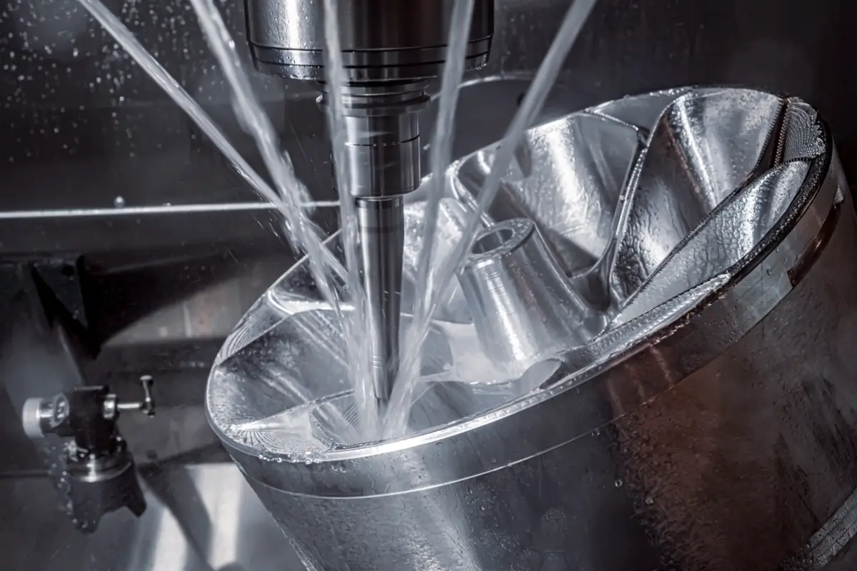

Use STEP for CNC machining, tight tolerance quotes, assemblies, and DFM review. Use STL for simple 3D printing when only the outer shape matters. ISO 10303-21:2016 defines STEP Part 21 as an exchange format for product data, while the Library of Congress describes STL as a triangular surface mesh first documented by 3D Systems in 1988.
The manufacturing risk is not the file extension alone. The risk is whether the supplier can read geometry, units, tolerances, and design intent before quoting or building the part.
What Is the Main Difference Between STEP and STL?
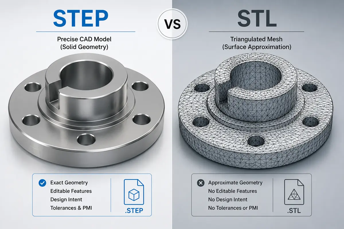
STEP stores editable CAD geometry and product data. STL stores a tessellated surface, which turns curves and features into triangles. This difference controls how much a supplier can check before quoting, machining, printing, or inspecting the part.
STEP Stores CAD Geometry and Manufacturing Data
A STEP file preserves the solid model, surfaces, assemblies, units, and feature relationships that a CAD or CAM system can read. STEP can also carry product and manufacturing information when the CAD export includes model based definition data, although a 2D drawing still helps control tolerances and inspection notes.
STEP works well when the supplier must machine pockets, bores, threads, mating faces, and datum controlled features. CNC programmers can use the STEP geometry to create toolpaths, check feature access, and review whether workholding will distort thin walls or critical faces.
STL Stores a Triangular Surface Mesh
An STL file stores the outside skin of a model as triangular facets. The Library of Congress notes that STL stores vertex coordinates and outward normal vectors for each triangular facet, while STL does not provide standard support for color, texture, or other common CAD model attributes.
STL works when a slicer only needs a closed mesh for 3D printing. STL becomes risky when the supplier needs exact hole locations, thread callouts, datum references, material notes, or tolerance targets for precision manufacturing.
Geometry, Editability, and Quote Risk
STEP and STL can describe the same visible shape, but only STEP keeps the CAD data needed for most manufacturing decisions. STL can look correct on screen while hiding missing units, coarse facets, open edges, or lost feature intent.
| Quote Factor | STEP | STL |
|---|---|---|
| Geometry type | Editable CAD solids and surfaces | Triangular surface mesh |
| Process fit | CNC machining, assemblies, DFM review, inspection planning | 3D printing, visual models, simple fit prototypes |
| Units | Stored in CAD exchange data when exported correctly | Not stored as a standard STL property |
| Tolerances | Can include PMI when exported correctly, but drawings are still common | Not stored in standard STL |
| Main quote risk | Missing drawing or unclear PMI | Mesh defects, scale errors, lost design intent |
When to Use STEP for CNC Machining
Use STEP for CNC machining when the part has machined features, controlled dimensions, mating surfaces, or inspection requirements. A STEP file gives the supplier geometry for programming, DFM review, and inspection against a drawing or model based definition package.
CNC Milling and Turning Parts
STEP is the safer quote file for CNC milling and turning. Toolpaths come from clean CAD geometry. Pockets, slots, bosses, turned diameters, counterbores, chamfers, and fillets all need exact surfaces rather than triangle approximations.
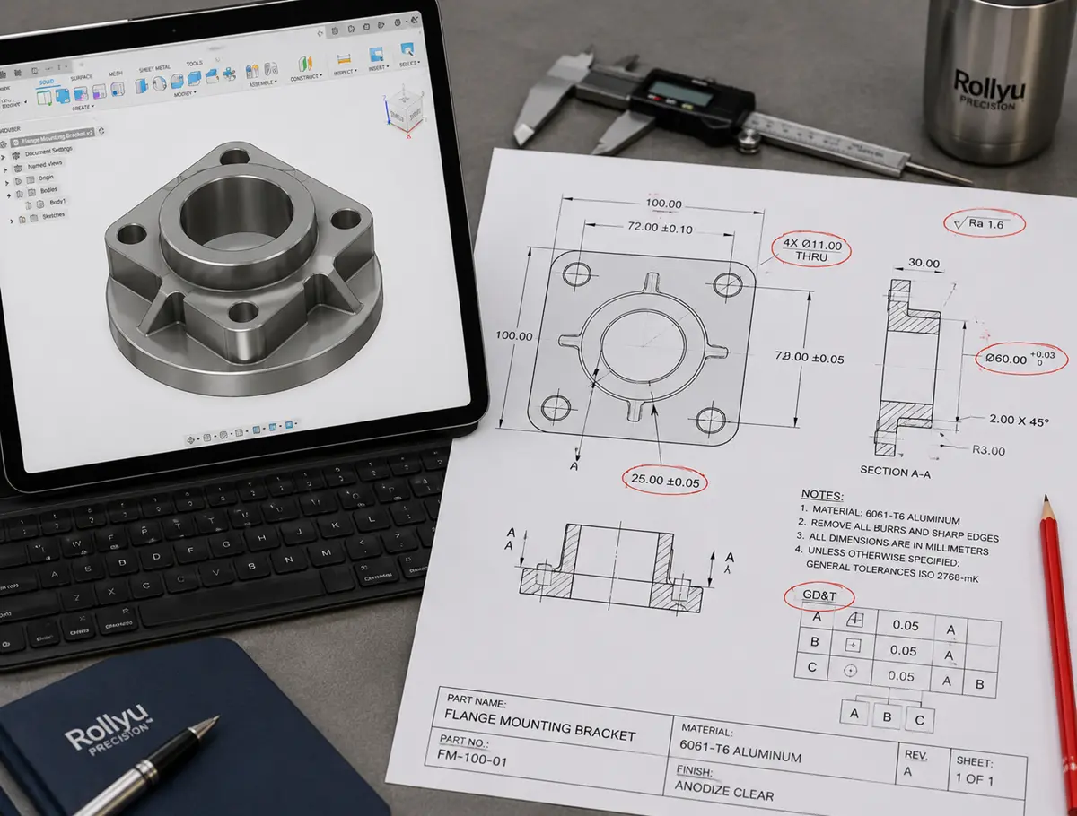
Send STEP together with a PDF drawing when the part includes material callouts, surface finish, thread specs, or feature tolerances. For functional prototypes, CNC prototype machining needs the same package so the supplier can price tool access, material behavior, and inspection before cutting metal or plastic.
Tight-Tolerance Features
STEP is the better file when a feature must hold a tight tolerance. The machinist needs exact geometry and a clear inspection target. STL triangle size can change round holes, sealing faces, datum pads, and small slots enough to create quote uncertainty.
Rollyu’s published CNC capability lists tolerance down to +/-0.005 mm, but the practical tolerance plan still depends on material, feature geometry, setup, tool access, and inspection method. Send a drawing for any critical dimension that affects fit, sealing, motion, optical alignment, or assembly stackup.
DFM Review and Inspection Planning
STEP gives DFM reviewers enough model detail to check thin walls, deep pockets, internal corner radii, standard hole sizes, workholding faces, and tool access. DFM review catches features that look harmless in CAD but add cost or rework risk on the machine.
For inspection heavy projects, connect the STEP model with a drawing that marks datums, tolerances, surface finish, thread class, and report requirements. Those same notes support first article inspection, where dimensional reports and supplier review help buyers confirm the baseline before production starts.
When STL Works for 3D Printing
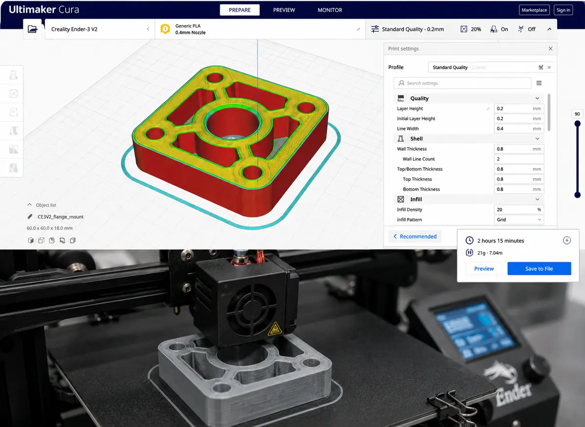
STL works for 3D printing when the job only needs a printable outer shape. STL fits concept models, simple fit checks, and single material prototypes, but the format becomes weak when the printed part needs exact engineering data or controlled manufacturing notes.
Visual Prototypes and Simple Fit Checks
STL fits visual prototypes, ergonomic models, enclosure mockups, and early fit checks. The slicer reads the mesh, creates layers, and prints the shape without needing editable CAD features.
The export settings matter. A coarse STL can turn curves into visible flats, while an overly dense STL can create large files without improving the printed result. A supplier may need a new export if the mesh resolution makes holes, radii, or mating edges unreliable.
Single-Material Printed Parts
STL works well for single material printed parts that do not need color, texture, lattice instructions, or multiple material zones. A simple PLA concept model, resin housing sample, or nylon SLS fit check can often move through quoting with STL plus unit and process notes.
File format also depends on process choice. When strength, tolerance, surface finish, and material behavior matter, 3D printing vs CNC machining becomes a manufacturing decision, not just a file export decision.
STL Limits for Precision Features
STL becomes weak when precision features drive the quote. Round holes become polygonal mesh openings, sharp edges depend on triangle density, and threads are often better called out in a drawing than modeled as mesh detail.
STL also loses design intent. A supplier can see the shape, but the file does not explain which faces mate, which holes locate the assembly, which surfaces need finishing, or which dimensions need final inspection.
How the Wrong File Delays a Quote
The wrong CAD file delays a quote when the supplier must stop to confirm geometry, units, tolerances, or process intent. That delay may be minor for a display model, but the same gap can block pricing, DFM review, tooling decisions, and inspection planning for production parts.
Missing Units and Tolerance Data
Missing units create immediate scale risk. A 25 mm part and a 25 inch part can look identical in an STL viewer until the supplier asks which unit controls the quote.
Missing tolerance data creates a different problem. The supplier may know the shape but not the buyer’s risk point. A loose cover plate, a sliding shaft, and a press fit bore can require different inspection plans even when the model looks simple.
Mesh Errors and Lost Design Intent
Mesh errors can block slicing, machining review, and quote automation. Open edges, flipped normals, self intersections, and non manifold shells may force the supplier to repair the file before checking cost or manufacturability.
Lost design intent is harder to catch. A supplier may not know whether a hole is clearance, press fit, threaded, reamed, or cosmetic. That missing meaning can lead to extra email rounds, conservative pricing, or a quote that excludes critical features.
Extra Supplier Confirmation and Rework Risk
Extra supplier confirmation signals an incomplete quote package. Buyers lose time when the supplier has to request a STEP file, drawing, unit confirmation, revision history, tolerance priority, or assembly context.
For buyers comparing precision manufacturing partners, Rollyu Precision can review CAD files, DFM risks, inspection needs, and traceability requirements before production moves forward. This review works best when the buyer sends STEP, drawing, material, finish, quantity, and revision control in one package.
What Files Should You Send for a Manufacturing Quote?
Send the file package that matches the process, not just the file your CAD system exports first. A complete quote package gives the supplier the model, controlling dimensions, material, finish, quantity, and inspection expectations.
CNC Machining Quote Files
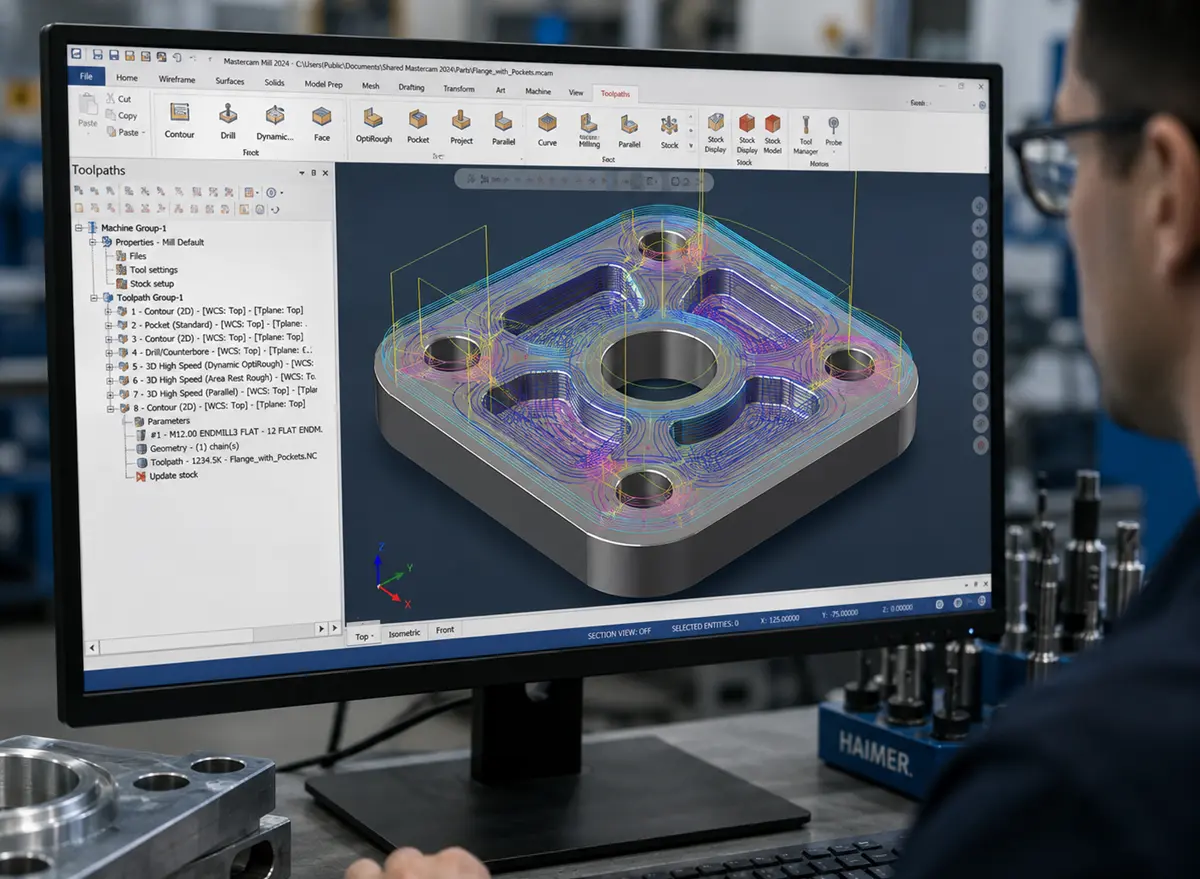
For CNC machining, send STEP as the main CAD model and a PDF drawing for controlled dimensions. Add material grade, finish, quantity, thread specs, heat treatment, surface roughness, and any required inspection report.
A complete CNC quote package should include:
- STEP file for solid geometry
- PDF drawing for tolerances, datums, notes, and critical dimensions
- Material and finish requirements
- Quantity, revision, and target delivery date
- Inspection needs such as CMM report, FAI, Certificate of Conformance, or Material Test Report
3D Printing Quote Files
For 3D printing, send STL when the part is a simple single material print. Send 3MF when the part needs units, colors, textures, materials, build information, or richer additive manufacturing data.
A practical 3D printing quote package should include:
- STL or 3MF file
- Unit confirmation in mm or inch
- Printing process preference, if known
- Material or resin requirement
- Surface finish and post processing needs
- Critical fit dimensions, marked separately if the mesh alone is not enough
Rapid Prototyping Quote Files
Rapid prototyping may need more than one file type when the right process can change after DFM review. Send STEP for CNC prototypes and vacuum casting patterns, STL or 3MF for printed prototypes, and a drawing when fit, tolerance, or material behavior matters.
Mixed projects that move through rapid prototyping services, including CNC prototyping, 3D printing, vacuum casting, and sheet metal prototyping, need a clear decision path. A complete file package helps the supplier compare process cost, lead time, tolerance risk, and part function without guessing.
Critical Dimensions and Assembly Files
Mark critical dimensions outside the CAD model when a dimension affects fit, motion, sealing, load, or inspection. A STEP file shows geometry, but a drawing tells the supplier which dimensions control the part.
For assemblies, send the full assembly STEP file plus separate part files when mating relationships matter. Assembly context helps the supplier check clearance, orientation, datum faces, and stackup risk on robotics components, motion hardware, fixtures, housings, and other parts that must fit into a larger system.
| Manufacturing Need | Quote File Package |
|---|---|
| CNC machined part | STEP plus PDF drawing |
| Tight tolerance feature | STEP plus drawing with datums and tolerances |
| Simple 3D print | STL plus unit and material notes |
| Multi material or color print | 3MF plus print notes |
| Rapid prototype with uncertain process | STEP, STL or 3MF, drawing, quantity, and use case |
| Assembly fit review | Assembly STEP plus part files and critical dimensions |
FAQ
Can You Use STEP Files for 3D Printing?
Yes, STEP files can support 3D printing after meshing. CAD software or slicing software converts STEP geometry into a printable mesh before the printer builds the part. Send STEP when the supplier may need to adjust geometry, check fit, or choose between CNC machining and 3D printing.
Is 3MF Better Than STL for 3D Printing?
3MF is better when the print needs richer additive data. ISO/IEC 25422:2025 defines the 3D Manufacturing Format specification suite, including the core 3MF file format and its extensions. STL is still practical for simple single material prints.
Do STEP Files Store Tolerances Automatically?
No, STEP files do not store tolerances by default. A STEP file can include PMI when the CAD system and export settings support model based definition, but a PDF drawing still helps control tolerances, datums, surface finish, threads, and inspection notes.
Can I Convert STL to STEP for Machining?
You can convert STL to STEP, but conversion does not reliably restore clean CAD intent. The converted STEP may remain a faceted body, which makes machining review harder. For CNC machining, send the native CAD export or rebuild the model as proper solid geometry.
What Happens If the STEP File and Drawing Do Not Match?
The quote can stall when the STEP file and drawing conflict. The supplier should ask which revision controls the order before quoting or machining. Buyers can reduce this risk by naming the controlling file, matching revision numbers, and marking critical dimensions on the drawing.
