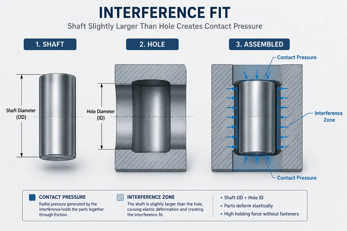

According to ISO 286, an interference fit is a shaft cut larger than its hole. For steel, the overlap is usually just 0.05% to 0.15% of the diameter, yet it locks the two parts by friction, with no bolt or pin.
Whether the fit holds or fails depends on three things: how much overlap you choose, how tightly you machine it, and which materials you pair. Get those right and the joint holds. Get them wrong and the part spins loose or cracks.
How an Interference Fit Works
An interference fit works because the shaft is machined larger than the hole, so assembly forces both parts to deform elastically and press against each other. This contact pressure, combined with friction, resists pull-out and torque. More interference raises the holding force, but it also raises the stress in the outer part.
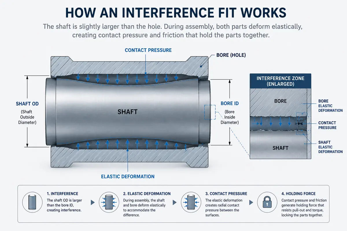
Machined surfaces carry tiny peaks and valleys, so the two parts meet on only about 20% to 40% of the nominal area. Surface finish and roundness then decide how much of the fit actually grips, which is why both carry tight limits on the drawing.
What Are the Types of Interference Fits?
Interference fits divide into press fits and shrink fits, then grade by how much overlap they use.
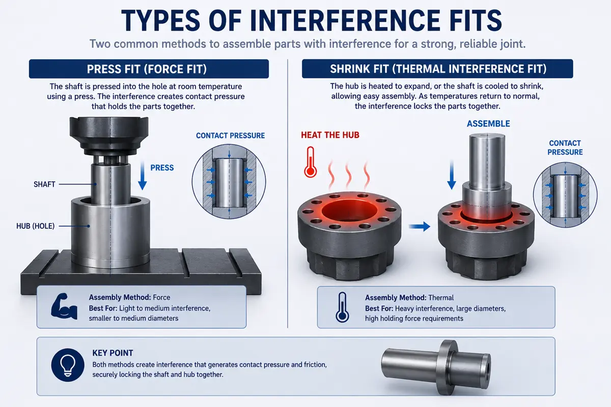
Press Fit (Force Fit)
A press fit, also called a force fit, joins parts at room temperature by pushing the shaft into the hole with an arbor or hydraulic press. This method suits light to medium interference, where the press force stays within equipment limits. A soft mallet can seat very light fits, while heavier overlaps need a press.
Shrink Fit (Thermal Interference Fit)
A shrink fit uses temperature instead of force. Heating the outer part or cooling the inner part opens a temporary clearance, so the parts slide together, then lock as they return to room temperature. Shrink fits handle large diameters and heavy overlaps that are hard to press cold.
Light, Medium, and Heavy Interference Fits
Interference grades scale with load and whether the joint must ever come apart.
- Light fits use the smallest overlap and locate parts that may come apart later for service.
- Medium drive fits add enough grip to hold gears and pulleys against torque.
- Heavy force and shrink fits use the most overlap and lock parts that are not meant to come apart.
Each step up raises both holding force and assembly stress.
How Do Materials Affect an Interference Fit?
Material choice changes the holding force, because stiffness varies by material. A stiffer material like steel builds higher contact pressure for the same overlap, while softer aluminum or brass gives a gentler grip.
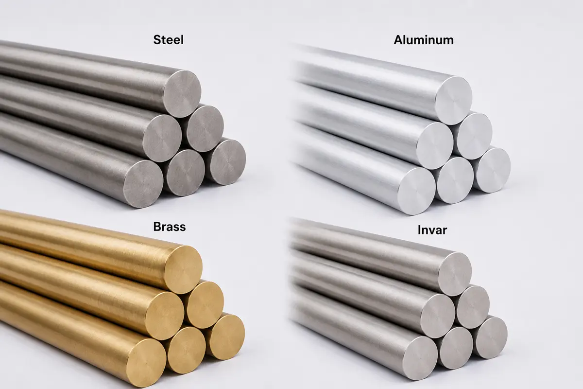
Temperature adds a second effect when the two parts are different metals. A steel shaft in an aluminum hub loosens as the assembly heats up, since aluminum expands about twice as fast as steel. For wide temperature swings, low-expansion alloys such as Invar or Kovar hold the fit more steadily.
How to Machine and Inspect an Interference Fit
An interference fit depends on machining the bore and shaft to tight, repeatable diameters, then verifying them before assembly.
Bore and Shaft Machining
The bore sets the fit, so it gets the most attention. Reaming or precision boring brings the hole to size and roundness after drilling, which holds a tighter diameter than a drill can. The shaft is then turned or ground to match.
A press-fit overlap is only a fraction of a millimeter, so the machining tolerance has to be smaller still. Tolerances near ±0.005 mm on both surfaces keep the fit inside its window, which is routine for precision custom CNC machining parts.
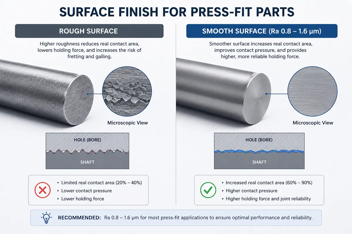
Surface Finish for Press-Fit Parts
Surface finish controls how much of the fit grips. A smoother surface, around Ra 0.8 to 1.6 µm, gives more real contact and a more predictable holding force. A rough surface flattens during assembly, which lowers the effective overlap and can leave the joint weaker than the drawing suggests.
Inspection with CMM and Bore Gauges
Inspection measures the bore and shaft against the drawing before they are pressed together. Bore gauges check hole diameter and roundness, micrometers check the shaft, and a CMM maps both. For buyers comparing suppliers, Rollyu Precision runs in-process and CMM inspection with dimensional reports, so a bad diameter is caught while a fix still costs little.
What Design Rules Prevent Interference Fit Failures?
Three rules prevent most interference-fit failures: add a lead-in chamfer, keep enough wall around the bore, and hold the overlap inside the calculated range.
Lead-In Chamfers
A lead-in chamfer starts the parts straight and prevents galling. A short chamfer of 15 to 30 degrees on the shaft end and the bore mouth lets the shaft enter without shaving metal or jamming off-axis. Skipping the chamfer is a common cause of scored bores and crooked presses. The chamfer vs fillet choice depends on whether the edge guides assembly or spreads stress.
Wall Thickness
The outer part has to carry hoop stress without splitting. Pressing a shaft into a thin-wall hub stretches the wall, and too little material around the bore cracks under that load. A common guide keeps the outer diameter at least 1.5 to 2 times the bore diameter, so the wall can hold the overlap.
Interference Amount
Cracking and galling come from too much overlap or a rough press. Keeping the interference inside the calculated range protects brittle and hardened parts, and a clean, lubricated press lowers galling on stainless and aluminum. Hardened bores resist galling better than soft, as-machined surfaces.
Where Interference Fits Are Used
Interference fits show up across precision machined parts, wherever a component must stay fixed to a shaft or bore without a separate fastener.
Bearings, Bushings, and Dowel Pins
Bearing seats, bushings, and dowel pins are the most common interference-fit features on machined parts. A bearing race presses onto a turned shaft or into a machined housing so it cannot spin, a bushing presses into a reamed bore as a replaceable wear surface, and a dowel pin locates two machined parts in a precise, repeatable position. Choosing among types of bearings starts with the fit each bearing needs.
Gears, Pulleys, and Press-Fit Inserts
Gears and pulleys press onto a machined shaft when the torque is moderate and a keyway would add cost. Press-fit inserts add threads or bearing seats to soft or thin parts, including machined aluminum housings and plastic enclosures. Each of these joints trades easy disassembly for a lower part count.
Medical, Robotics, and Semiconductor Applications
Precision industries rely on interference fits for compact, fastener-free joints. Medical devices use them in surgical handpiece bearings and sensor housings, robotics uses them in gear and actuator assemblies, and semiconductor tools use them in alignment pins and wafer-handling fixtures. These robotics components often combine pressed bearings with tight running clearances in one part.
What’s the Difference Between Interference and Clearance Fits?
The difference is the gap. An interference fit has no gap, so the parts grip on contact. A clearance fit leaves a small gap, so the parts slide or rotate freely.
| Factor | Interference fit | Clearance fit |
|---|---|---|
| Sizing | Shaft larger than hole | Hole larger than shaft |
| Movement | Locked by friction | Slides or rotates |
| Assembly | Press, or heat and cool | Drops in by hand |
| Common use | Bearings, bushings, gears | Bolted joints, sliding pins |
Choose an interference fit when the joint must carry load without a separate fastener. Choose a clearance fit when the parts must move or come apart for service.
When to Choose a Different Joining Method
Choose another joining method when the parts must come apart, carry high torque, or use materials that creep or crack.
- Threaded fasteners and keyed joints handle high torque and frequent service.
- Adhesives and retaining compounds fill loose tolerances and spread load across the joint.
- Snap fit joints flex into place and release without damage, which suits thin plastic parts.
Rollyu Precision’s DFM review checks the material, wall thickness, and tolerance. The review then shows which joint fits the part, before machining starts.
FAQ
How do you calculate the press-fit force for a shaft and hub?
Press-fit force equals the interface pressure times the contact area times the friction coefficient, which runs about 0.1 lubricated to 0.3 for dry steel. More interference, a longer engagement length, or a rougher surface raises it. Engineers size the pressure with Lamé thick-wall cylinder equations or an ISO 286 press-fit calculator.
How do you call out an interference fit on an engineering drawing?
Use an ISO 286 hole-basis callout, such as H7/p6 for a light press, H7/s6 for a medium drive fit, or H7/u6 for a heavy force fit. The ANSI B4.1 equivalents are the FN1 to FN5 force-fit classes. Keep one standard per drawing, since mixing ISO and ANSI causes errors.
Why does a press fit loosen under vibration or at high speed?
Cyclic micro-movements below about 0.01 inch between shaft and hub cause fretting corrosion, which polishes the contact and slowly relaxes the grip. At high rpm, centrifugal force expands the hub and lowers contact pressure. High-speed designs therefore check the fit at operating temperature and speed, not only at rest.
Do press fits in plastic parts loosen over time?
Plastics cold-flow under steady stress, so a press fit that grips on day one can relax within weeks as the material creeps. Keep interference under about 0.1 mm for small plastic parts and use a reamed hole. PEEK and glass-filled grades creep less than unfilled nylon or acetal.
Can an interference fit be taken apart and reused?
Light press fits can be pressed out and reused if the bore still measures in tolerance, but each cycle removes a little material and lowers holding. Shrink fits and heavy force fits usually damage the surfaces on removal. For bearings and safety-critical joints, fit a new part rather than reusing the old one.