
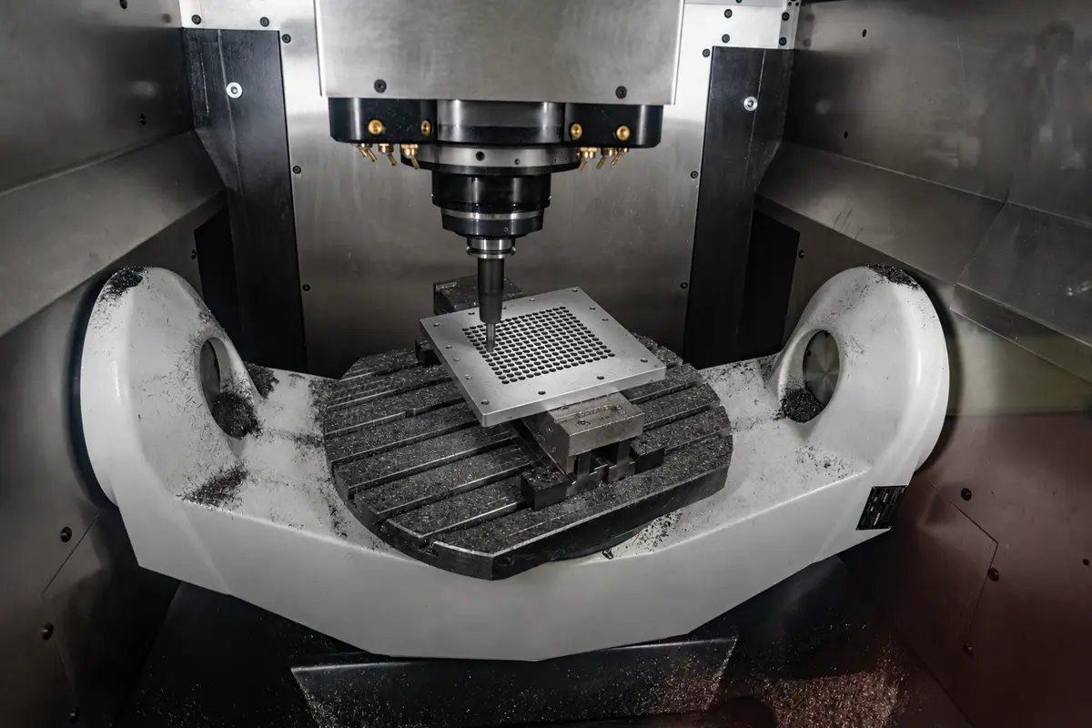

Semiconductor vacuum components need coordinated control of seal geometry, surface condition, burrs, and contamination. A flange may meet its dimensional tolerances and still leak if a tool mark crosses the seal path, the O-ring groove has excessive gland fill, or a burr retains particles.
Define functional datums, surface texture, inspection conditions, and the leak-test boundary before machining. These requirements guide the setup plan, measurement method, cleaning route, and supplier qualification process.
What Must CNC Machining Control in Vacuum Components?
CNC machining must control the complete sealing interface. The mating face, seal contact area, groove, ports, and internal passages work together to control alignment, gas flow, particle risk, and leak-test results.
Flatness at Mating Faces
Flatness helps distribute sealing load across the mating interface. A bowed or twisted face can unload part of an O-ring, change metal-gasket compression, or pull a bolted assembly out of alignment. Set the flatness tolerance from the seal design and flange stiffness, not a shop default. The drawing should also state whether inspection occurs in a free state or under defined restraint. A thin flange may pass while clamped and move after release, so both parties need the same inspection condition.
Surface Texture at Seal Contact Areas
Seal contact areas need a texture that the selected O-ring or gasket can close under the available load. An Ra value alone does not describe deep scratches, chatter, waviness, or machining lay. A tool mark that crosses the seal path can create a gas path even when the reported Ra value passes.
Specify the roughness parameter, measurement direction, permitted defects, and lay direction. Keep cosmetic finish requirements separate from functional seal-face requirements because polishing can round an edge or change groove depth.
O-Ring Groove Geometry
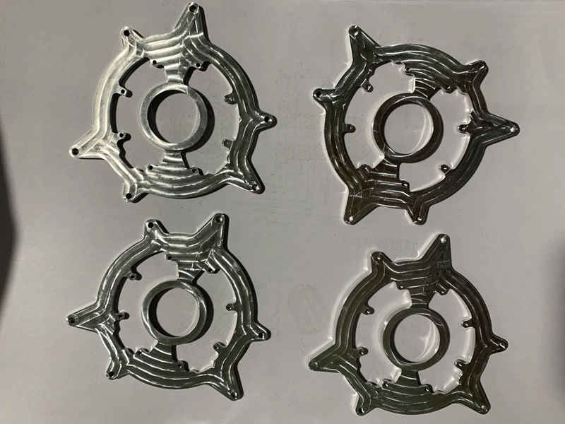
An O-ring groove must produce the intended squeeze without pinching the seal or exceeding the design gland fill. Use the seal manufacturer’s vacuum-gland data and define:
- groove depth and width;
- corner radii and edge break;
- O-ring cross section and material;
- designed squeeze and gland fill;
- surface texture on the groove floor and contact faces;
- allowable mismatch at split lines or intersecting features.
Evaluate these dimensions as one gland design. Reducing groove depth increases squeeze, but it also changes gland fill and assembly force.
Burr Control at Ports and Passages
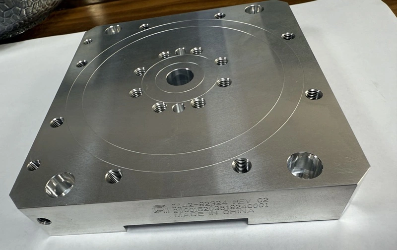
Burrs at ports, cross holes, and threads can break loose during cleaning, assembly, or pump-down. A metal sliver may damage a seal, contaminate a process area, or enter a valve or gas path. Identify inaccessible intersections and set an inspectable edge condition on the drawing. Blind threaded holes may also need vented fasteners or another vent path when trapped gas could slow pump-down. The machining plan should confirm that deburring reaches each specified intersection without enlarging a metering feature or damaging an internal finish.
How Are Critical Vacuum Sealing Features Machined?
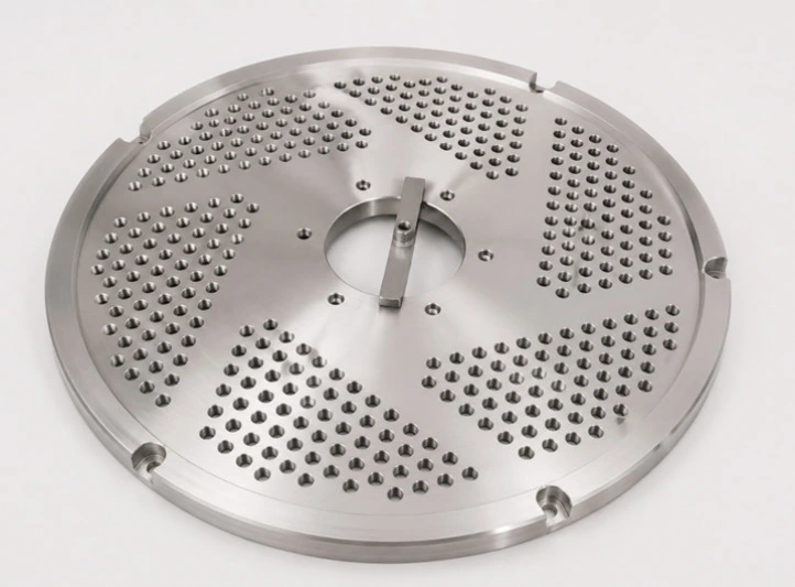
A stable process keeps sealing features tied to the same functional datums through roughing, finishing, deburring, and handling. The setup must also limit distortion after fixture release.
Datum Strategy for Mating Features
Build the datum structure around how the component locates in the vacuum assembly. A functional mating plane may establish the primary reference, while a bore, pilot, or dowel pattern controls radial location and clocking. The shop can then machine and inspect grooves, ports, and fastener holes from the same reference system.
A convenient raw edge should not become the primary datum when the assembly locates elsewhere. If the process needs temporary datums, the setup plan must transfer final features back to the functional datum reference frame without stacking uncontrolled setup error.
Workholding for Thin-Wall Components
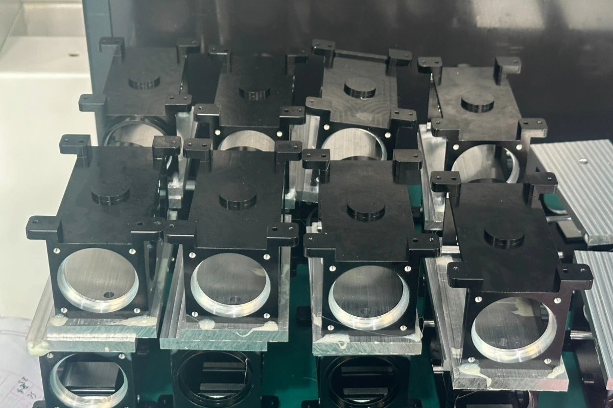
Thin-wall vacuum components need low-distortion support and controlled clamping force. Broad soft jaws, shaped nests, sacrificial supports, or distributed clamps can spread the load near the cut. The fixture should hold the part without forcing it into a shape that disappears after release. If the drawing requires restrained inspection, define the fixture and restraint force so the buyer and supplier measure the same condition.
Roughing and Finish-Machining Sequence
A stable CNC machining process separates heavy stock removal from final seal machining:
- Establish process datums and rough the main cavities, ports, and external form.
- Leave uniform stock on thin walls, mating faces, seal lands, and grooves.
- Let the part stabilize, or apply the specified stress-relief step when the material and drawing require one.
- Re-establish the functional datums, semi-finish critical relationships, and check distortion.
- Finish mating faces and sealing geometry with controlled tools and cutting conditions.
- Deburr specified intersections, clean the component, and inspect it after fixture release.
This sequence is a planning baseline. Material condition, wall thickness, coating allowance, and the required inspection state may change the route.
Protection of Finished Sealing Faces
Protect finished sealing faces as soon as machining and inspection permit. Clean covers, non-shedding separators, and individual packaging reduce contact with chips, fingerprints, and other parts. The protective material must not leave adhesive, fibers, or plasticizer on the vacuum surface. When another facility handles finishing, cleaning, or leak testing, the traveler should record the protection time and authorized removal point.
How Should Engineers Specify and Verify Vacuum Components?
The purchase package should connect each functional requirement to an inspection condition, record, cleaning step, or leak-test criterion. This link prevents a supplier from accepting a feature with a method that does not address its failure mode.
Surface Roughness and Lay Callouts
A useful surface-texture callout states the parameter, limit, lay, and controlled area. Separate the O-ring contact band, groove floor, metal-gasket contact geometry, and general machined surfaces when those areas perform different functions.
The inspection plan should name the instrument and trace direction. A stylus trace taken parallel to the lay may miss grooves that cross the sealing path. Visual criteria should also cover scratches, dents, chatter, embedded debris, and polishing rollover because one roughness value cannot detect every sealing defect.
GD&T for Sealing Features
Geometric dimensioning and tolerancing should control the relationships that the assembled seal uses. Flatness controls one surface without a datum. Parallelism, perpendicularity, profile, position, or runout can connect that surface to a bore, pilot, groove, or opposing face when assembly alignment depends on the relationship.
Avoid duplicate controls that conflict or measure the same error twice. Define the functional datum reference frame, applicable material condition modifiers, and the free-state or restrained inspection condition. Resolve ambiguous GD&T before programming begins.
Dimensional Inspection of Critical Features
Match the inspection method to the feature and acceptance question.
| Feature | Suitable verification approach | Limitation to control |
|---|---|---|
| Mating-face flatness and profile | CMM or calibrated form measurement | Fixture force and point density can hide local or free-state distortion |
| O-ring groove width, depth, and location | CMM, calibrated depth tools, optical measurement, or form tracing | Probe access and tip radius may miss small radii or local damage |
| Surface roughness and lay | Calibrated profilometer plus visual inspection | Trace direction and cutoff settings affect the result |
| Port and passage intersections | Borescope, optical inspection, or another validated method | Line-of-sight inspection may not reach every cross hole |
| Threads and sealing ports | Functional gauges plus dimensional measurement | A thread gauge does not verify burr removal or vacuum tightness |
The report should identify the instrument, measured values, drawing revision, part identity, and inspection condition. A CMM inspection report verifies geometry. It does not prove that the assembled joint meets its leak-rate requirement.
Leak-Test Acceptance Criteria
Write the complete leak-test condition into the quality plan. Define the test method, tracer gas, maximum allowable leak rate and units, pressure differential, test direction, stabilization time, temperature range, covered ports, and background-signal treatment.
The purchase order should also identify the test article. A machined component, capped subassembly, and complete system have different leak boundaries. A machined part without welds or installed seals may receive dimensional and surface acceptance first, followed by helium leak testing after assembly. A leak-rate number without a method and boundary is not a repeatable acceptance criterion.
How Should Buyers Qualify a CNC Supplier for Vacuum Components?
Qualify the supplier against the component’s sealing, cleanliness, and documentation risks. A general CNC capability statement does not show whether a shop can protect seal faces, inspect released thin-wall geometry, or control subcontracted processes. At Rollyu Precision, we review semiconductor CNC machining requirements against the drawing and inspection scope before production planning.
Relevant Part and Process Experience
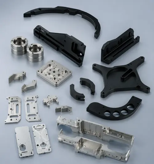
Ask for evidence from parts with comparable materials, wall sections, sealing features, and inspection requirements. Vacuum chamber components, manifolds, precision flanges, valve bodies, and particle-sensitive fixtures may be relevant when the process challenge matches the new part.
For a new or revised part, a first article inspection can verify the datum plan, workholding method, tool access, deburring route, and report format. The first article should include any finishing and release conditions that can change final geometry.
Material and Finish Traceability
The record set should connect the received material to the finished part and each outside process. Depending on the purchase requirements, the record set may include the material grade, heat or lot identity, Material Test Report, Certificate of Conformance, finish specification, processor record, and drawing revision. Control masking with the same precision. Seal lands, threaded grounds, electrical contact areas, and internal vacuum surfaces may need different treatment. Mark each masked area and state whether dimensions apply before or after coating.
Inspection and Reporting Scope
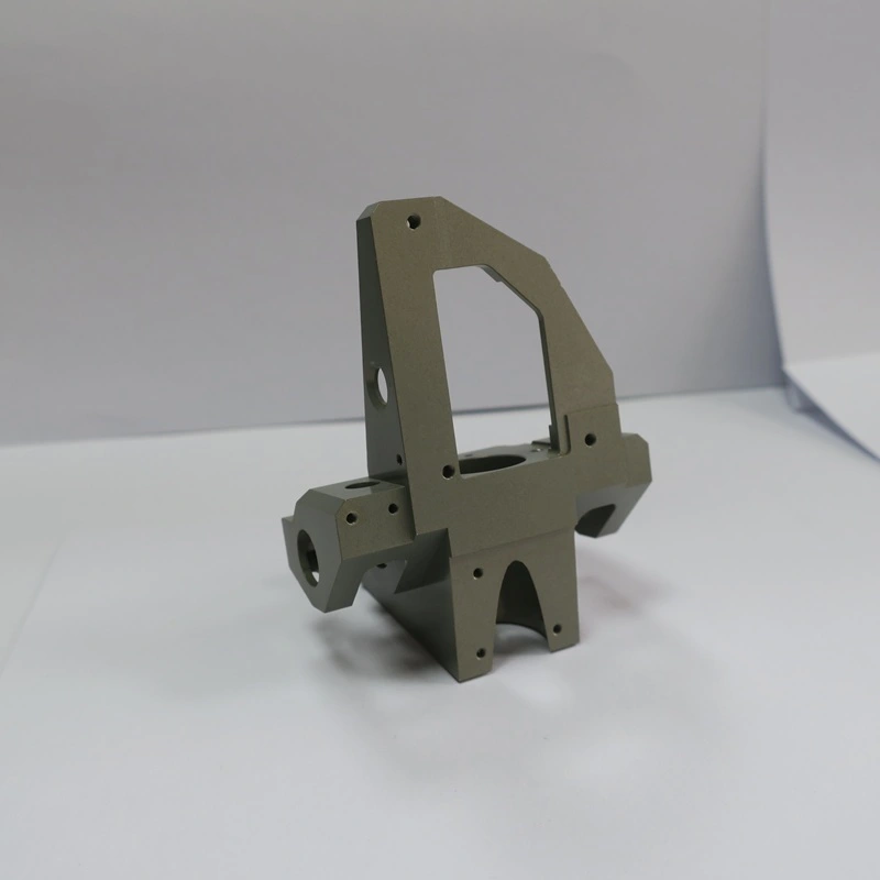
Set the reporting scope before quote approval. Identify ballooned characteristics, critical feature classes, sampling rules, first article requirements, surface-texture records, visual criteria, and any raw measurement data needed for review.
At Rollyu Precision, we support DFM review, CMM inspection, in-process and final dimensional inspection, surface-finish inspection, FAI, dimensional reports, Material Test Reports, Certificates of Conformance, and lot-level traceability. We confirm the exact method, sampling level, and deliverables for each project because a general capability list does not define part acceptance.
Cleaning and Packaging Controls
Define the cleaning process, acceptance condition, packaging method, and responsible party. Ask which chemistry the process uses, whether cleaning solution flows through internal passages, how the process controls rinse residue, and which handling rules apply before bagging.
Packaging should be clean, non-shedding, and compatible with the customer’s vacuum and cleanroom procedure. If the machine shop does not perform final precision cleaning, the routing still needs to protect seal faces and keep shop residue out of blind features before the qualified cleaner receives the parts.
Leak-Testing Responsibility
Assign one owner to each leak-test boundary and procedure. The purchase order or quality plan should name responsibility for fixture design, seal supply, port blanking, calibration, test execution, report review, failure analysis, and retest approval.
| Supply condition | Practical responsibility split |
|---|---|
| Machined component only | Supplier verifies dimensions and surfaces. The buyer or integrator tests the completed sealed assembly unless the order assigns a different scope. |
| Machined and welded subassembly | Supplier may test the defined weld and flange boundary when the buyer approves the equipment and procedure. |
| Complete sealed assembly | One party should control assembly conditions and the final leak test so no boundary falls between machining and integration. |
Leak testing is project specific, so do not infer this service from CNC machining capability. During quote review, we confirm whether the required test is within our agreed scope, assigned to an approved laboratory, or completed after the buyer assembles the component. The quality plan should record that decision before production.
FAQs
How Do O-Ring Seals and Metal Gaskets Change the Machining Requirements?
O-ring seals need controlled gland depth, width, fill, squeeze, and a contact path that will not cut the elastomer. Metal gaskets rely more on contact geometry, surface protection, flange stiffness, and the preload that deforms the gasket. The gasket material and flange specification set the allowed bakeout temperature and surface requirements.
How Is a Virtual Leak Different From a Physical Leak?
A physical leak is a path through a wall, joint, weld, crack, or seal that lets gas enter the vacuum space. A virtual leak comes from gas trapped in blind holes, overlapping joints, deposits, or contaminated surfaces and released during pump-down. Both can slow pressure reduction, but repairing a flange will not remove a trapped internal volume.
Should Aluminum Vacuum Components Be Anodized on Internal Surfaces?
The vacuum-system owner should approve internal anodizing for the process, pressure range, cleaning chemistry, and bakeout temperature. An anodic layer may add wear resistance or electrical isolation, but its pore structure and sealing treatment can affect gas release and contamination. Mask seal contacts, precision fits, grounding points, and knife edges unless the approved drawing states otherwise.
Can a Scratched Vacuum Sealing Face Be Reworked?
Rework is acceptable only when engineering reviews the seal type, scratch direction and depth, remaining material, flatness, and coating condition. Controlled lapping or remachining may recover some elastomer-seal faces. A damaged metal-gasket knife edge may need specialist repair or flange replacement. Inspect the repaired geometry and repeat the specified leak test before release.
Why Do Some Vacuum Components Require Bakeout Before Use?
Bakeout heats compatible vacuum components so adsorbed water and other volatile material leave the surfaces while the pumps remove the released gas. This process can shorten pump-down and reduce outgassing at high or ultrahigh vacuum. The system owner sets the temperature and duration because O-rings, coatings, lubricants, sensors, and dissimilar-material joints may impose lower limits.
