Start a custom optical mount from its function: what it supports, how it locates, and which dimensions control installation. Those answers drive the material choice, the machining strategy, and the inspection plan before the mount reaches production. CNC machining then produces the bores, mounting faces, threads, and bracket features that hold the optic in place, and the surface finish has to suit both the optical assembly and those fits.
What Custom Optical Mounts Need to Control
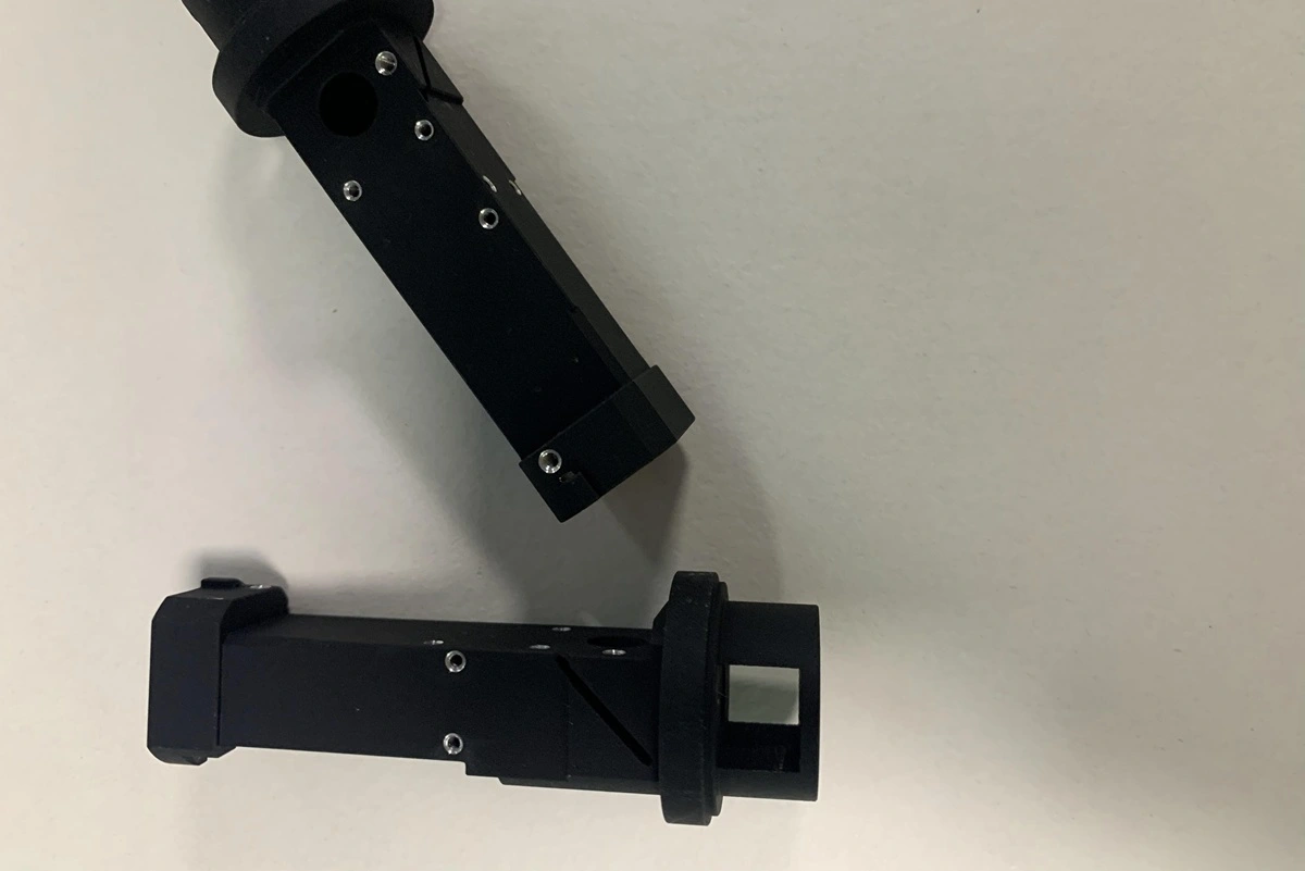
An optical mount holds a lens, mirror, detector, or related assembly in a defined position, and a custom mount adapts that support to a specific instrument, mounting interface, or space envelope. Typical machined parts include lens holders, mirror brackets, mounting rings, baseplates, and alignment fixtures.
On the drawing, separate the surfaces that locate the assembly from clearance features and exterior contours. A lens holder may locate its component in a bore and set its axial position with a shoulder, while a bracket may locate through a mounting face and dowel holes. Those relationships decide how the part sits in the assembly. On an adjustable mount, also mark which features provide movement and which set the fixed reference, so the machining plan protects the locating geometry and leaves the intended adjustment free.
Choosing Materials for Optical Mounts
Choose the material by the mount’s mechanical, thermal, and environmental requirements. Aluminum suits lightweight machined structures, while stainless steel and low-expansion alloys answer other constraints at the cost of more mass and machining effort. Engineering plastics fit some holders, spacers, and alignment blocks, but they are a separate decision with their own stiffness, temperature, and dimensional limits, and a tolerance set for a metal mount doesn’t automatically carry over to a plastic one.
| Material | Reason to Consider It | Engineering Tradeoff | Information to Confirm |
|---|---|---|---|
| 6061 aluminum | Low mass, good machinability, and compatibility with anodizing | Thermal expansion and coating effects still need attention on critical interfaces | Material condition, operating temperature, finish, and final fit |
| Stainless steel, with grade selected for the application | Corrosion resistance and a stiffer material for mounting structures | More mass than aluminum; machining behavior and corrosion resistance vary by grade | Exact grade, environment, surface condition, and machining requirements |
| Invar 36 | Low thermal expansion for temperature-sensitive mounting structures | Specialized machining and material control; low expansion alone doesn’t make the assembly stable | Temperature range, material condition, mating materials, and inspection conditions |
For aluminum mounts, decide the finish along with the alloy. A close-fitting bore and a black exterior may need different treatment boundaries, and leaving that decision until after machining can put the machined dimensions out of step with the finished fit.
Invar machining makes sense when thermal movement is a defined design constraint. Invar’s low expansion limits temperature-driven dimensional change in the mount itself, but the geometry and mating components still shape how the assembly behaves thermally. Look at the whole mounting arrangement before swapping aluminum for a low-expansion alloy.
CNC Features That Control Fit and Position
The hardest features on an optical mount are often the interfaces between otherwise simple shapes. Tie each one to the drawing’s datum structure, tool access, and inspection method during the manufacturing review.
Datum Faces and Locating Features
Datums set the reference system used to define and inspect the part. Choose the mounting face, locating bore, or other features that represent the installed condition, then relate the critical holes and surfaces to them, since a hole diameter alone doesn’t say where the hole sits relative to the mounting face. Flatness, parallelism, perpendicularity, and position each control a different relationship, so apply only the controls and values the assembly needs. Tightening every dimension to the same limit adds machining and inspection work without showing which features actually control the assembly.
Bores, Shoulders, and Threads
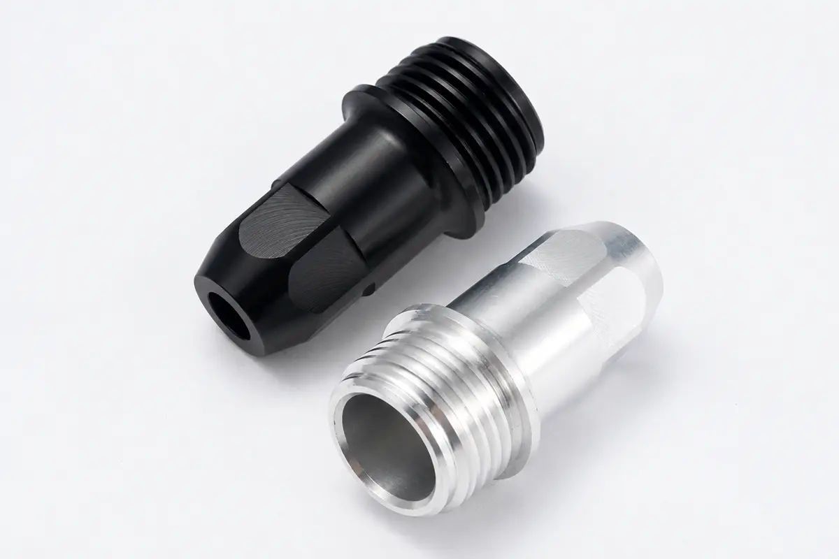
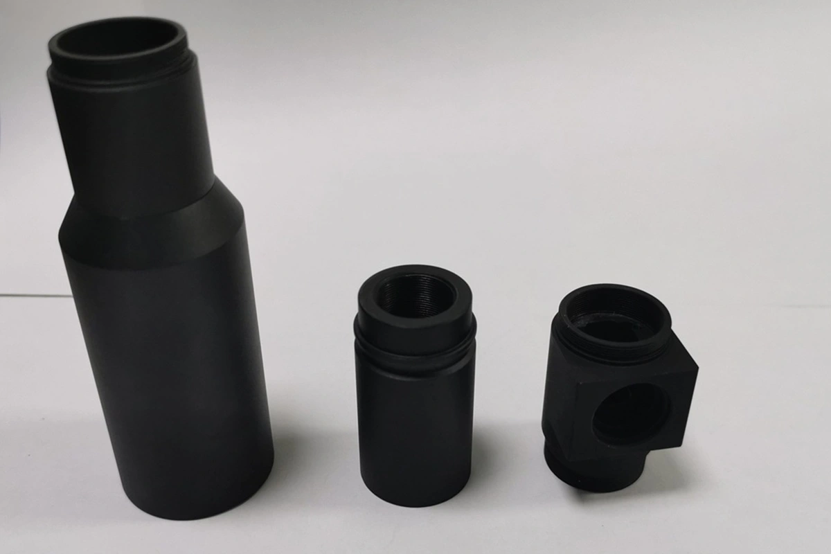
In a lens holder, the bore controls the fit, the seating shoulder sets the axial location, and the retaining thread holds or connects the assembly. Specify each feature for its job, including thread size and fit where applicable. When these features get coated, state the finished condition explicitly, because burrs, coating buildup, or an unclear masking boundary can keep the optic from seating or the thread from assembling. Plan access for deburring and inspection during the feature review, especially around recessed shoulders and internal threads.
Thin Walls and Tool Access
Thin rings and tall, unsupported walls can deflect under cutting or clamping forces. Deep pockets limit cutter reach, and round end mills leave a radius in internal corners, so these features shape how the machinist holds and cuts the mount.
Use the DFM review to check whether a thicker local section, a clampable surface, or a larger internal radius keeps the function while simplifying production. Where a thin or sharp feature is genuinely needed, keep it on the drawing and agree on how it will be made. Set local wall thickness and corner geometry through that part-specific review rather than a generic rule.
Surface Finishes for Optical Mounts
Specify each surface finish by its job: protection, fit, appearance, or optical behavior. Black anodizing is common on aluminum optical hardware, but a black appearance doesn’t prove a measured low-reflectance surface.
- Stray-light control: define the wavelength range, measurement conditions, and acceptance criteria for the surfaces involved. Decorative black and optical black need different acceptance criteria, and only a defined target gives the finisher something to test against.
- Coated fits: black anodized aluminum needs dimensional planning, because the anodic layer changes the finished surface. Give close-fitting bores, threads, and locating faces a clear coating or masking decision, and state which dimensions apply after finishing.
- Local texture: a cosmetic exterior, an optical-facing cavity, and a seating face can each need a different requirement within the same mount. Separate callouts let manufacturing and inspection handle each one directly.
How Rollyu Precision Manufactures Custom Optical Mounts
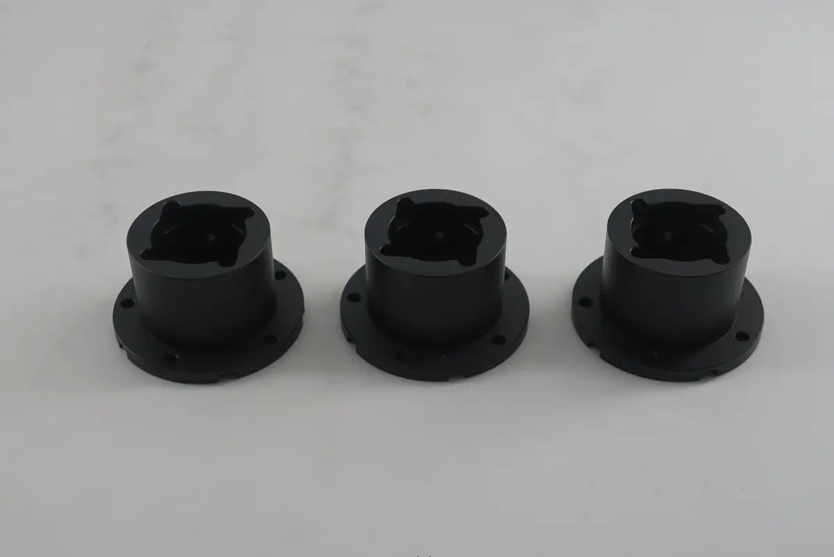
Rollyu Precision machines custom optical mounts and related photonics hardware for prototypes and production runs, with DFM review, surface finishing, and dimensional inspection in the same workflow.
Photonics Part Experience and DFM Review
For photonics and quantum applications, Rollyu machines lens holders, mirror mounts, beam-steering assemblies, alignment fixtures, and other optical mounts. Use the engineering review before machining to raise thin walls, difficult pockets, internal corners, and other features that affect manufacturability. On a custom mount, bring the locating interfaces and finish boundaries into the same discussion so engineers can check any proposed change against the assembly’s function.
Milling and Turning for the Part Geometry
Rollyu’s CNC machining range covers 3-, 4-, and 5-axis machining plus CNC turning. Milling produces faces, pockets, slots, and mounting patterns, and turning produces cylindrical features such as rings, tubes, and round holders. Pick the process by the geometry and access the specified features need.
Multi-axis machining helps when features sit on several faces or need angled access, but the process review still has to settle workholding, reference features, and machining sequence for the actual part. Machine capability doesn’t replace a drawing-specific process plan.
Inspection and Manufacturing Records
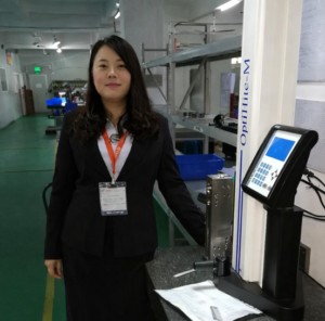
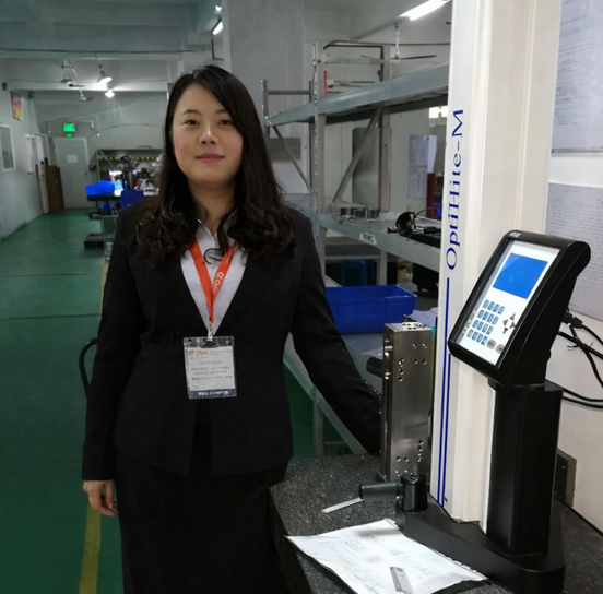
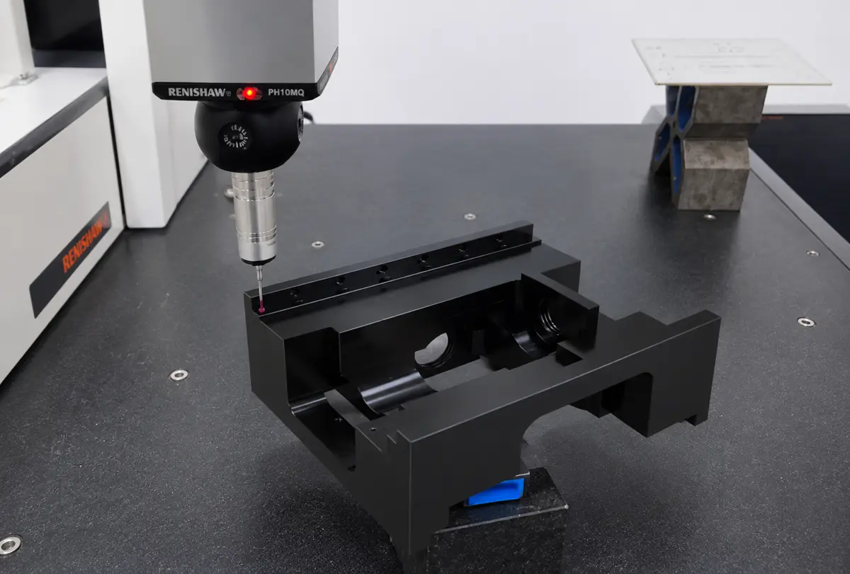
Rollyu’s inspection equipment includes CMMs, micrometers, bore gauges, thread gauges, and surface roughness testers. CMM inspection covers dimensional and geometric relationships, and the other instruments cover the features and characteristics assigned to them.
For sourcing teams and supplier quality engineers, Rollyu also supports first article inspection, dimensional reports, Material Test Reports, Certificates of Conformance, and lot-level traceability. Agree on the records and inspected characteristics before production so the documentation matches the part’s acceptance requirements.
Preparing an Optical Mount for Quotation
Send Rollyu Precision a 3D model and the drawing information that defines the finished part:
- Material grade and condition
- Critical tolerances, datum references, and thread requirements
- Surface finish and masking boundaries
- Prototype and production quantities, requested inspection records, and target delivery schedule
For a temperature-sensitive or vacuum application, state the operating requirements in the inquiry so the engineering team can review the proposed material and process scope. Ask for DFM feedback on the locating features and difficult geometry before releasing the design for machining.
Frequently Asked Questions
Can a Standard Optical Mount Be Modified?
Yes, if the original manufacturer supports the modification. Some optical suppliers modify catalog mounts for nonstandard optics or mounting interfaces, which keeps a useful standard mechanism while changing the interface your instrument needs. Ask that supplier to review the change before anyone machines the existing hardware.
Are Black-Anodized Optical Mounts Automatically Vacuum-Compatible?
No. Vacuum compatibility needs an application-specific specification, and the finishing process, lubricants, cleaning, and handling can matter alongside the base material. State the operating pressure and temperature, then confirm the applicable manufacturing and qualification scope. A black color is no evidence that the finished mount meets those requirements.
Does a CMM Report Prove Optical Alignment?
No. A CMM report verifies the measured mechanical geometry against the specified requirements. It doesn’t establish the assembled system’s beam position, angular stability, or optical performance, which need an optical alignment or functional test defined separately from the mount’s dimensional inspection.