
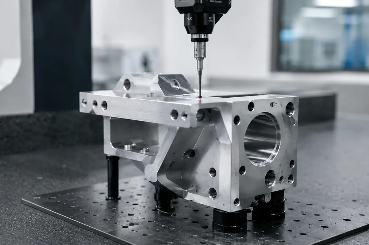

Choose the metal rapid prototyping process that can reproduce the features, material behavior, and operating conditions behind the next design decision. CNC machining suits tight features in specified stock alloys. Metal 3D printing suits internal channels and consolidated geometry. Sheet metal fabrication suits formed housings, brackets, panels, and frames.
The drawing does not make that choice by itself. The test plan must state what the prototype needs to prove, which results must transfer to production, and what evidence the supplier must deliver.
What Should a Metal Prototype Prove Before Process Commitment?
A metal prototype should answer a defined engineering question before the OEM team commits to production tooling, fixtures, or a manufacturing route. Appearance alone does not prove fit, function, or production feasibility.
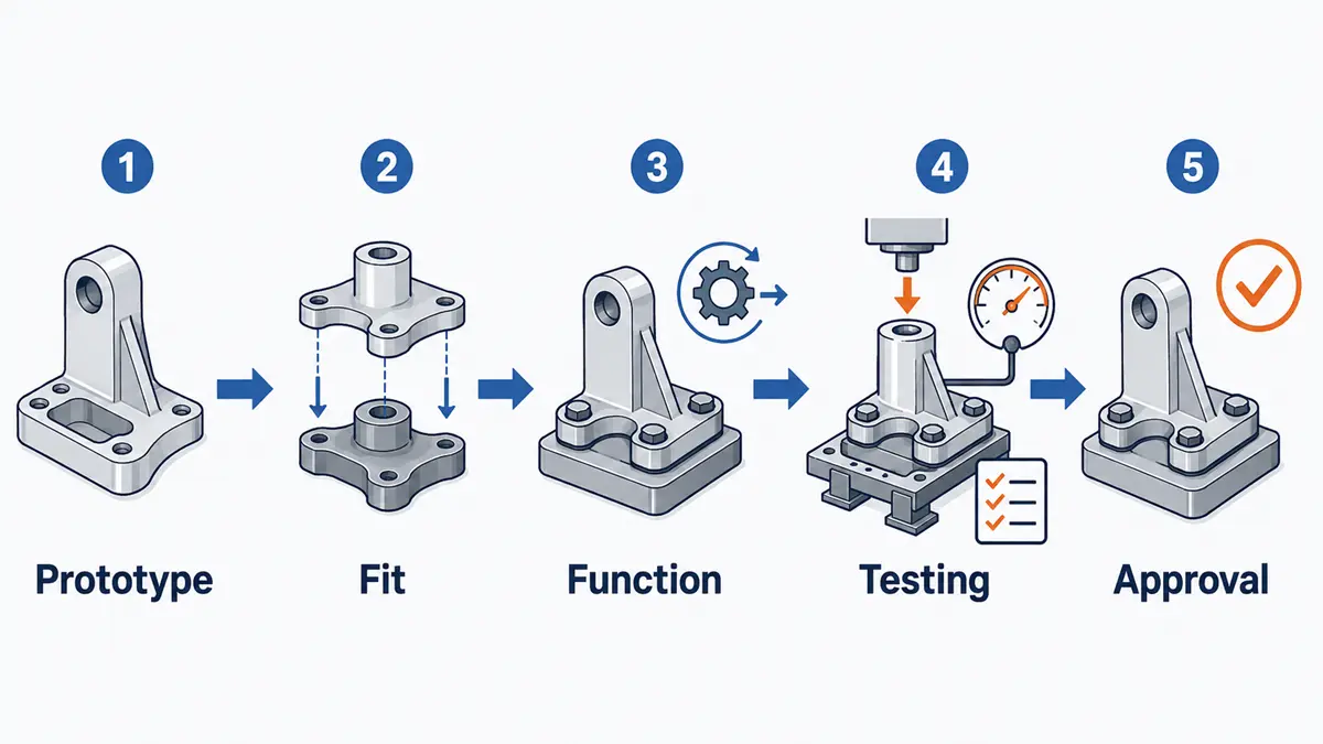
Fit, Clearance, and Assembly Checks
Use the prototype to confirm that mating parts assemble without hand fitting, interference, or uncontrolled movement. Mark the functional datums, hole patterns, threads, connector locations, and mating surfaces on the drawing. Then build the assembly with the planned fasteners, bearings, seals, inserts, and cables. This test can expose tolerance stack problems that a single-part inspection report will miss. Record the assembly sequence and any adjustment so engineers can trace a failure to the design, the process, or the build method.
Operating Conditions and Functional Tests
Reproduce the loads and conditions that could change the design decision. Depending on the part, the test may cover pressure, temperature, vibration, fluid exposure, grounding, wear, or repeated assembly.
The prototype must preserve the property under test. A different alloy, heat treatment, wall structure, or surface condition can make a result unsuitable for material approval. When the first build checks only envelope and access, classify it as a form-and-fit prototype. Do not use that result as functional proof.
Design Verification Before Route Selection
Define the verification question before selecting the process. Requirements that affect approval must represent production, including the material grade, critical dimensions, loaded interfaces, sealing faces, and thermal paths. A simplified feature, noncritical finish, or cosmetic color can act as a proxy only when it does not change the test result. Leave production tooling details, cycle-time work, and automation features for process development because a prototype cannot validate them. This split directs inspection toward the features that control the decision.
How Do Part Requirements Affect the Process Choice?
Geometry, material, tolerance, quantity, and required records narrow the viable process before price does. Review these requirements together because a low quote has little value when the proposed route cannot produce valid test evidence.
Geometry, Size, and Tool Access
Check whether a cutting tool, forming tool, or additive build can create the geometry without compromising the features under review. CNC machining needs tool access and secure workholding. Deep narrow pockets, small internal radii, and features on different faces can increase setup time or require a design change.
Metal 3D printing can create internal passages and consolidated forms that a cutter cannot reach, but the build still needs support removal and access for secondary machining. Sheet metal fabrication suits parts made from a consistent gauge with bends, tabs, seams, or formed features. Block-like parts and large thickness changes usually point to another route.
Material and Functional Test Requirements
Name the required material grade and condition when stiffness, corrosion exposure, conductivity, fatigue behavior, or heat treatment affects approval. Do not accept “equivalent metal” unless engineering has defined which properties may differ. Wrought, printed, and cast forms of a nominal alloy can have different process histories and internal structures. Treat a cross-process test as directional unless the approved test plan permits that substitution.
Tolerance, Surface Finish, and Critical Features
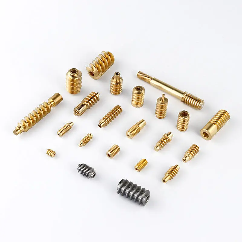
Apply tight tolerances only where function requires them. Datums, bearing seats, sealing faces, bores, threads, and mating interfaces often deserve closer control. Wider limits on noncritical surfaces can reduce setups and inspection work without weakening the test.
Surface finish can affect sealing, sliding wear, coating adhesion, optical mounting, and cosmetic approval. Define the measurement method or visual standard when finish affects acceptance. If machined interfaces control assembly, confirm that the supplier’s CNC machining parts capability covers the feature, datum scheme, and inspection method.
Quantity, Lead Time, and Cost
Quantity changes which setup cost matters. CNC machining can suit one part or a small functional batch when stock and tooling are available. Metal 3D printing can reduce part count for complex geometry, although build preparation and post-processing still affect the quote. Sheet metal becomes more practical when parts share the same gauge, bend logic, and hardware. Compare setup, material, machine time, secondary operations, finishing, and inspection as separate cost drivers. The route comparison in 3D printing vs CNC machining shows why two quotes may price different forms of evidence even when both suppliers receive the same CAD model.
Inspection, Traceability, and Documentation
Match the inspection package to the decision risk. A basic fit check may need results for a short list of critical dimensions. An OEM quality plan may also call for First Article Inspection results, a Certificate of Conformance, a Material Test Report, surface finish measurements, or lot-level material traceability.
The RFQ should name the measured characteristics, method, sampling scope, and required record. The word “inspected” does not define acceptance evidence.
Which Metal Rapid Prototyping Processes Should OEM Teams Compare?
Compare CNC prototyping, metal 3D printing, sheet metal prototyping, and mixed routes against the same test plan. Each route controls some requirements better than others.
| Process | Strong fit | Main design constraint | Common follow-up work | Evidence the process can provide |
|---|---|---|---|---|
| CNC prototyping | Tight interfaces, accessible features, and specified stock alloys | Tool access, workholding, internal corner radius, and setup count | Deburring, finishing, heat treatment, and inspection | Fit, tolerance, finish, and material-based functional results |
| Metal 3D printing | Internal channels, lattice structures, consolidated parts, and complex forms | Build orientation, supports, thermal distortion, and minimum feature limits | Support removal, heat treatment, finishing, and critical-feature machining | Geometry feasibility and functional results for complex metal forms |
| Sheet metal prototyping | Brackets, covers, panels, frames, and enclosures | Available gauge, bend radius, flange length, bend access, and springback | Welding, hardware insertion, deburring, coating, and inspection | Form, enclosure fit, assembly access, and fabricated structure checks |
| Mixed process | Near-net or fabricated geometry with tight mating features | Datum transfer and machining allowance between operations | Secondary CNC machining, joining, finishing, and final inspection | Complex geometry with controlled functional interfaces |
CNC Prototyping for Tight Features and End-Use Materials
CNC prototyping fits tests that depend on a specified wrought alloy, accurate mating features, or a controlled surface. Cutting the part from solid stock lets engineers evaluate bores, threads, datums, sealing faces, and assembly interfaces in the required material. Tool access still sets limits. Sharp internal corners, deep pockets, thin walls, and repeated repositioning may require a design change or another route. A CNC prototype machining review should address workholding, cutter reach, setup count, and inspection access before design release.
Metal 3D Printing for Complex Geometries
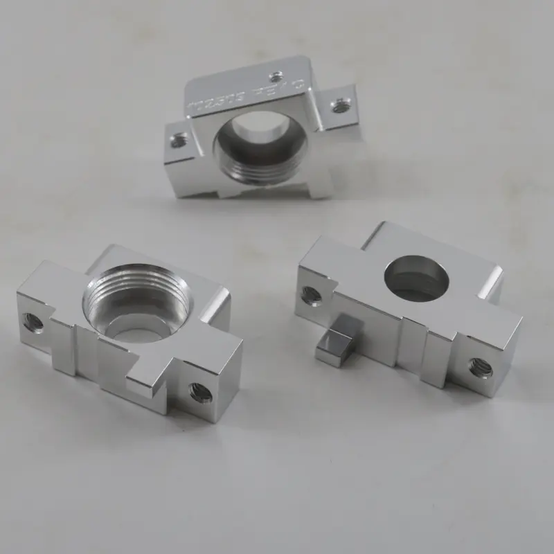
Metal 3D printing fits internal channels, consolidated assemblies, and geometry that would require extensive material removal or multiple machined parts. Before approving the route, review build orientation, support placement, thermal distortion, surface condition, and post-build treatment.
Printed holes and surfaces may need secondary machining. Add machining allowance to sealing faces, precision bores, threads, and datum surfaces when those features require tighter control. The drawing should distinguish as-printed features from machined features.
Sheet Metal Prototyping for Housings and Brackets
Sheet metal prototyping fits enclosures, guards, brackets, trays, panels, and light frames made from a consistent material gauge. Test bend direction, flange clearance, hardware access, weld location, and the installed position of connected parts. Springback, bend radius, grain direction, and coating thickness can shift finished geometry, so dimension critical formed features from functional datums and state whether inspection occurs before or after coating.
Mixed Processes and Secondary CNC Operations
Use a mixed route when one process creates the main form and another controls the critical features. A printed blank can receive machined sealing faces. A fabricated enclosure can use machined datum blocks or inserts.
Define machining allowance, locating datums, inspection stages, and ownership at each handoff. Rollyu rapid prototyping services cover CNC prototyping, metal 3D printing, and sheet metal prototyping, so the DFM review can compare these routes against one test plan. Final inspection should cover the completed part, not only the intermediate blank.
What Should an OEM Metal Prototype RFQ Include?
An OEM metal prototype RFQ should identify the design revision, test purpose, acceptance criteria, and required records. That scope lets suppliers quote the same job and exposes technical differences before the buyer issues a purchase order.
CAD Files, 2D Drawings, and Revision Status
Send a controlled file package:
- A native or neutral 3D CAD file that defines the geometry
- A 2D drawing that identifies datums, tolerances, threads, finishes, notes, and inspection requirements
- An RFQ that uses the same revision as the CAD file and drawing title block
An STL mesh does not carry full drawing intent. A STEP vs STL file comparison can help the team select a useful geometry file, but the 2D drawing should control requirements that the model does not define.
Critical Dimensions, Test Conditions, and Acceptance Criteria
Mark the features that can pass or fail the prototype decision. Include the mating condition, load, pressure, temperature, cycle count, or environmental exposure when those factors affect the process or material choice.
Use measurable acceptance criteria. Replace “good fit” with an approved clearance, assembly force, leak limit, or gauge when engineering has defined one. If a limit remains open, identify it as a test objective instead of presenting it as a released requirement.
Material, Quantity, Finish, and Delivery Requirements
Specify the material grade and condition, quantity, finish, protected surfaces, and delivery location. State whether the order covers one design, multiple variants, or a test batch. Separate the required delivery date from the preferred date because an urgent schedule may change material availability, process choice, or inspection scope. Require the supplier to disclose any substitution or limitation.
Supplier Assumptions and DFM Feedback
Require the supplier to state its assumptions and excluded operations, disclose any material or process substitution, and list open technical questions. Each DFM proposal should identify the affected feature and explain how the change would affect function, cost, lead time, or inspection.
When OEM teams compare a precision manufacturing partner, they should test each supplier’s controls against the drawing risk and test plan. Rollyu Precision supports DFM review, CMM inspection, material traceability, and manufacturing documentation. Those controls matter only when the quote defines how they apply to the prototype.
FAQs
Can OEM Teams Request a Quote Before a Metal Prototype Design Is Final?
Yes. Mark the files as preliminary, identify unresolved features, and request a budgetary quote based on stated assumptions. Ask for a final quote after engineering releases the revision and acceptance criteria.
What Can Change Between a Metal Prototype and the Planned Production Process?
Tooling, fixtures, stock form, joining methods, inspection sampling, and some process allowances may change before production. These changes can affect dimensions, material behavior, or appearance. Document which prototype results transfer to production and which need confirmation during the pilot build.
How Should OEM Teams Compare Metal Prototype Quotes from Different Suppliers?
Compare the process route, material condition, included operations, inspection records, assumptions, and delivery basis before comparing total price. Normalize excluded items such as heat treatment, coating, hardware, shipping, and dimensional reports so every quote covers the same acceptance scope.
Should OEM Teams Sign an NDA Before Sending CAD Files?
An NDA may be appropriate when CAD files contain confidential geometry, product architecture, or unreleased program information. Follow the OEM team’s legal and procurement policy. That policy should define permitted recipients, file-handling rules, and retention requirements before the team shares sensitive files.
When Should a Project Move from Metal Prototyping to a Pilot Build?
Move to a pilot build after the design revision, material, critical features, and functional tests are stable enough to evaluate the planned production controls. The pilot should test repeatability, fixtures, inspection flow, secondary operations, and documentation across a small controlled batch.
