

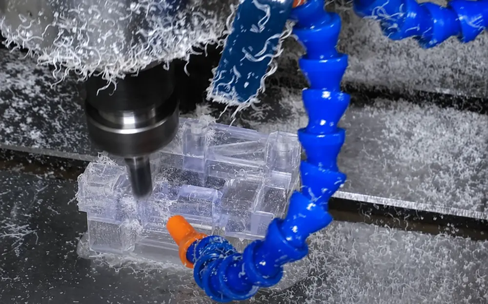
Polycarbonate can be CNC milled, turned, drilled, routed, threaded, and polished with good results, but heat, chip evacuation, residual stress, clamping pressure, and chemical compatibility must be controlled. Sharp tools and a correct chip load are more important than copying one fixed RPM from the internet.
Polycarbonate (PC) is a strong, transparent engineering thermoplastic that can be CNC milled, turned, drilled, routed, threaded, and polished. Its machinability is generally good, but the process window is different from aluminum or steel: the main risks are frictional heat, chip recutting, residual stress, clamping distortion, surface scratching, and stress cracking from incompatible chemicals. The most reliable strategy is to use sharp tools with generous chip clearance, keep the cutter cutting rather than rubbing, evacuate chips quickly, support the workpiece without over-clamping, and treat optical finishing as a separate process requirement.
For buyers, the practical question is not simply “Can polycarbonate be machined?” It is whether the selected PC grade, geometry, tolerance, surface requirement, and assembly environment can be manufactured without melting, whitening, warping, cracking, or losing transparency. The sections below answer those questions first, then show two real drawing-and-part cases.
| Engineer or Buyer Question | Engineering Answer |
| Machinability | Good, provided heat, chips, residual stress and workholding are controlled. |
| Hardness | Grade/test-method dependent. Do not publish one number as universal PC hardness. |
| Heat treatment | No hardening treatment. Stress-relief annealing may be used when the geometry/process justifies it. |
| Cutting speed | Do not specify RPM alone. Calculate from surface speed and cutter diameter; pair it with chip load/feed. |
| Tooling | Sharp carbide is a strong production default; sharp HSS is also viable for some operations. Favor chip space and positive cutting action. |
| Optical finish | As-machined clear PC can show tool marks. Define polishing/clarity only on the surfaces that require it. |
Is Polycarbonate Easy to Machine?
Polycarbonate has good machinability when the cutting edge is sharp and heat is controlled. Compared with brittle clear plastics, PC is tough and impact resistant, so it is less prone to sudden edge chipping. At the same time, it is an amorphous thermoplastic with relatively low thermal conductivity. Heat generated at the cutting edge does not leave the cutting zone as efficiently as it does in metals.
That creates a common failure mode: a tool that is technically “cutting” may begin to rub, the chip softens, material adheres to the cutter, and the edge becomes cloudy or smeared. The added buildup then generates still more heat. Once this cycle starts, continuing with the same parameters usually makes the finish worse.
Good polycarbonate machining therefore depends heavily on chip formation. A healthy process creates a clean chip and carries heat away with that chip. A poor process creates dust, stringy recut chips, or softened material at the edge. The operator should watch the chip, cutter condition, sound, and surface – not RPM alone.
Polycarbonate Hardness: Use Grade-Specific Data, Not One Universal Number
“Polycarbonate hardness” is a useful search term, but there is no single hardness value that applies to every PC grade. Unfilled, UV-stabilized, flame-retardant, optical, medical, and glass-filled grades can have different property data and different machining behavior.
| Representative Material | Hardness Value | Test Method | Use in This Article |
| Ensinger TECANAT natural | Shore D 82 | DIN EN ISO 868 | Example only – verify the ordered grade |
| Covestro Makrolon 3106 | 111 N/mm² ball indentation | ISO 2039-1 | Example only – not interchangeable with Shore D |
These supplier examples demonstrate why hardness should be reported together with the test method and exact grade. They should not be copied into a purchase specification for an unknown “PC” material. For machining, hardness is also not the main process limiter. Cutter geometry, edge sharpness, heat input, chip evacuation, residual stress, and workholding usually matter more than a single hardness number.
Heat Resistance, Glass Transition and the “Melting Point” Question
Polycarbonate is amorphous, so the phrase “melting point of polycarbonate” can be misleading. Unlike a semi-crystalline polymer with a distinct crystalline melting temperature, PC is better described by glass-transition temperature (Tg), heat-deflection temperature (HDT), Vicat softening temperature, and grade-specific service temperature.
Representative unfilled PC data place Tg at about 149-150°C. That does not mean machining is safe until the cutting zone reaches 149°C. Local rubbing can soften and smear a surface well before the entire part approaches Tg, especially on a small tool, deep hole, thin wall, or poorly evacuated pocket. For CNC planning, “keep the cutting zone cool enough to maintain a clean chip” is more useful than designing around a nominal melting-point number.
Does Polycarbonate Need Heat Treatment?
Polycarbonate is not heat treated to harden it like steel. When heat treatment is used, it is normally stress-relief annealing.
Semi-finished plastic stock can contain residual stress from extrusion, molding, cooling, or prior fabrication. Machining removes material that was helping to balance those stresses. A thin, asymmetric, pocketed, or heavily machined component can therefore move after roughing even if the machine itself is accurate.
Stress-relief annealing can be considered when:
- the part has thin or asymmetric walls;
- a large percentage of stock will be removed;
- narrow tolerances must remain stable after unclamping;
- the part will later be polished, coated, solvent-exposed, or assembled under load;
- test machining shows delayed distortion, crazing, or cracking.
The annealing temperature and soak/cooling cycle should come from the exact stock/resin supplier or a validated shop procedure. Publishing one universal annealing temperature for every PC grade is professionally risky. For critical parts, rough machining, stress relief when justified, thermal stabilization, and finish machining can be more reliable than trying to hold final size in one aggressive operation.
Cutting Speed, Feed and Tooling for CNC Machining Polycarbonate
The most important correction to many online “speed charts” is this: RPM is not cutting speed. A statement such as “machine PC at 3,000 RPM” is incomplete unless the cutter diameter is known. Feed rate is also incomplete unless flute count and chip load are known.
| USE SPEED AND CHIP LOAD TOGETHER
Spindle speed (rpm) = [1000 x cutting speed (m/min)] / [pi x cutter diameter (mm)] |
The practical goal is to produce a chip thick enough to shear cleanly and carry heat away, without overloading the edge or deflecting the workpiece. Excessive RPM combined with a low feed can make the tool rub and melt the surface. Excessive feed can overload a thin wall or leave a coarse finish. The correct pair depends on cutter diameter, flute geometry, engagement, machine rigidity, PC grade, workholding, and finish requirement.
For CNC routing with purpose-designed router tooling, LMT Onsrud reports an optimum chip-load range of roughly 0.004-0.012 in. (0.10-0.30 mm) for polycarbonate/soft-plastic routing. That is useful evidence that chip load matters, but it is not a universal milling specification for every small end mill. The safest B2B engineering rule is to start from the cutter manufacturer’s plastic-specific data and validate the result on the actual grade and geometry.
Tooling: Sharp Edges and Chip Space Matter More Than “Hardest Tool Wins”
Sharp carbide tooling is a strong default for production CNC machining because it holds an edge well. HSS can also work, especially for drilling, when it is sharp and has suitable geometry. For routed sheet and pockets, polished single-flute or two-flute cutters are often effective because they provide generous chip space. Ensinger likewise recommends tools with adequate chip clearance and notes the benefits of single-cutter tools for thermoplastics.
Useful tooling principles include:
- sharp, smooth cutting edges;
- positive, cutting geometry rather than a scraping edge;
- generous flute space for chip evacuation;
- one or two flutes where chip clearance is critical;
- minimal tool runout;
- a short, rigid tool projection;
- a finishing tool that is not already carrying melted PC on the flute.
A fresh, correctly shaped tool often improves surface quality more than simply lowering the speed.
CNC Milling and Routing
During milling, maintain a stable engagement and avoid dwell. Ramp or enter from an open edge when possible instead of plunging a flat-bottom router tool directly into transparent sheet. Onsrud notes that ramp entry provides a chip escape path and can reduce chip wrap, melting, and stress-related defects.
Thin sheet needs continuous support. Vacuum fixtures, spoilboards, soft jaws, or broad low-pressure clamps are preferable to a few high-force clamp points that can bow the panel. If a large clear guard is visibly flat while clamped but springs out of tolerance after release, the problem may be fixturing stress rather than machine accuracy.
For thin-wall housings or deep pockets, rough in balanced stages and leave a controlled finish allowance. Removing a large amount of material from one side of stressed stock can release stress asymmetrically.
Drilling Polycarbonate
Drilling concentrates heat inside the hole, where chips are harder to remove. Use a sharp drill, controlled feed, adequate backing/support, and peck or intermittent withdrawal when depth demands it. Ensinger specifically emphasizes frequent drill withdrawal for chip removal and cooling and warns that plastic’s insulating behavior can create rapid heat buildup.
For holes close to an edge, thin walls, or transparent cosmetic areas, inspect for whitening or micro-cracking. For critical holes, consider interpolation or a staged drill/finish process rather than forcing a dull tool through the material. Threaded holes deserve the same heat-control discipline because tapping creates friction and local stress.
Turning Polycarbonate
Polycarbonate rod and tube can be turned successfully with a sharp tool, small nose radius where appropriate, stable support, and a continuous chip-removal strategy. Long slender parts may require additional support because PC is much less rigid than metal. The finishing pass should cut cleanly rather than skim with a dull edge, which can polish by friction and create heat instead of producing a controlled surface.
Cooling, Chip Evacuation and Chemical Compatibility
Compressed air is often valuable because it cools the cutter and removes chips at the same time. Dry machining can also reduce the risk of chemical interaction. When liquid coolant is required, compatibility with the exact PC grade should be confirmed. Amorphous plastics can be sensitive to stress cracking from certain oils, solvents, cleaners, or cutting fluids – especially when the part already contains residual or assembly stress.
A coolant that works on aluminum is not automatically safe for clear PC. For a new coolant or downstream cleaning chemistry, verify compatibility with the resin/stock supplier and test representative stressed parts before production.
Common CNC Polycarbonate Problems and Corrections
| Symptom | Likely Process Driver | Corrective Direction |
| Melted/smeared edge | Rubbing, excessive local heat, chip recutting | Sharpen/replace tool; restore chip load; improve chip evacuation; review speed/feed as a pair |
| White or cloudy edge | Frictional heat, stress whitening, aggressive deburr | Reduce rubbing; support part; use controlled finishing; inspect for residual stress |
| Warp after unclamping | Residual stock stress, one-sided removal, clamp distortion | Rough symmetrically; reduce clamp pressure; allow relaxation; consider validated stress relief |
| Crack after drilling | Dull drill, trapped chips/heat, poor support, low edge distance | Use sharp drill; peck/withdraw; back up the part; review hole geometry and chemistry |
| Scratches on clear face | Handling, dirty fixture, chips trapped under film/part | Clean fixture; protect faces; separate parts; define cosmetic zones and packaging |
Designing Clear Polycarbonate Parts for CNC Machining
Design decisions can reduce machining risk before the first toolpath is programmed. Avoid unnecessary sharp internal corners; use practical radii so the cutter can flow through the feature without leaving a high stress concentration. Keep wall thickness as balanced as the function allows. Provide sufficient edge distance around holes and threads. Avoid placing a heavily torqued fastener immediately next to a thin transparent edge.
Specify optical requirements by zone. “Clear polycarbonate” does not automatically mean every machined face will be optically clear. A normal as-machined surface may show tool marks. Mechanical polishing can improve appearance. Vapor/solvent polishing can improve gloss and transparency but may change dimensions and must be controlled for chemical and stress effects. If only the visible exterior needs polishing, say so on the drawing; that can reduce cost and dimensional risk.
Real CNC Machining Case 1: 14842 Polycarbonate Shield
The 14842 Rev A customer drawing is a useful example of why clear-PC work should be planned around geometry and finish together. The part is a U-shaped polycarbonate shield with an approximately 2.00 mm wall, a 32.00 mm width feature, a 46.61 mm overall height feature, a true R3.00 inside-radius feature, and two M2 x 0.4-6H threaded features to 5.00 mm depth. The drawing also distinguishes “outside polish surface” from “inside as machine.”
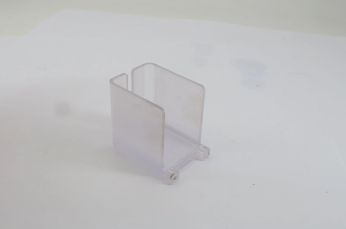
That finish distinction changes the process plan. The thin section and U-shaped geometry make clamp pressure and residual stress important. The polished exterior creates a secondary finishing requirement that can round edges or remove material if it is not controlled. The small threaded features require clean drilling/tapping without heat damage near the edge.
A sensible manufacturing route is:
- Confirm the exact PC stock and protective-film condition.
- Rough-machine with broad, low-stress support.
- Control heat and chip evacuation during thin-wall machining.
- Finish critical dimensions after the part has relaxed.
- Verify thread features and dimensional requirements from the drawing.
- Polish only the specified exterior zones.
- Visually inspect for haze, scratches, whitening, crazing, and edge damage.
- Package with surface protection so the cosmetic finish survives shipping.
The drawing uses its own tolerance scheme – X.X +/-0.20 mm, X.XX +/-0.10 mm, and X.XXX +/-0.025 mm unless otherwise specified. That is more defensible than claiming a generic “+/-0.01 mm on all polycarbonate parts.” The correct machining promise is always drawing- and geometry-specific.
Real CNC Machining Case 2: 3409M04 Clear Polycarbonate Side Guard
The 3409M04 Side Guard drawing specifies clear polycarbonate, a roughly 195 x 75 mm panel envelope, four 4.8 mm through holes, and the instruction to remove all sharp edges and corners. The supplied real-part image shows two long clear side-guard panels.
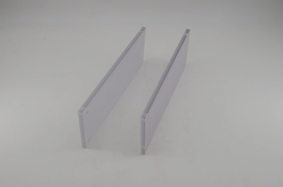
Although this geometry looks simple, sheet-like PC parts are often a workholding problem. A thin panel can deflect under point clamps, vibrate around a hole, or acquire scratches during handling. The process plan should therefore prioritize flat support, clean fixturing surfaces, chip removal under the panel, and controlled deburring.
For this type of component, quality is not only “did the CNC hit the hole coordinate?” It also includes:
- no edge breakout or drilling haze;
- no sharp burrs after deburring;
- no clamp dents or protective-film damage;
- flatness/shape acceptable after unclamping;
- hole size and position within the drawing tolerance system;
- no shipping scratches on visible transparent surfaces.
For machine guards, cover plates, inspection windows, and similar B2B parts, these cosmetic and handling controls can be as important to the customer as cycle time.
Quality Control for Machined Polycarbonate Parts
A robust inspection plan should follow the drawing and application rather than applying metal-part assumptions to every plastic feature.
| QC Stage | Control Point |
| Incoming material | Verify PC grade, color/clarity, stock thickness, lot/documentation where required, and protective film condition. |
| First article | Inspect critical dimensions after unclamping and thermal stabilization; an in-fixture reading can hide deflection. |
| In-process | Monitor hole size, wall thickness, thread condition, part movement, cutter buildup, and changing surface appearance. |
| Visual | Check scratches, haze, stress whitening, chips, cracks, polishing inconsistency, and contamination under controlled lighting. |
| Final dimensional | Use calipers, micrometers, height gauges, pin/thread gauges, optical measurement or CMM as appropriate; avoid excessive force. |
| Packaging | Protect polished/clear faces, prevent part-to-part rubbing, and preserve cleanliness through shipping. |
Polycarbonate vs Acrylic for Machined Clear Parts
The keyword “machining polycarbonate vs acrylic” usually reflects a material-selection decision. Acrylic (PMMA) is often chosen when optical appearance, surface gloss, and a crisp machined edge are the priority. It is also more brittle and more sensitive to chipping or crack initiation under impact.
Polycarbonate is typically the stronger choice for guards, covers, housings, and impact-resistant components. It tolerates mechanical impact better, but it demands more attention to heat, scratching, residual stress, and chemical compatibility during machining and finishing.
| Decision Factor | Polycarbonate (PC) | Acrylic (PMMA) |
| Impact/toughness | Higher; strong choice for guards and protective parts | Lower; more brittle under impact |
| Machining risk | Heat, smear, residual stress, scratches | Chipping/cracking from brittle behavior |
| Optical priority | Can be clear; machined faces may need controlled polishing | Often favored for high visual clarity and crisp finish |
| Typical B2B fit | Machine guards, housings, covers, impact-resistant windows | Display panels, optical/visual parts with modest impact demand |
For a purchasing engineer, the decision should be based on the functional failure mode: choose acrylic when optical clarity dominates and impact is modest; choose PC when toughness and impact resistance dominate, then design the machining and finishing process around heat/stress control.
What to Send for a Fast Polycarbonate Machining RFQ
A complete RFQ helps the machine shop quote the process rather than guess at it. Send:
- 3D CAD (STEP/STP preferred) plus the controlled 2D PDF drawing;
- exact material grade or approved equivalents, including clear/black, UV, FR, medical, optical, or glass-filled requirements;
- quantity, prototype/production status, and expected repeat volume;
- critical tolerances and GD&T;
- which surfaces are as-machined, polished, optically clear, textured, or coated;
- thread specifications and inspection requirements;
- cosmetic acceptance zones and scratch criteria;
- downstream chemicals, cleaners, adhesives, sterilization, UV exposure, or assembly loads that could affect PC;
- required material certificates, FAI/inspection report, or traceability;
- packaging requirements for protected transparent surfaces.
Rollyu Precision can review the drawing for thin-wall risk, internal radii, workholding, hole/thread strategy, surface finishing, and inspection before quotation. The objective is not simply to cut PC – it is to deliver a transparent engineering part that remains dimensionally stable, visually acceptable, and fit for assembly.
Frequently Asked Questions About Machining Polycarbonate
Is polycarbonate easy to CNC machine?
Yes. PC generally has good machinability, but it is heat- and stress-sensitive. Sharp tools, sufficient chip load, fast chip evacuation, stable low-pressure workholding, and compatible cooling are more important than using one fixed RPM.
What cutting speed should I use for polycarbonate?
There is no single defensible cutting speed for every PC part. Use the cutter manufacturer’s plastic-specific surface-speed/chip-load data, then calculate RPM from tool diameter and feed from flute count and chip load. Validate the process on the actual PC grade and geometry. For routing, Onsrud publishes a polycarbonate/soft-plastic chip-load range of about 0.004-0.012 in. for its routing approach.
What is the hardness of polycarbonate?
It depends on grade and test method. Representative unfilled-PC supplier data include Shore D 82 for Ensinger TECANAT natural and 111 N/mm² ball-indentation hardness for Covestro Makrolon 3106. Always use the exact material datasheet in engineering specifications.
Does polycarbonate need heat treatment after machining?
Not always. PC is not hardened by heat treatment. Stress-relief annealing may be useful for high material removal, thin/asymmetric geometry, narrow tolerances, chemical exposure, polishing, or evidence of residual stress. Use a grade-specific validated cycle rather than a generic temperature/time rule.
How do you stop polycarbonate from melting during CNC machining?
Prevent rubbing. Use a sharp tool with chip clearance, maintain an adequate feed/chip load, avoid unnecessary dwell, remove chips before they are recut, and use compressed air or a compatible cooling method when needed. If material begins building on the cutter, stop and correct the process rather than continuing the same cycle.
Can machined polycarbonate stay transparent?
Yes, but “transparent material” does not guarantee an optically clear machined surface. Tool marks, heat, scratches, and polishing method affect visual quality. Specify which faces need optical or cosmetic clarity and plan mechanical, diamond, or controlled solvent/vapor polishing accordingly.
Why can polycarbonate crack after drilling or cleaning?
Cracking can result from residual stress combined with heat, poor drilling conditions, edge stress, fastener load, or chemical exposure. A part may look acceptable immediately after machining and craze later after contact with an incompatible solvent or cleaner. This is why coolant and cleaning chemistry should be validated for the exact PC grade.
What tolerances are realistic for CNC-machined polycarbonate?
Tolerance capability depends on part size, wall thickness, stock condition, feature geometry, temperature, workholding, and inspection method. The safest approach is to quote and inspect against the actual drawing rather than publish one blanket tolerance. The two real cases in this article use different drawing-specific tolerance schemes.
| Send Your Polycarbonate Drawing for DFM + RFQ
Need a clear PC shield, machine guard, housing, panel, threaded component, or custom CNC polycarbonate part? Send Rollyu Precision your STEP/STP file and 2D drawing. We can review material grade, heat/stress risk, tool access, wall thickness, hole/thread details, polishing requirements, inspection points, and packaging before quotation. For the most accurate RFQ, include quantity, exact PC grade, critical tolerances, cosmetic/optical zones, surface finish, and any downstream chemical or assembly exposure. |
