

G10 machining looks straightforward until the cutting tool actually enters the material.
Unlike aluminum or conventional engineering plastics, G10 is a glass-fabric-reinforced epoxy laminate. Its combination of woven glass reinforcement and thermoset resin gives the material useful mechanical strength, electrical insulation, moisture resistance and dimensional stability, but the same glass reinforcement that makes G10 useful also makes it highly abrasive during machining.
For a buyer, design engineer or sourcing team, the important question is therefore not simply:
“Can G10 be CNC machined?”
Yes, it can.
The more useful questions are:
- How will tool wear be controlled?
- How will fiberglass dust be captured?
- How will the edges be protected from breakout or delamination?
- Should a feature be milled, drilled, thread-milled or fitted with an insert?
- How will laminate orientation affect the design?
- What tolerance is actually functional?
- How will dimensions be inspected as tools gradually wear?
- Is the specified material really G10, FR4 or another glass-epoxy laminate?
A stable G10 machining process must control all of these variables together.
Quick Answer: G10 can be milled, drilled, turned and profiled with CNC equipment. Production machining generally favors sharp carbide, diamond-coated or other abrasion-resistant cutting tools, rigid workholding and effective dust extraction. Exact speeds, feeds and coolant strategy should be validated for the actual material grade, tool, thickness, geometry and machine rather than copied from a universal cutting-data table.
What Is G10 Material?
G10 is a thermoset composite laminate made by combining woven glass fabric with an epoxy-resin system and consolidating the layers under heat and pressure.
This layered construction distinguishes G10 from ordinary homogeneous plastics.
Instead of cutting one uniform polymer, the tool repeatedly encounters:
glass reinforcement + epoxy matrix + laminate interfaces.
That explains many of the machining characteristics engineers see in production.
The material can provide a useful combination of high strength-to-weight ratio, electrical insulation and relatively low moisture absorption. Your supplied technical material also notes that certain mechanical characteristics vary with laminate orientation, meaning designers should not automatically treat G10 as isotropic.
Common CNC-machined G10 components may include:
electrical insulation components, mounting plates, structural brackets, spacers, fixtures, housings, sleeves, supports, instrument components and other non-conductive mechanical parts.
Actual suitability still depends on the specified grade, operating temperature, loading direction, environmental exposure and applicable customer standard.
Is G10 the Same as Garolite?
In commercial searches, Garolite G10, G10 Garolite and G10 machining are frequently used to describe similar glass-epoxy laminate products.
For engineering procurement, however, the purchasing specification should go deeper than a commercial material name.
A useful RFQ should identify, where applicable:
grade + governing specification + product form + thickness + certification requirements.
This is particularly important because the broader Garolite/industrial-laminate category can include materials with different resin and reinforcement systems.
G10 vs FR4 — Are They the Same Material?
They are closely related, but they should not automatically be treated as interchangeable.
Both are commonly glass-fabric/epoxy laminates. FR4 is specifically associated with flame-retardant glass-epoxy laminate formulations, while G10 is classified separately as an epoxy-glass laminate. Norplex-Micarta, for example, distinguishes NEMA G-10 epoxy-glass materials from NEMA FR-4 flame-retardant epoxy-glass products.
For a precision CNC part, do not substitute one for the other solely because the parts appear similar or share the familiar green laminate appearance.
Specify the actual material required by the design.
Why Is G10 Difficult to Machine?
The challenge is not whether a CNC machine can move through the programmed toolpath.
The challenge is maintaining tool condition, surface quality, dimensional consistency and a controlled machining environment throughout the production run.
Glass Fibers Accelerate Cutting-Tool Wear
Glass reinforcement is abrasive.
As the cutting edge gradually loses sharpness, several problems can appear together:
rougher edges, increasing cutting forces, heat generation, dimensional drift, fiber pull-out and additional deburring requirements.
The supplied technical reference therefore recommends carbide or more wear-resistant tooling rather than treating G10 like a conventional soft plastic.
For production work, tool life should be treated as a process variable.
A machine can continue running long after the tool has reached the point where edge quality is no longer acceptable.
G10 Produces Dust Rather Than Conventional Metal Chips
Machining G10 produces fine particulate and short fiber-containing debris rather than the predictable curled chips familiar from metal machining.
This affects both process stability and shop control.
Dust can contaminate the work area, accumulate around the workholding and enter machine components if it is not managed correctly.
The source material specifically recommends dedicated extraction for shops that regularly machine G10 and other fiber-reinforced composites.
From an occupational-safety standpoint, dust control should be treated as an engineering-control issue rather than simply a cleaning task. OSHA describes enclosures and local exhaust ventilation as primary engineering controls used in advanced-composite operations, and local exhaust is intended to capture contaminants close to the source.
Specific PPE, filtration and exposure-control requirements should follow the material SDS, workplace risk assessment and applicable local regulations.
Delamination and Edge Breakout Must Be Controlled
G10 is laminated.
Poor tool condition, excessive local cutting force, inadequate backing support or aggressive drilling can damage the edge or separate material near laminate interfaces.
Drilled holes, countersinks, thin tabs and features positioned near an external edge therefore deserve particular attention.
The machining strategy should prioritize a sharp cutting action and adequate support rather than simply increasing spindle speed.
Part Orientation Can Matter
Because G10 is constructed in layers, mechanical response can vary with material orientation.
That becomes important for thin walls, flexural features, heavily loaded threaded connections and parts cut deeply through sheet thickness.
A drawing that treats the material like homogeneous aluminum may therefore miss design factors that affect the final component.
Best CNC Machining Processes for G10 and Garolite
G10 can support a wide range of subtractive manufacturing operations.
The process should be selected according to geometry rather than forcing every feature into one machining method.
CNC Milling
CNC milling is commonly used for:
plates, pockets, curved profiles, slots, mounting patterns, counterbores, insulating brackets, fixture plates and complex three-dimensional surfaces.
Secure workholding is essential.
Thin sheet or poorly supported areas can vibrate, causing rough edges or local laminate damage even when nominal machine positioning accuracy is excellent.
When possible, the machining plan should provide support close to the cutting zone.
CNC Turning
Rod, tube or preformed laminate stock may be turned when the component contains rotational geometry such as:
bushings, sleeves, cylindrical insulators, spacer bodies and flange-style components.
Sharp tooling and controlled engagement become particularly important because increasing tool wear can affect both diameter and surface condition.
Drilling and Counterboring
Hole quality is often one of the most sensitive aspects of G10 machining.
A drilling strategy should account for:
tool sharpness, backing support, hole diameter, hole-to-edge distance, breakout at the exit surface and required countersink or counterbore geometry.
For a precision mounting hole, dimensional acceptance should include both nominal diameter and the condition of the laminate around the hole.
Thread Milling, Tapping and Threaded Inserts
Threads deserve careful DFM review.
Your source material specifically notes that thread milling may be preferable for some internal features because excessive pressure or heat can increase delamination risk. It also recommends considering threaded inserts where a joint will experience significant torque or repeated assembly cycles.
That distinction matters.
A thread that survives first assembly is not necessarily the same as a thread designed for repeated servicing.
Where repeat torque, pull-out strength or repairability is critical, the engineering team should evaluate an insert rather than automatically machining the thread directly into the laminate.
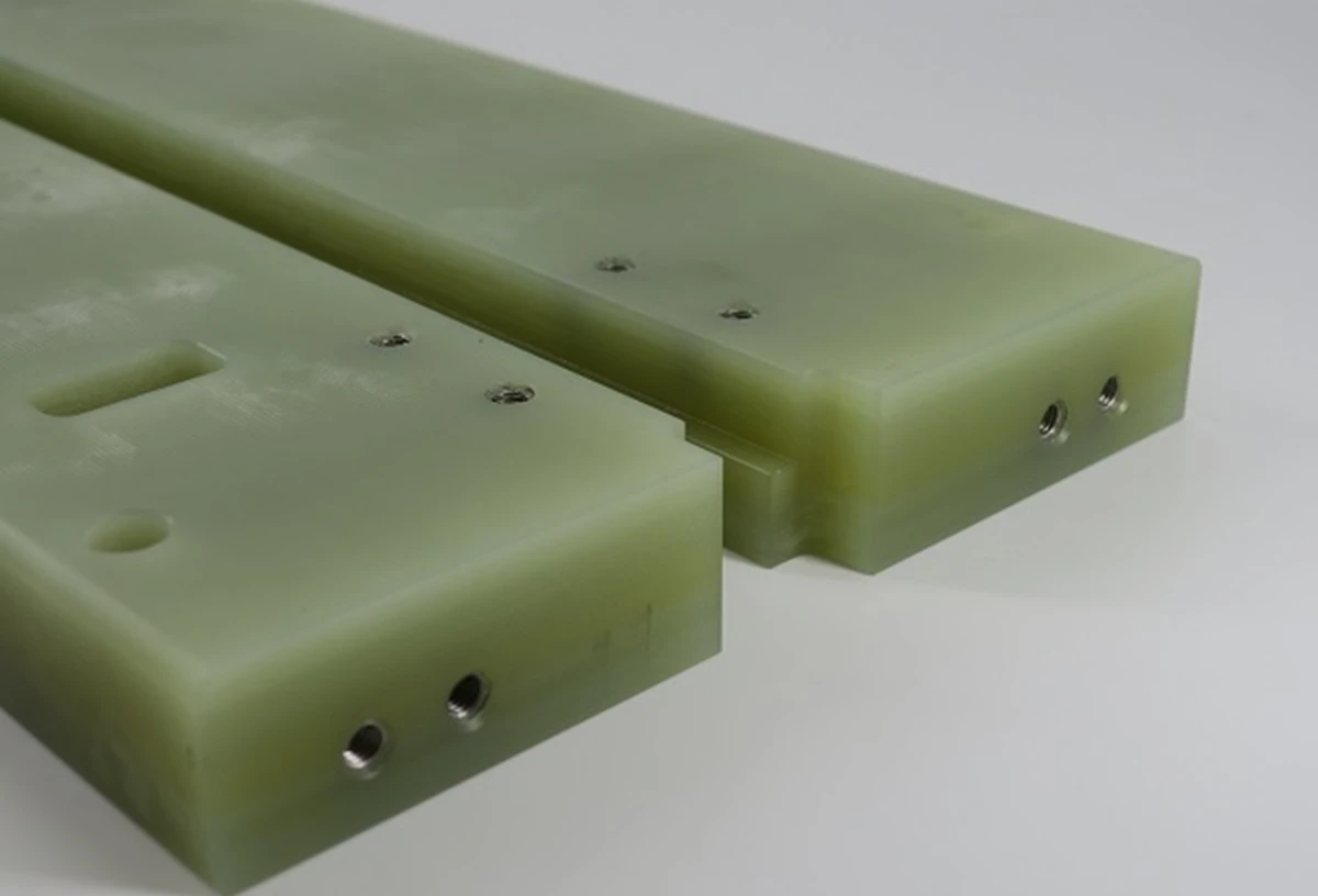
Threaded inserts improve thread strength and durability in G10 and FR4 parts, making them suitable for repeated assembly, higher fastening loads, and precision mechanical applications.
What Cutting Tools Are Best for G10 Machining?
There is no single cutter that is best for every G10 component.
Tool selection should reflect:
production quantity, material thickness, feature size, acceptable edge condition, machine rigidity and expected tool life.
For many jobs, sharp solid-carbide tooling is a practical baseline.
For longer production runs or particularly abrasive work, diamond-coated or other composite-specific tools may offer better wear resistance.
The source material similarly identifies carbide and diamond-coated tooling as useful options because the glass reinforcement rapidly degrades conventional cutting edges.
Why We Do Not Publish One “Best Cutting Speed”
A common Google search is:
“What speed should I use to machine G10?”
The technically responsible answer is that cutting data must be contextual.
The correct parameters depend on:
tool diameter, flute geometry, coating, radial engagement, axial depth, material thickness, laminate grade, workholding stiffness, dry or wet process strategy, machine spindle and desired edge quality.
Publishing one RPM or feed rate without these variables can create more risk than value.
A professional machining supplier should establish a starting window, perform controlled trial cuts and then monitor:
edge quality, temperature, dust behavior, tool wear and dimensional stability.
That is more useful than copying an isolated number from a generic internet chart.
Should G10 Be Machined Dry or With Coolant?
There is no universal answer.
Dry machining can simplify post-process cleaning and avoid introducing liquid into the part or machine process, but it places greater emphasis on effective dust extraction.
A controlled wet process may help suppress airborne particulate and manage cutting heat, but coolant compatibility, contamination requirements and post-machining cleaning must be evaluated for the actual application.
Do not automatically state that “medical G10 must be dry machined” or that “G10 should always be flood cooled.”
The correct decision belongs in the process specification.
DFM Guidelines for G10 Precision Parts
Good G10 machining starts at the drawing.
Use Realistic Internal Corner Radii
Very small internal radii require small-diameter tools.
Small tools have less rigidity and can wear rapidly when cutting glass-filled laminate.
If the assembly does not functionally require a sharp internal corner, increasing the radius may reduce cost and improve process stability.
Consider Standard Sheet Thicknesses
G10 is commonly sourced as sheet, rod or other laminate stock forms.
Selecting a stock thickness close to the finished geometry can reduce unnecessary material removal and help preserve laminate structure.
Support Thin Features
Thin arms, long slots, narrow bridges and unsupported tabs can become sensitive to vibration and breakout.
Where possible, add temporary machining support, modify the operation sequence or reconsider the local geometry.
Do Not Apply Ultra-Tight Tolerances Everywhere
A tolerance should be tied to function.
For example, a locating bore, bearing interface or alignment feature may genuinely require close dimensional control.
A non-functional exterior edge may not.
A blanket tight tolerance across an entire G10 drawing can increase tool changes, inspection time, setup complexity and scrap risk without improving the assembly.
Instead, define:
critical fits, critical datums, hole positions and interface surfaces separately from general dimensions.
Real G10 Machining Examples From Rollyu Precision
The following production photographs show representative G10/green glass-epoxy machined components.
Important case-study note: the photographs demonstrate machining geometry and manufacturing methods only. Customer identity, final product, industry and functional application are not disclosed and should not be inferred from appearance alone.
Case Example 1 — Small G10 Brackets With Bosses and Cross Holes
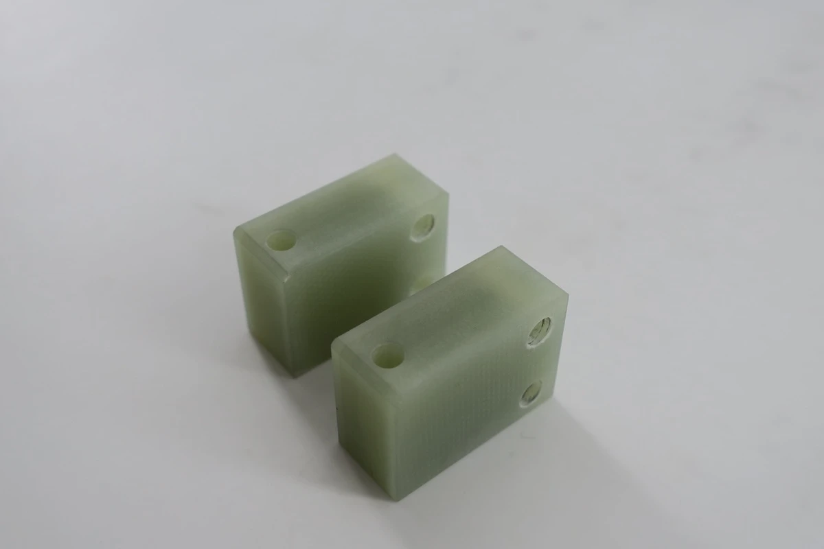
The first photograph shows two small green laminate components with raised cylindrical bosses and multiple drilled holes.
Although the parts appear simple, this geometry requires control of several machining factors:
- boss-to-base perpendicularity,
- drilled-hole position,
- laminate edge condition,
- support during milling,
- breakout around the smaller holes.
For low-volume precision components, a seemingly simple bracket can still require careful fixture design because the small footprint limits available clamping area.
Case Example 2 — Large Profiled G10 Plates and Slotted Structural Component
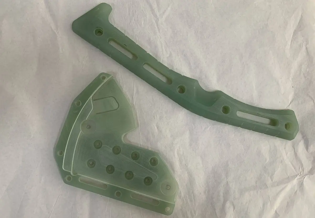
Larger flat G10 components with curved profiles, multiple holes, pockets and long slots.
These features illustrate why G10 sheet machining is often more than basic 2D routing.
Long slots can reduce local stiffness. Closely spaced holes can affect remaining laminate strength. Large perimeter profiles require stable edge quality around a significant cutting distance.
Tool-condition monitoring becomes increasingly important because an abrasive material may gradually change surface and edge quality during the same batch.
For custom G10 components used in tactical equipment, field electronics, protective systems, and ruggedized assemblies, Rollyu Precision evaluates feature spacing, laminate thickness, workholding, tool wear, edge condition, and inspection requirements before production to improve dimensional consistency and reduce the risk of delamination or assembly problems.
Case Example 3 — Annular G10 Housings With Metal Threaded Inserts
The annular components combine machined glass-epoxy laminate geometry with installed metallic threaded inserts for laser optic systems.
This is an important DFM example.
Where fasteners are removed and installed repeatedly, an engineered metal insert may provide a more robust assembly interface than relying solely on a directly machined laminate thread.
The correct insert type, installation method, wall thickness and pull-out requirement must still be defined by the assembly design.
Case Example 4 — Cylindrical and Flanged G10 Components
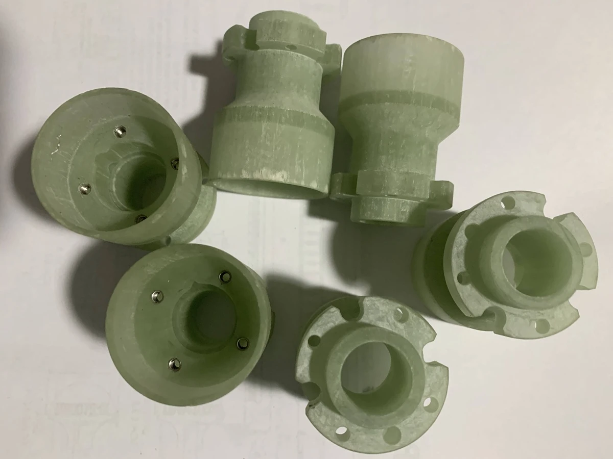
Demonstrates that G10 machining is not limited to flat sheet profiles.
The components include cylindrical forms, flanges, bores, radial features and mounting holes for leak test systems.
Manufacturing this style of part may require a combination of turning, milling and drilling.
When multiple setups are required, datum strategy becomes important because accumulated setup error can affect bore location and flange relationships.
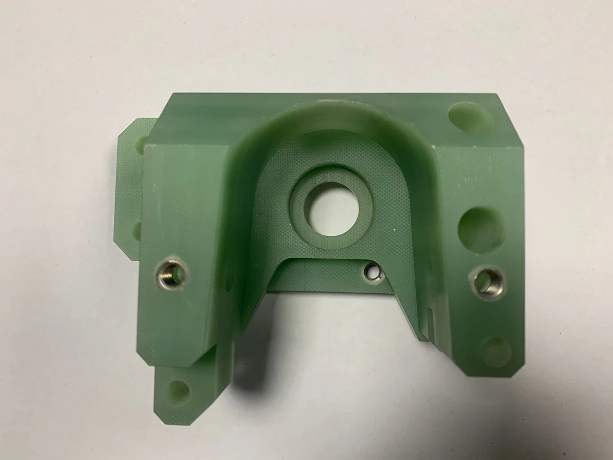
Case Example 5 — Pocketed G10 Mounting Bracket With Inserts
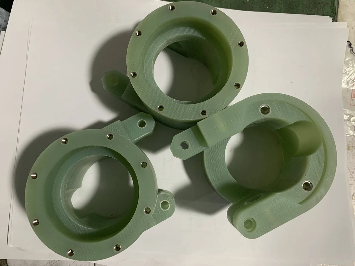
This component includes a deep U-shaped pocket, a central bore, drilled mounting features and metallic threaded inserts.
The geometry illustrates several practical sourcing questions:
How will the inside walls be supported during machining?
What internal corner radius is acceptable?
Which holes are locating features?
Which inserts are functional threads?
Which dimensions require inspection after insert installation?
These are precisely the questions that should be resolved during DFM review rather than after the first batch is complete.
Surface Finish and Edge Quality on Machined G10
Machined G10 does not behave like polished stainless steel or acrylic.
The cut surface normally retains a matte composite appearance, and exposed laminate layers may remain visually apparent depending on cutting direction and feature orientation. Your supplied material also notes that countersinks or surfaces cut across the laminate can appear different because different layer cross-sections become visible.
That appearance is not automatically a quality defect.
The drawing should distinguish between:
cosmetic appearance and functional edge requirements.
If an edge must be burr-free, sealed, coated, radiused or otherwise treated, specify the requirement.
Do not rely on the word “smooth” alone.
Quality Control for CNC-Machined G10 Parts
Inspection should detect process drift, not simply reject finished parts.
This is particularly important with abrasive composites because tool wear can change gradually.
A production inspection plan may include:
first-article verification, in-process dimensional checks, hole-size inspection, profile verification, visual edge inspection, thread/insert verification and final dimensional inspection.
The appropriate equipment depends on feature geometry and tolerance and may include calibrated hand instruments, gauges, optical inspection or coordinate measurement equipment where suitable.
For repeated production, one particularly useful question is:
Does the last part in the batch still have the same edge and dimensional quality as the first part?
That question connects machining process control directly to buyer risk.
What Should You Send for a G10 Machining Quote?
A supplier can quote more accurately when the RFQ defines the finished requirement rather than simply saying “G10 part.”
Provide:
- 3D CAD file such as STEP/STP.
- 2D engineering drawing.
- Exact material designation — G10, FR4 or another specified laminate.
- Governing material standard when required.
- Material thickness or preferred stock form.
- Critical dimensions and GD&T.
- General tolerances.
- Hole and thread requirements.
- Threaded-insert specification where applicable.
- Edge-break, radius and deburring requirements.
- Surface or coating requirements.
- Material certification requirements.
- Inspection or FAI requirements.
- Prototype and production quantity.
- Operating environment where it affects material selection.
This lets the manufacturing engineer evaluate the complete process instead of estimating only cutting time.
How to Evaluate a G10 Machining Supplier
Do not evaluate a supplier only by asking:
“Can you machine G10?”
A more useful supplier assessment asks how the shop manages:
tool wear, dust extraction, workholding, thin features, hole breakout, threaded interfaces, inspection frequency and batch-to-batch repeatability.
For abrasive composite machining, process discipline matters as much as machine specification.
A supplier may be able to produce one acceptable sample while still lacking a stable production route.
For repeat orders, ask how the supplier identifies dimensional or edge-quality drift before the entire batch is complete.
Why Source Custom G10 Machined Parts From Rollyu Precision?
Rollyu Precision supports custom machining of engineered plastics and composite materials alongside precision metal machining.
For a G10 or FR4 project, the manufacturing review can cover:
material specification → DFM → stock planning → CNC milling/turning/drilling → threaded inserts → dimensional inspection → cleaning → packaging.
The goal is not simply to make the geometry visible in the CAD model.
The objective is to deliver a finished component with controlled dimensions, acceptable laminate edges and a manufacturing route that can be repeated from prototype through production.
For designs containing complex pockets, multiple datums, thin sections, close-position holes or installed hardware, reviewing the process before quotation can reduce unnecessary manufacturing risk.
Frequently Asked Questions About G10 and Garolite Machining
Can G10 be CNC machined?
Yes. G10 can be CNC milled, drilled, turned and profiled. Because the glass reinforcement is abrasive, tooling, dust control, workholding and edge quality require more attention than when machining many conventional plastics.
Is G10 the same as Garolite?
G10 is an engineering grade of glass-epoxy laminate. “Garolite” is commonly encountered as a commercial laminate term in the market, but engineering drawings should specify the actual required grade instead of relying only on a commercial name.
What is the difference between G10 and FR4?
Both are glass-fabric/epoxy laminates, but FR4 is associated with flame-retardant formulations. They should not automatically be substituted for each other. Material selection should follow the drawing, standard and application requirements.
What tools are best for G10 machining?
Sharp carbide tools are commonly used. Diamond-coated or other abrasion-resistant composite tooling may be advantageous for longer production runs. Tool choice should be validated against the actual feature, grade and production quantity.
Why do tools wear quickly when machining G10?
The woven glass reinforcement is abrasive. As the cutting edge wears, cutting forces and heat can increase while edge quality and dimensions may gradually deteriorate.
How can delamination be reduced?
Use sharp tooling, rigid support, appropriate cutting engagement, controlled drilling strategies and sufficient material support around sensitive edges. Tool wear should also be monitored because a dull tool can increase local cutting forces.
Can threads be machined directly into G10?
They can be produced in suitable designs, but the best method depends on thread size, laminate thickness and loading. Thread milling or installed metal inserts may be preferable for certain parts, particularly where repeated assembly or higher fastening loads are expected.
Should G10 be machined dry?
Dry machining is possible but requires effective dust management. Wet machining may suppress particulate and manage heat in some processes. The choice should consider material compatibility, cleanliness requirements, machine configuration and the customer specification.
What tolerance can G10 machining achieve?
There is no responsible universal tolerance for every G10 component. Achievable tolerance depends on geometry, thickness, laminate orientation, tool access, workholding, feature size, inspection method and production volume. Tight tolerances should therefore be assigned to functional features rather than assumed for the entire part.
Is G10 suitable for aerospace or medical equipment?
G10-type laminates may be used in demanding equipment, but application suitability cannot be determined from the material name alone. The designer must define the required grade, specification, environmental conditions, mechanical requirements and any applicable industry or regulatory requirements.
What files should I send for a G10 machining quotation?
Send a STEP model and 2D drawing together with the material grade, quantity, tolerances, GD&T, thread/insert details, inspection requirements and any material certification or surface requirements.
Request a Quote for Custom G10 or Garolite Machined Parts
Are you sourcing G10 machining, Garolite machining or custom FR4 machined components for a prototype or repeat-production project?
Send Rollyu Precision your:
STEP file + 2D drawing + material specification + quantity + tolerance + insert/thread requirements + inspection requirements.
Our engineering team can review potential manufacturing risks involving:
abrasive tool wear, thin laminate features, small holes, edge breakout, delamination, complex pockets, installed inserts, close-position features and inspection strategy.
Request a DFM Review and Quote
From prototype validation to repeat production, the objective is simple:
machine the G10 component to the drawing while controlling the entire process—not merely cutting the shape.
