

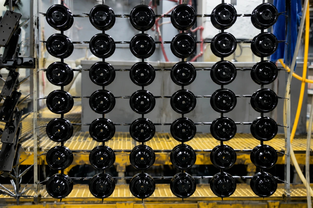
A CNC aluminum part can pass machining inspection and still become unacceptable after finishing. A hard-anodized bore can return undersize; threads can bind because coating reached an unmasked area; black anodized lots can differ visually; clear finishes can reveal alloy or machining variation; and powder coating can build around holes or mating interfaces.
These problems are often described as “anodizing issues” or “coating problems,” but the failure may originate before, during or after the finishing operation. For precision parts, the final condition is created by a chain: material selection, CNC machining, deburring, mechanical or chemical pretreatment, masking, surface treatment, sealing or post-treatment, inspection, handling and packaging.
Why Aluminum Surface Treatment Problems Keep Repeating
Aluminum finishing is influenced by alloy/temper, material lot, machined surface condition, deburring, blasting or brushing, cleaning, coating chemistry, thickness, dye/seal, masking, weld or heat-affected areas, and post-finish handling. That is why a repeated defect should be traced through the whole route instead of being assigned automatically to the coating bath.
Two components described only as “black anodized aluminum” can look different because the substrate and pretreatment are different. Bead blasting, as-machined tool paths, Timesaver/brushing and polishing create different textures that remain relevant after anodizing.
For appearance- or fit-critical parts, “BLACK ANODIZE” is rarely a complete engineering definition. The controlled requirement may also need specification/type/class, functional thickness or acceptance requirement, color, seal, pretreatment, masking, critical post-finish dimensions and cosmetic acceptance.
Start With the Failure Mode, Not the Finish Name
| Observed Problem | What May Need Investigation | Evidence of Better Control |
| Lot-to-lot color variation | Alloy/temper or material-lot variation; machining/blasting condition; dye, film condition or sealing; viewing/acceptance method | Separate cosmetic acceptance from functional acceptance; retain lot identity; use an approved sample or defined measurement method where appearance is critical. |
| Bore, shaft or slot out of tolerance after finishing | Coating contribution not considered in the machining plan; wrong masked/unmasked condition; inspection referenced to the wrong process stage | Identify dimensions that matter after treatment; review machining allowance and masking before release; verify critical dimensions after finish where required. |
| Threads difficult to assemble | Thread surfaces coated unexpectedly; allowance or masking not defined; debris or handling damage | Define the thread finish condition on the drawing/route; protect and inspect critical threads after finishing. |
| White spots, burning, powdering or uneven anodic appearance | May relate to substrate condition, pretreatment, alloy response or anodizing process parameters | Contain the lot and investigate the mechanism; do not treat cosmetic rework alone as root-cause closure. |
| Scratches on finished parts | Part-to-part contact, dirty handling, fixtures, transport or packaging | Separate finishing defects from post-finish handling damage; use clean protection after inspection. |
| Powder coat interferes with assembly | Dry-film buildup at holes, edges, threads or mating surfaces; masking not aligned with assembly | Review masking and interface dimensions before coating; inspect the features that control assembly. |
| Grounding/contact area becomes insulated | Wrong surface treatment or missing masking | Define conductive/contact areas explicitly; select Chem Film or masked treatment only when the drawing/application requires it. |
| Plating adhesion or blistering concern | Pretreatment, substrate condition or plating-process issue | Review the aluminum pretreatment and processor controls; distinguish deposited-coating adhesion issues from anodizing, which is a conversion process. |
Risk-control note: a visible defect is not automatically proof that the chemical process was the sole cause. The investigation should separate material, machining, pretreatment, coating, handling and packaging contributors before corrective action is closed.
Aluminum Surface Treatment Selection Guide for Precision CNC Parts
There is no universally “best” aluminum finish. The appropriate process depends on the function that must remain after treatment. The ranges below are planning references from the supplied Rollyu selection material, not universal specification limits. The drawing, PO, current standard revision, processor capability and validated project requirement take precedence.
| Treatment | Planning Reference* | Useful When | Main Precision-Part Risk |
| Type II Anodizing | Representative ~5–25 μm | Corrosion protection, color, moderate wear, cosmetic or general precision parts | Color/texture variation, sealing, masking and dimensional effect |
| Type III Hard Anodizing | Representative ~25–75 μm | Higher wear demand, sliding/mechanical interfaces, electrical insulation where specified | Greater dimensional influence; fits, bores, threads and mating surfaces need early review |
| Chemical Conversion / Chem Film | Very thin conversion layer; dimensional influence usually small | Corrosion protection, paint adhesion, grounding/electrical contact where specified | Correct type/class, approved chemistry, contact areas and customer specification |
| Electroless Nickel | Representative ~5–50 μm | Uniform deposited metallic coverage, corrosion/wear, complex geometry | Adds material to exposed surfaces; pretreatment, masking, fit and adhesion control |
| Powder Coating | Representative ~60–120 μm | Durable color, corrosion protection, housings, guards, frames | Dry-film buildup, edge coverage, holes, threads, assembly interfaces and cure |
| Wet Paint / Liquid Coating | Representative ~20–100 μm | Flexible color/gloss and application-specific environmental protection | Overspray, masking, dry-film thickness, cure, adhesion and cosmetic acceptance |
*Representative planning ranges only. Do not copy them into a drawing without checking the applicable specification, alloy, finish system and processor capability.
Type II Anodizing: Good General-Purpose Protection, but Appearance Still Needs Control
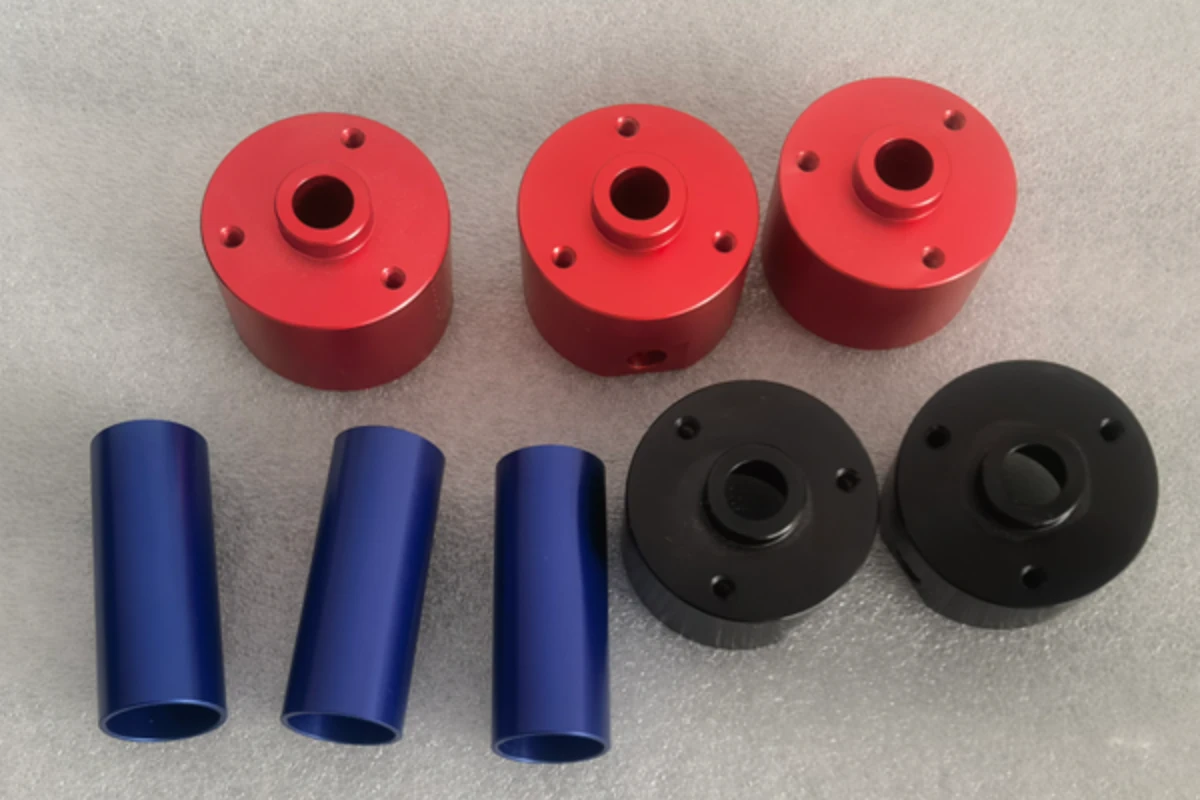
Type II sulfuric acid anodizing is common on CNC aluminum housings, mounts and instrumentation because it can combine corrosion protection, moderate wear performance and color. Clear or dyed appearance still depends on the substrate, pretreatment and sealing route.
When appearance matters, an approved sample or defined measurement method is stronger than a verbal color description. If a numerical color tolerance such as ΔE is required, the contract should define the instrument, illuminant and method rather than treating one threshold as universal.
For dyed anodizing, sealing is part of the final system. Nickel acetate is one recognized sealing route, but the required seal should follow the drawing/specification or validated project process.
Type III Hard Anodizing: Dimensional Planning Matters as Much as Wear Performance
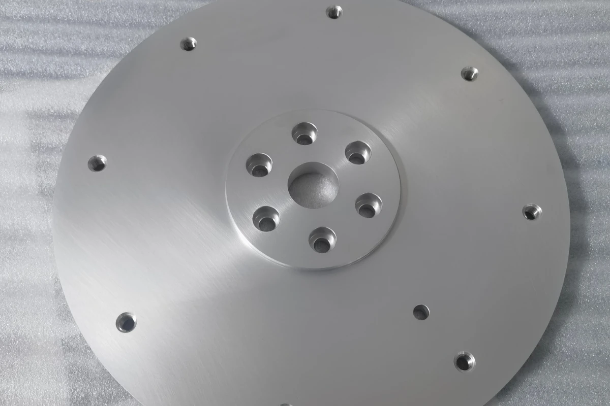
Hard anodizing is commonly considered for components needing more demanding wear performance than a typical decorative Type II finish, including certain sliding parts, fixtures and robotic mechanisms.
The main risk is treating hard anodizing as a note added after finish machining. Anodizing consumes some aluminum while producing oxide growth, and the outward dimensional contribution varies by alloy and process; a universal growth percentage is unsafe.
Critical bores, fits, shafts, slots, threads, sealing surfaces and mating faces should be reviewed while machining can still be adjusted. Define which dimensions apply before finish, which apply after finish, which areas are masked and what post-finish inspection confirms function.
Chem Film / Chemical Conversion: Thin Functional Protection for Conductive or Paint-Bonding Areas
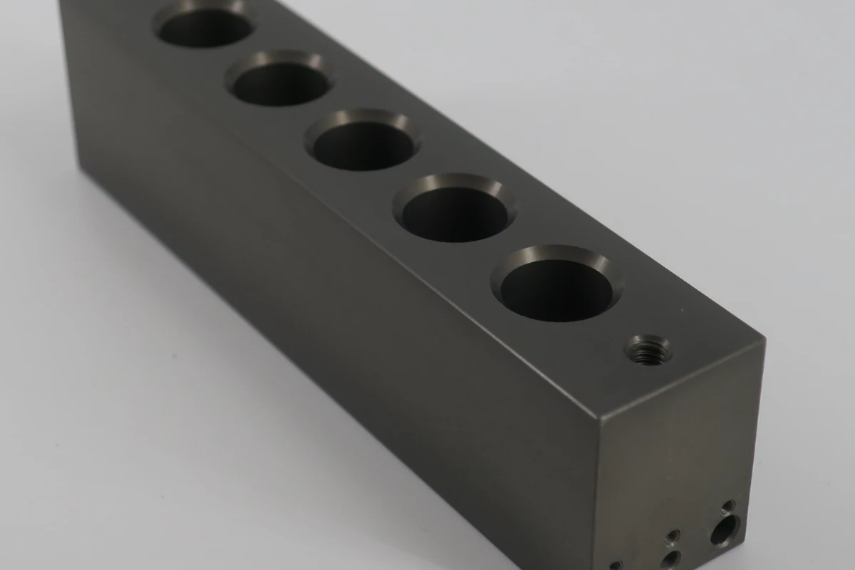
Chemical conversion coatings are much thinner than anodic coatings and are often chosen when corrosion protection, paint adhesion or electrical contact/grounding is needed with small dimensional influence.
MIL-DTL-5541 is a current U.S. military detail specification for chemical conversion coatings on aluminum and aluminum alloys. Under it, Type II uses compositions without hexavalent chromium and Class 3 addresses applications requiring low electrical resistance. If invoked, the drawing/PO controls the exact requirement.
A supplier should not claim MIL-DTL-5541 compliance merely because a processor offers Chem Film. Qualification, required chemistry/class, tests and documentation remain order-specific.
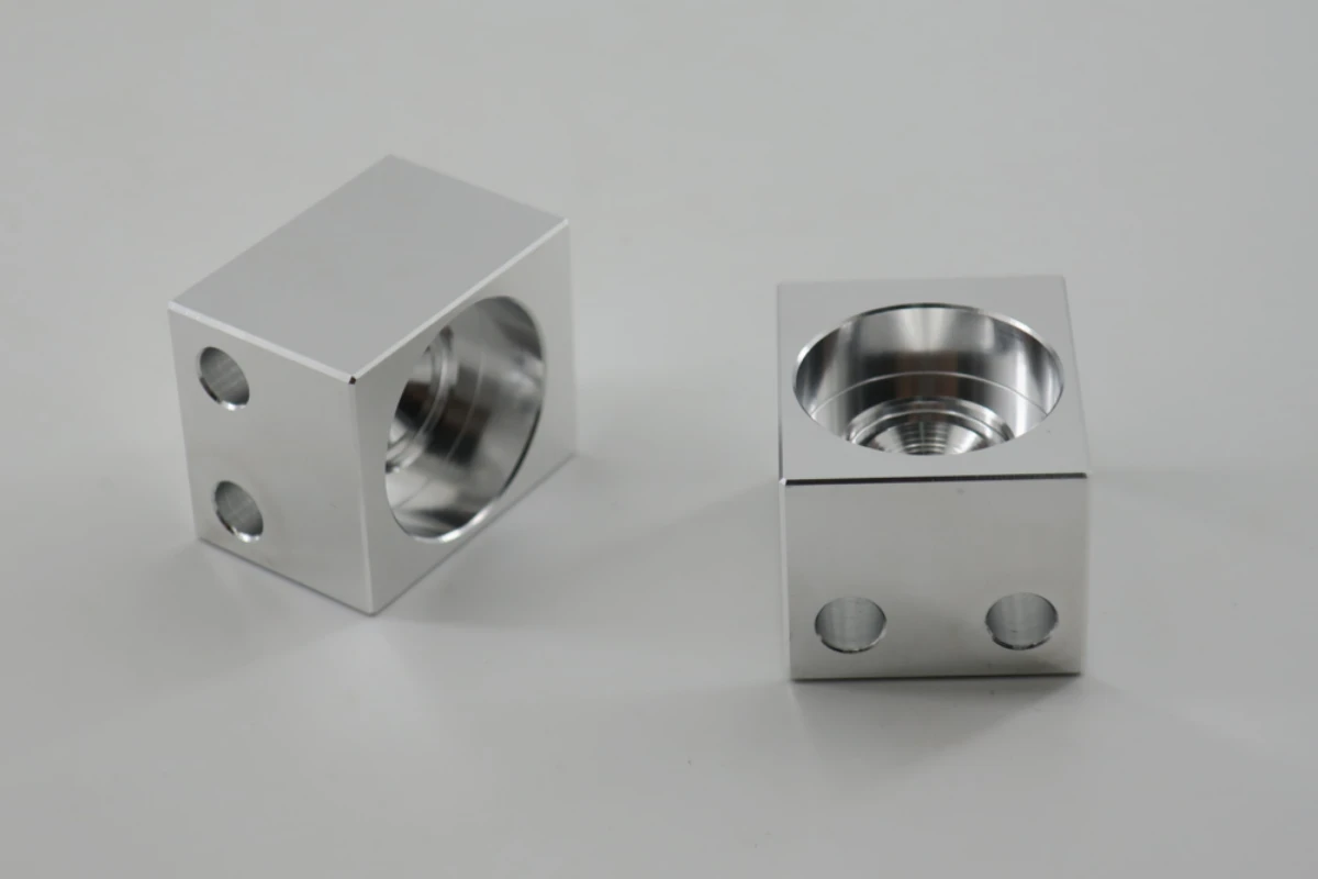
Electroless Nickel: Uniform Deposited Coverage Requires Pretreatment and Fit Control
Electroless nickel can be useful where a deposited metallic layer is required for corrosion resistance, hardness, wear or relatively uniform coverage on complex geometry. Because it adds material to exposed surfaces, the machining allowance and masking strategy are different from a thin chemical conversion coating.
On aluminum, pretreatment is especially important; plating systems typically require a process designed to create a suitable active surface before nickel deposition. Adhesion, thickness and post-plate dimensions therefore need to be controlled as a system.
If a precision bore, thread, locating diameter or sealing interface is plated, the drawing should make that condition explicit. If it is not meant to be plated, masking or a defined post-process step should be part of the route.
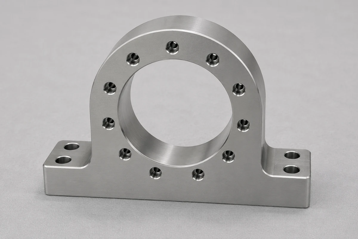
Powder Coating, E-Coating and Wet Paint: Functional Coatings Still Need DFM
Organic coatings can provide durable color and environmental protection for housings, frames and guards, but their film build can interfere with holes, threads, edges, contact points and mating faces when masking is not planned.
Powder coating quality also depends on pretreatment, dry-film thickness, adhesion, cure, edge coverage, masking and handling. E-coating and wet paint have different process controls and should not be reduced to a generic “painted aluminum” requirement.
A cosmetic coating should not be expected to hide deep tool marks, dents or inconsistent blasting; substrate preparation remains part of the visible finish.
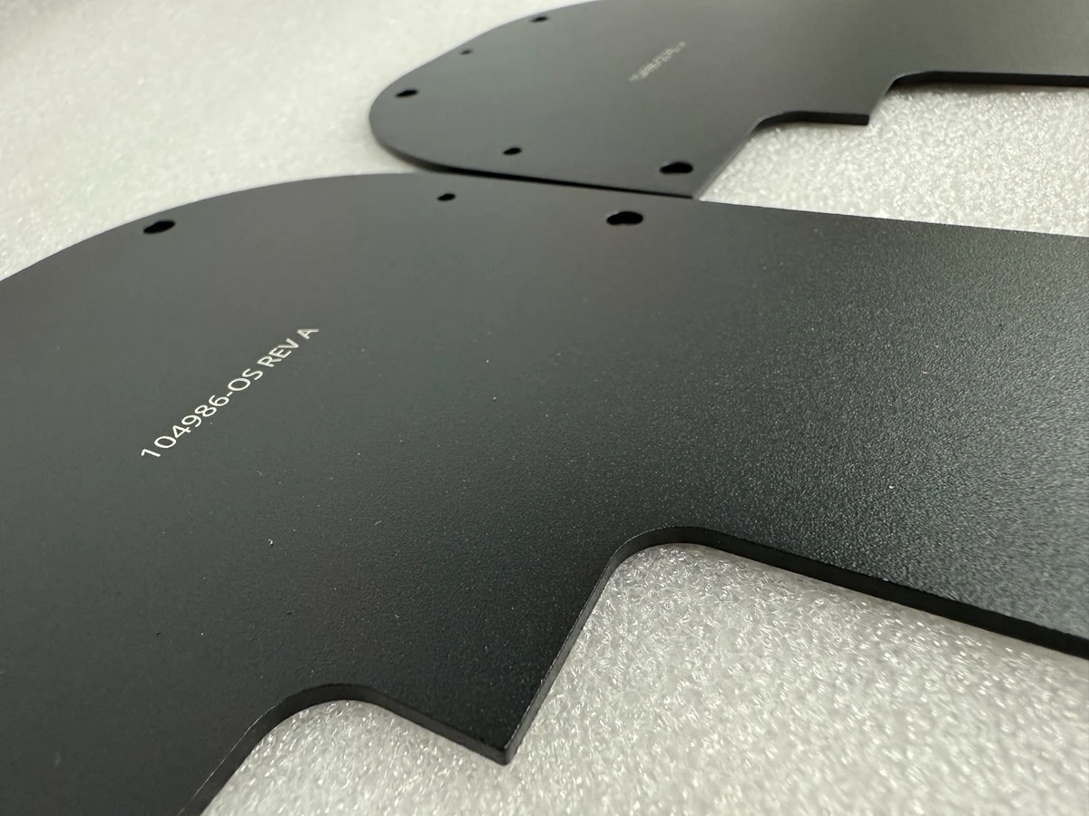
Bead Blasting, Sandblasting, Brushing and Polishing Are Part of the Finish Route
Mechanical pretreatment often determines the final visual character of an anodized or painted component. Bead blasting can create a fine matte surface, sandblasting can produce a stronger texture, brushing or Timesaver finishing creates a directional grain, and polishing increases reflectivity. These are not interchangeable cosmetic extras; they change the substrate that the coating receives.
For repeat production, the pretreatment needs the same level of definition as the coating when appearance matters. “Bead Blast + Black Anodize” is a different finish route from “As-Machined + Black Anodize,” even though both parts may ultimately be black.
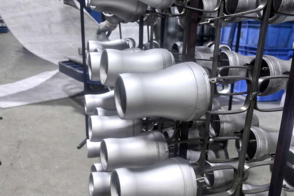
Laser Marking for CNC Machined Medical Parts
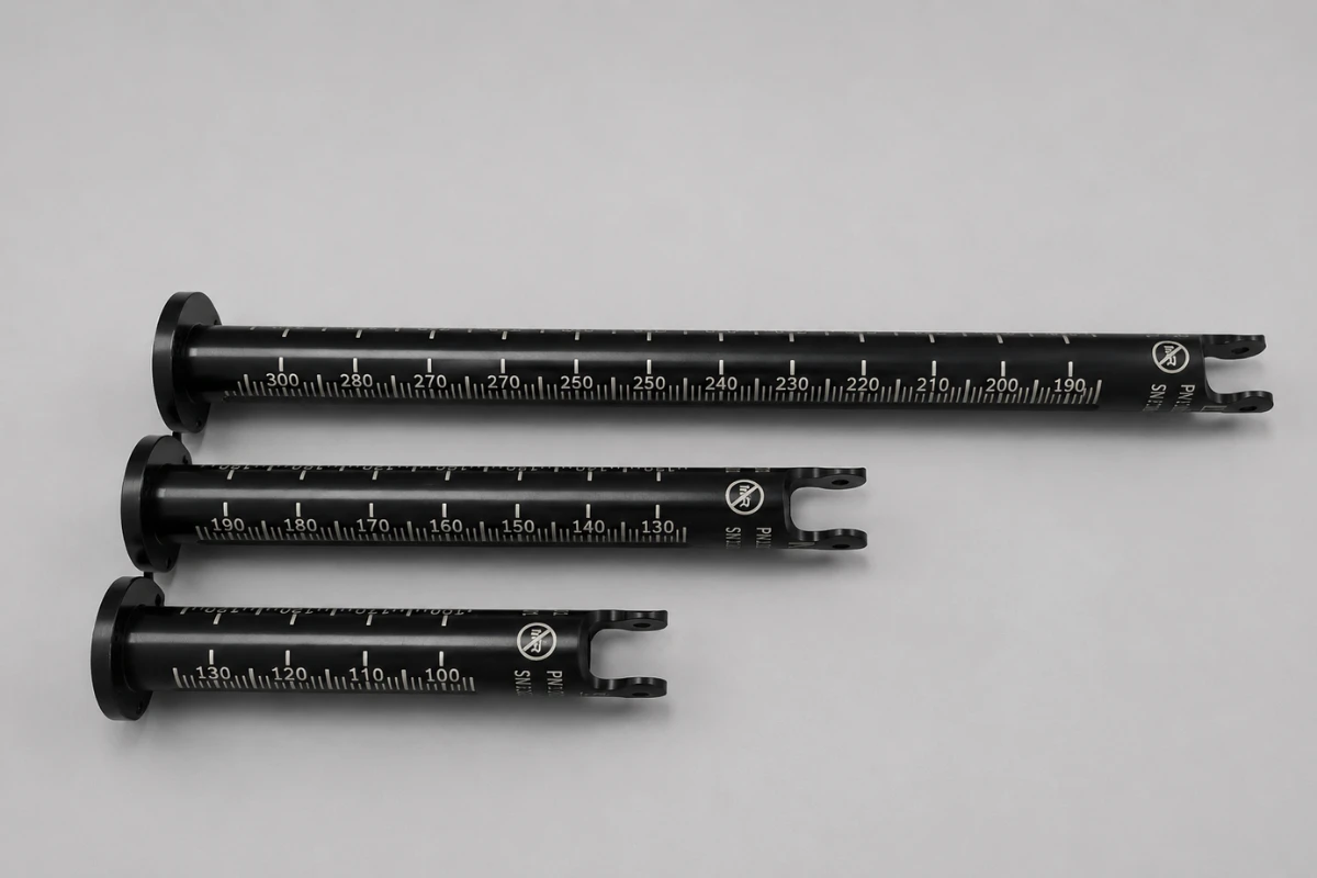
Laser marking is commonly used on CNC machined medical parts for permanent identification and traceability, including part numbers, serial numbers, lot codes, Data Matrix codes, or UDI-related information where specified. The marking location, depth, contrast, and heat-affected area should be controlled so identification remains legible without affecting critical dimensions, sealing surfaces, fatigue-sensitive areas, or functional interfaces.
Dimensional Compensation and Masking Are Where Machining and Finishing Meet
For mechanical engineers, the most expensive aluminum finish problems are often not color problems. They are assembly problems created when the surface treatment and tolerance stack were planned separately.
Threads, bearing/locating fits, precision bores, O-ring and sealing surfaces, grounding points, bonding areas and datums should be reviewed before release. Hard anodizing generally demands more dimensional planning than thin conversion coating, while nickel, powder and paint add material to exposed surfaces.
The drawing should state which critical dimensions apply in the finished condition. Where coating changes a functional interface, the inspection plan should verify that finished feature when required.
What Evidence Actually Builds Confidence in a Surface-Finish Process?
Clear drawing interpretation: The finish is identified by the applicable specification or controlled process requirement, not only by a color name. Ambiguous or conflicting notes are resolved before production.
Masking definition: Threads, precision bores, bearing fits, grounding points, sealing surfaces and other functional interfaces are identified on the drawing, marked-up view or controlled work instruction.
Pre- and post-finish inspection logic: Inspection follows the dimension that matters functionally. Where the finish changes a critical interface, the finished condition is verified when required.
Appearance control: For cosmetic parts, the acceptance method is defined with an approved sample, texture/gloss requirement or agreed measurement method. “Looks black” is not a repeatable inspection system.
Lot and revision traceability: Material, drawing revision, finish requirement, production lot and finishing lot remain linked so a recurring issue can be investigated.
Process/processor documentation: When a standard or customer-approved process is required, the order uses the correct processor qualification, certificate, test report or other documentation specified by the project.
Corrective-action evidence: A repeated defect is not closed only because parts were reworked. The credible evidence is a contained lot, identified mechanism, corrective action and verification that the relevant control changed.
When Repeated Finish Failures Become a Supplier-Process Problem
One isolated surface defect does not automatically mean a machining supplier should be replaced. Manufacturing has variation, and a professional supplier should be able to contain a nonconforming lot, investigate it and respond with evidence.
The decision changes when the same mechanism returns after corrective action: black anodize remains inconsistent across lots, a hard-anodized bore repeatedly returns undersize, masking is missed more than once, plated interfaces repeatedly lose fit, or cosmetic parts continue to arrive scratched even though the coating step itself was accepted.
At that point, the issue is no longer simply “find a better anodizer.” It may indicate that material, CNC machining, surface preparation, finishing, inspection, processor communication and handling are not operating as one controlled manufacturing route.
A more capable manufacturing partner does not need to begin by criticizing the previous supplier. It begins with the evidence: What is the alloy and temper? What exactly failed? Which drawing revision and finish callout applied? Which dimensions matter after coating? Which areas were supposed to be masked? What appearance reference was approved? Did the defect originate in the coating process, the machined substrate, or post-finish handling?
Those questions allow an engineering team to decide whether a supplier change is justified on process-control grounds rather than frustration alone.
How Rollyu Precision Approaches Aluminum Surface Treatment for CNC Parts
Rollyu Precision treats surface finishing as part of the complete CNC manufacturing route. The objective is the accepted condition of the final component, not only the pre-finish machining result.
For projects involving anodizing, hard anodizing, Chem Film, electroless nickel, powder coating or another specified finish, the review can connect drawing interpretation, alloy, critical dimensions, machining allowance, pretreatment, masking, finishing, post-finish inspection and protected packaging.
Rollyu Precision maintains ISO 9001:2015 and ISO 13485:2016 quality systems. Those certifications are most meaningful when tied to actual controls such as revision-controlled drawings, inspection records, traceability and nonconformance handling; they do not by themselves qualify every coating chemistry or regulated application.
Where finishing is performed by an external processor, Rollyu can control the machining/finish interface, drawing and masking communication, lot identity, required documentation, defined return inspection and final protection. Processor approval and special-process compliance remain project-specific and should be confirmed against the drawing and PO.
A black anodized optical mount, hard-anodized mechanism, Chem Film electrical enclosure and powder-coated housing have different functional risks. The finish route should follow the part rather than a default factory recipe.
If Your Current CNC Supplier Has Aluminum Finish Problems, Send the Failure Evidence With the RFQ
If color variation, scratches, coating buildup, masking errors, thread interference, plating problems or post-treatment dimensional failures are recurring, the useful starting point is the failed condition—not a request to “quote the same part but anodize it better.”
A practical engineering review package can include:
- 2D drawing and 3D CAD file
- Aluminum alloy and temper, including any material-lot information relevant to the problem
- Current surface-treatment callout and any customer/industry specification
- Photos of the defect and photos of an acceptable part or approved sample, if available
- Critical post-finish dimensions, fits, threads, sealing surfaces and grounding/contact areas
- Masking requirements or a marked-up drawing showing no-coat areas
- Cosmetic requirements: color, texture, gloss, viewing condition or approved limit sample
- Existing coating certificate, inspection report or NCR/corrective-action record, if available
- Quantity, application and operating environment
The purpose is not to repeat the same route with a different company name on the purchase order. It is to determine whether the failure is primarily connected to material, machining allowance, pretreatment, coating specification, masking, finishing control, post-finish inspection or handling—and then define the next production route around that finding.
How This Guide Was Prepared
This guide is based on Rollyu Precision’s supplied finish-selection materials, anodizing-defect references and original part/finish photos, together with current public references for MIL-PRF-8625, MIL-DTL-5541 and Google’s people-first guidance. The latest drawing, PO and applicable specification revision govern each order; project-specific claims should be published only when supporting records exist.
FAQ: Aluminum Surface Treatment for CNC Machined Parts
What should I do if aluminum parts from my current CNC supplier arrive with coating defects?
Document the failure before requesting rework: defect photos, part/revision, lot, alloy/temper, finish callout and affected functional or cosmetic area. Then separate possible substrate/machining, pretreatment, coating, masking, inspection and handling causes before closing corrective action.
What is the best surface finish for CNC machined aluminum parts?
There is no universal best finish. Type II anodizing is common for corrosion protection, color and moderate wear; Type III hard anodizing for higher-wear applications; Chem Film for conductivity/grounding with small dimensional influence; electroless nickel for a deposited metallic layer; and powder coating for many housings and structures. The drawing/application should control the choice.
Why does black anodizing show color variation?
Black anodize appearance can shift with alloy/temper, material lot, surface roughness, machining/blasting condition, geometry, film condition, dye and sealing. For cosmetic parts, use an approved sample or defined measurement method rather than the color name alone.
Should threads and precision bores be masked before anodizing?
Sometimes, but not automatically. The correct condition depends on the coating type, required fit, thread function and drawing. Threads, bearing fits, precision bores, sealing areas and electrical-contact surfaces should be reviewed before production so masking is defined rather than assumed.
How much dimensional growth does anodizing add?
No single anodize-growth percentage is safe for every alloy/process. Confirm the coating system and processor data, then define the finished dimension and inspection strategy for the specific part.
When should Chem Film be selected instead of anodizing?
Chem Film is often selected for corrosion protection, paint adhesion or electrical contact/grounding with relatively small dimensional influence. Anodizing is more appropriate when wear, insulation or decorative color is the main objective. The drawing and application should decide.
Can Rollyu Precision work with customer-specific aluminum finishing requirements?
Yes. Project-specific finish callouts, masking, critical dimensions, approved samples, inspection and documentation can be reviewed with the CNC machining RFQ. If an approved processor or special-process standard is required, it must be confirmed for that order.
Have a Surface Finish Problem With Your Current CNC Supplier?
| Turn the defect into an engineering review
Send Rollyu Precision your 2D drawing, 3D CAD file, aluminum alloy/temper, current finish specification, quantity, defect photos, acceptable-finish reference if available, critical dimensions and masking/cosmetic requirements. Our engineering and quality team can review the machining, dimensional allowance, masking, finishing and inspection risks together before the next production run. |
