
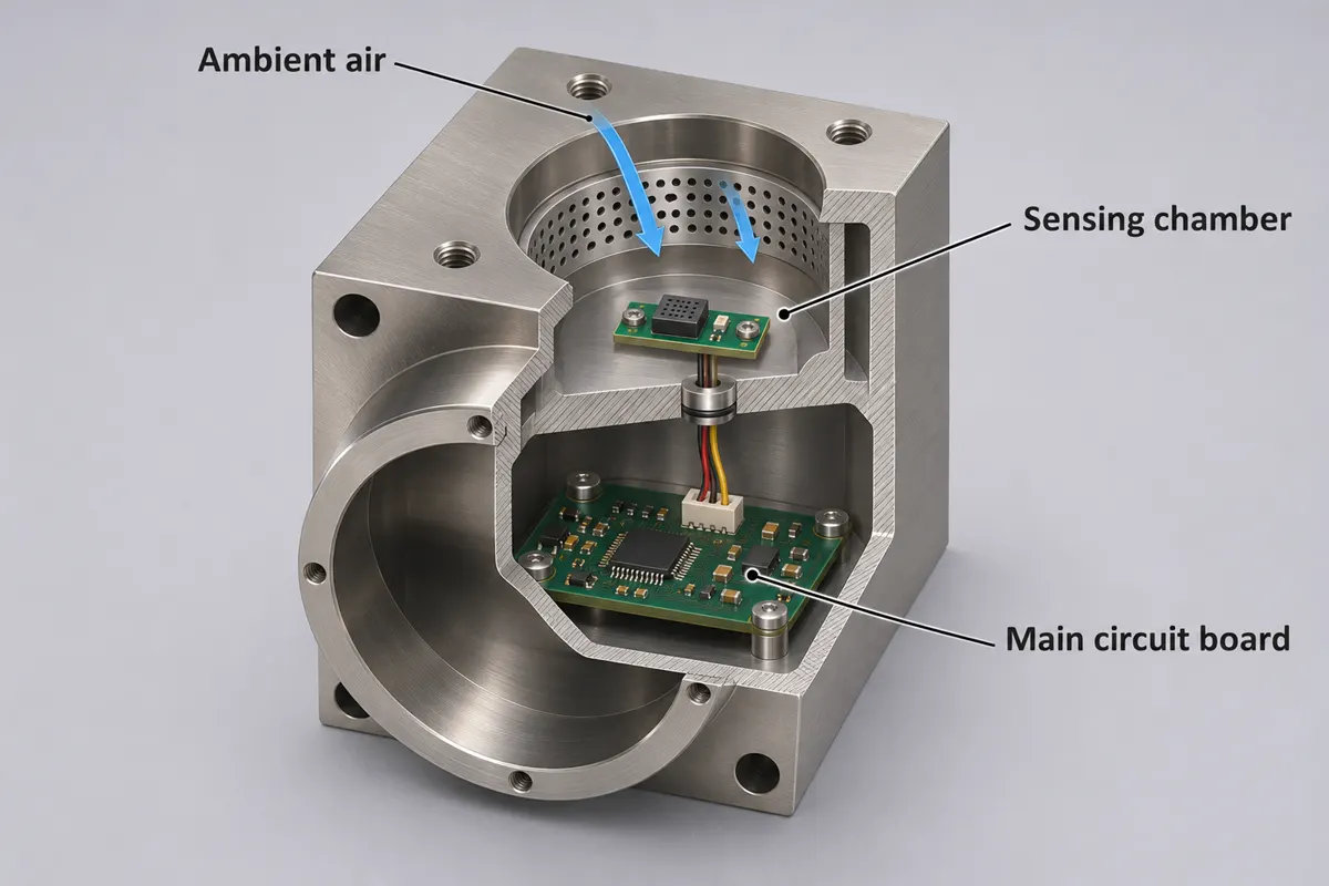

Sensor housing design starts with the sensing interface, the mounting points, and the operating environment. Build the enclosure around those requirements, then choose the material, manufacturing process, and inspection plan. For industrial equipment, the housing has to protect the components, hold them in position, and keep the sensor’s access to what it measures.
Define What the Sensor Housing Has to Do
Fix the sensing element’s working position before drawing the outer shell. A housing for an ambient humidity sensor has different demands from a machined body that locates a sensor module in an inspection station. For humidity and temperature sensors, Sensirion’s design guide recommends a small, separate sensor compartment, openings that exchange air with the surroundings, and thermal decoupling from heat sources on the board. A tightly closed electronics compartment can therefore be the wrong place for a sensor meant to measure room air.
Build the design brief around the actual sensor and equipment, and take installation limits from the selected sensor’s documentation:
- Sensing area, required exposure, and the manufacturer’s installation clearances
- Mounting location, available space, and surrounding components
- Temperature changes, liquids, dust, cleaning chemicals, and expected mechanical loads
- How technicians will install and service the sensor, connector, and cover
Design the Interfaces Before the Outer Shape
Settle how the sensor sits inside the housing and how the housing attaches to the equipment before assigning critical dimensions.
Sensor Location and Equipment Mounting
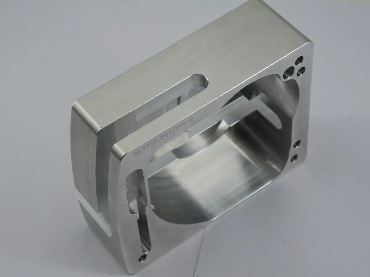
Identify the bore, shoulder, pocket, or mounting face that locates the sensor, and relate its position to the equipment mounting interface with drawing datums where the assembly needs geometric control. A bore diameter sets only size, so the drawing also has to state any position or orientation the assembly depends on. Put tighter controls on features that affect sensing position, mating fit, or sealing, and give noncritical outside surfaces tolerances suited to their function. An engineering drawing that separates these features gives the machinist and inspector a clearer target than one tight tolerance across the whole housing.
Cable and Connector Interfaces
Select the actual connector or cable gland before finalizing its opening, and check its drawing for the panel interface, thread, sealing arrangement, and assembly space. LAPP states that a cable’s outside diameter should fall within the gland’s clamping range to provide strain relief and the specified IP protection class. Model the installed connector and cable, including the room needed to tighten or unplug them. An opening can accept the connector body and still leave too little room to secure its locknut or turn its coupling.
Sealing Faces and Service Access
Design the O-ring groove from the selected seal and the application conditions. Parker’s O-Ring Handbook treats gland geometry, compression, surface condition, and material compatibility as connected inputs, so recheck the groove whenever the seal size or joint arrangement changes. Specify the surface requirements the seal needs, keep sealing faces free of burrs and damage, and review the cover, joint, and fasteners together so the assembled condition matches the seal design.
For a serviceable enclosure, include the cover’s removal path in the assembly model. Check fastener access with nearby machine components in place, and leave a practical route for replacing the sensor without disturbing unrelated equipment.
Choose Materials for the Actual Exposure
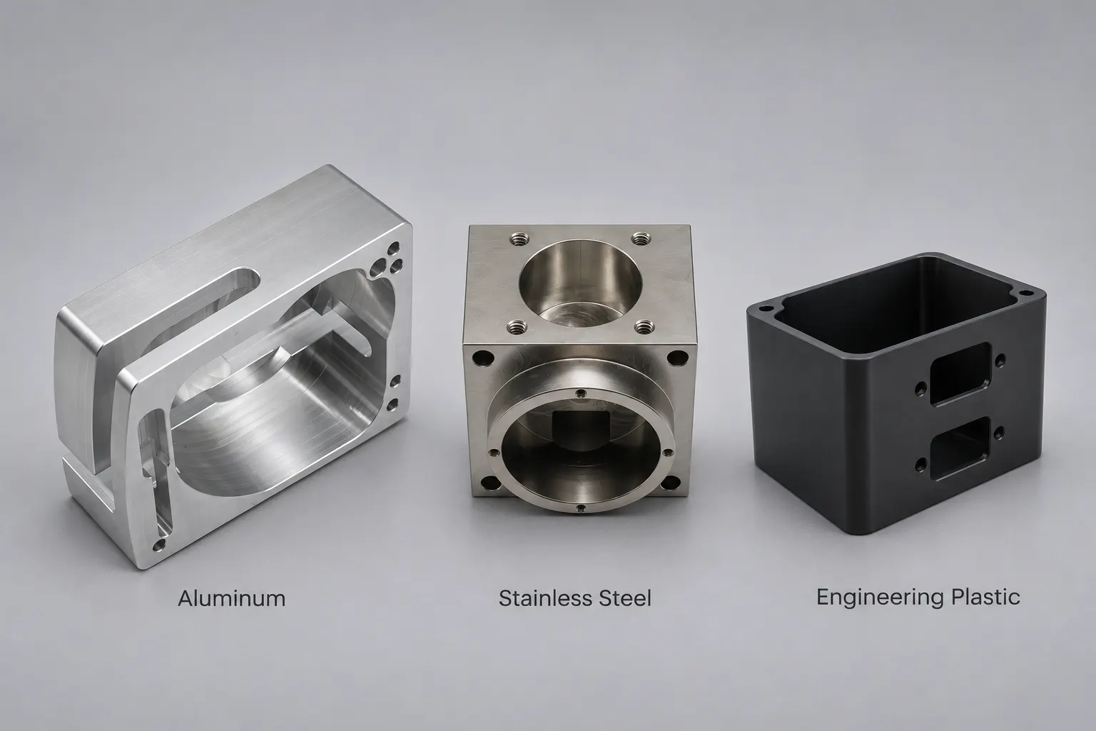
Choose the housing material for the environment and for what its interfaces have to do. Weight, corrosion resistance, electrical insulation, and machining behavior can point to different materials for two housings with the same outer dimensions.
| Material Family | Useful Design Needs | Resolve Before Specifying |
|---|---|---|
| Aluminum | Low-weight machined bodies, pockets, and mounting features | Alloy, exposure, finishing, and the dimensions required after treatment |
| Stainless steel | Mechanically strong housings where corrosion resistance is a selection factor | Grade, actual chemicals, concentration, temperature, and surface condition |
| Engineering plastics | Insulating components and machined polymer housings | Exact polymer grade, chemical and temperature limits, stiffness, and dimensional behavior |
Stainless steel needs more detail than the family name. Outokumpu’s corrosion guidance asks for the medium, concentration, impurities, and temperature, and notes that laboratory tests are not strictly comparable with actual service conditions.
Pick the finish at the same time as the material. For an aluminum housing, review anodizing against the mating dimensions and any surfaces that need masking. Stating whether critical dimensions apply before or after finishing keeps the machining and finishing teams on the same drawing.
Match the Process to the Housing Geometry
Choose the process from the features that control function and the expected order volume:
| Process | Fits When | Check Before Choosing |
|---|---|---|
| CNC machining | The housing needs specified metal or polymer stock, machined locating features, threaded ports, or accurately related mounting faces | Deep cavities, thin walls, internal corner radii, and a setup plan for features on several faces |
| Fabricated sheet metal cover | The job centers on enclosing space around a module | The locating and sealing requirements the formed cover still has to meet |
| Cast shell | The design is stable and headed for production | Tooling, finishing, order volume, and which critical features need secondary machining |
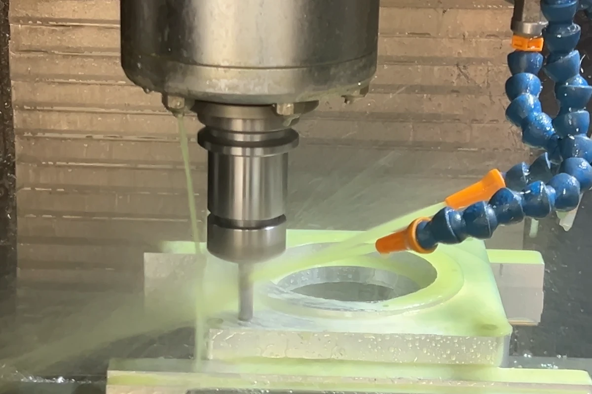
On a machined housing, turning suits rotational bodies and milling forms pockets, flats, and mounting faces. Review deep cavities, thin walls, and internal corners before releasing the model. Thin walls can deflect during cutting, deep and narrow pockets restrict tool access, and an end mill leaves a radius in internal corners. Opening up access, changing the pocket, or splitting the housing into parts can solve these problems, depending on the assembly.
During prototype-to-production planning, decide what the next sample has to prove. A geometry sample can settle installation space, while tests that depend on material properties need the production material and process.
Use DFM and Inspection to Control the Finished Part
Bring geometry, finishing, and measurement into the same design for manufacturability (DFM) review. That review ties the sensor’s functional interfaces to the operations and checks that deliver the housing.
Review Geometry and Finishing Together
Rollyu Precision offers 3-, 4-, and 5-axis CNC milling, turning, and rapid prototyping, with finishes including anodizing, powder coating, and polishing. Engineering teams can review a housing’s locating bore, side port, mounting faces, and surface treatment in one manufacturing brief.
Use the DFM review to work through tool access, thin sections, internal radii, tolerance priorities, and finishing before cutting starts. Ask which features the machinist will cut in one setup and which need another. Where coating or anodizing affects a mating surface, agree on the finished dimensions and masking.
Inspect the Features That Control Assembly
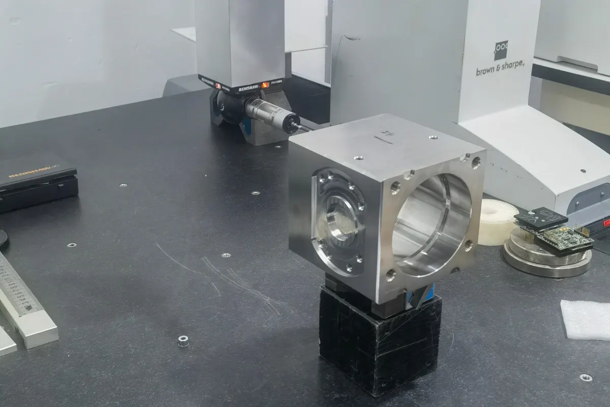
Build the inspection scope around the housing’s locating, mounting, threaded, and sealing features, and match each measurement method to the feature and its drawing requirement, including checks after finishing. Dimensional inspection confirms the checked geometry only. Leak performance, environmental protection, and sensor accuracy need their own verification. Define who performs those checks and what the housing order includes.
Rollyu Precision’s automation manufacturing capabilities include sensor housings and sensor enclosures. Its quality resources include coordinate measuring machine (CMM) inspection, dimensional checks, surface finish inspection, and material traceability. Agreeing on the required records and acceptance features at the start lets the inspection package answer the engineering team’s actual questions.
Prepare the Housing for Manufacturing Review
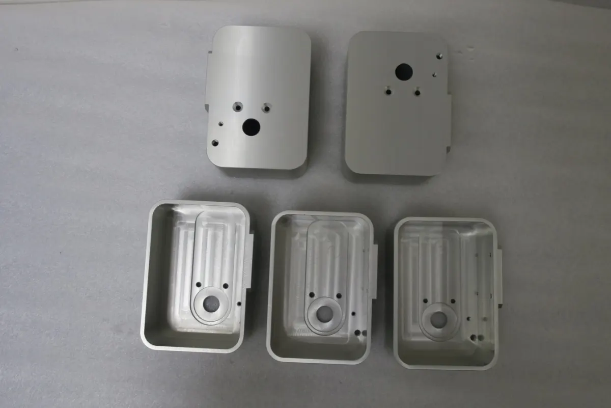
For a custom sensor housing, send the CAD model and controlled drawing together for a CNC machining review, with an assembly view showing the sensor, connector, and equipment mounting. The submission should identify:
- Material grade, drawing revision, prototype quantity, and expected production quantities
- Critical locating and mating features, threads, and seal component references
- Surface finish, masking, visible surfaces, and finished-dimension requirements
- Requested inspection records, and whether delivery covers individual parts or an agreed mechanical assembly
Include the operating conditions with the geometry. Rollyu reviews the manufacturing scope against those inputs, while the engineering team keeps responsibility for the sensor’s application requirements and system validation.
Frequently Asked Questions
Can I Modify a Standard Enclosure Instead of Making a Custom Housing?
Yes, when its size, material, and existing interfaces suit the application. Enclosure makers such as Hammond offer modifications including cutouts, punched and tapped holes, and stud and hinge changes. Before commissioning a new housing, compare the complete modified assembly with the sensor’s requirements and confirm the modification and finishing scope with the supplier.
Can I Drill Cable Entries Into an IP-Rated Sensor Enclosure?
You can, but the enclosure’s original rating may not cover the modified configuration. A new opening adds a component and a sealing interface whose installation affects protection. UL evaluates rated accessories for their ability to maintain the Type or IP rating while mounted to a rated enclosure. Follow the enclosure and accessory instructions, and confirm what evidence supports the completed assembly’s rating.
Will a Sealed Sensor Enclosure Stop Condensation?
No. Moisture trapped inside can condense as temperatures change, and GORE notes that even a sealed, nonvented enclosure eventually admits moisture through seals, cable connectors, or diffusion through the housing walls. A membrane vent lets water vapor leave and equalizes pressure differences, although it cannot stop all condensation. Select the vent for the exposure and installation conditions, then verify the completed design.
Sources
- Design Guide for Humidity and Temperature Sensors, Version 2 (2024), Sensirion: Sensor compartments, air exchange, and thermal decoupling in housings.
- O-Ring Handbook, Parker Hannifin: Seal selection, static gland design, and sealing surfaces.
- Cable Glands, LAPP: Clamping range, strain relief, and IP protection class.
- Corrosion Tables, Outokumpu: Information needed for material selection and the limits of laboratory corrosion data.
- Anodized Aluminum FAQ, Aluminum Anodizers Council: Dimensional change and masking during anodizing.
- Modification Services, Hammond Manufacturing: Examples of standard enclosure modifications.
- Environmental-Rated Accessories for Enclosures, UL Solutions: Mounted accessories and enclosure Type and IP ratings.
- FAQ: GORE Protective Vents, W. L. Gore & Associates: Condensation, vapor transfer, and pressure equalization.