
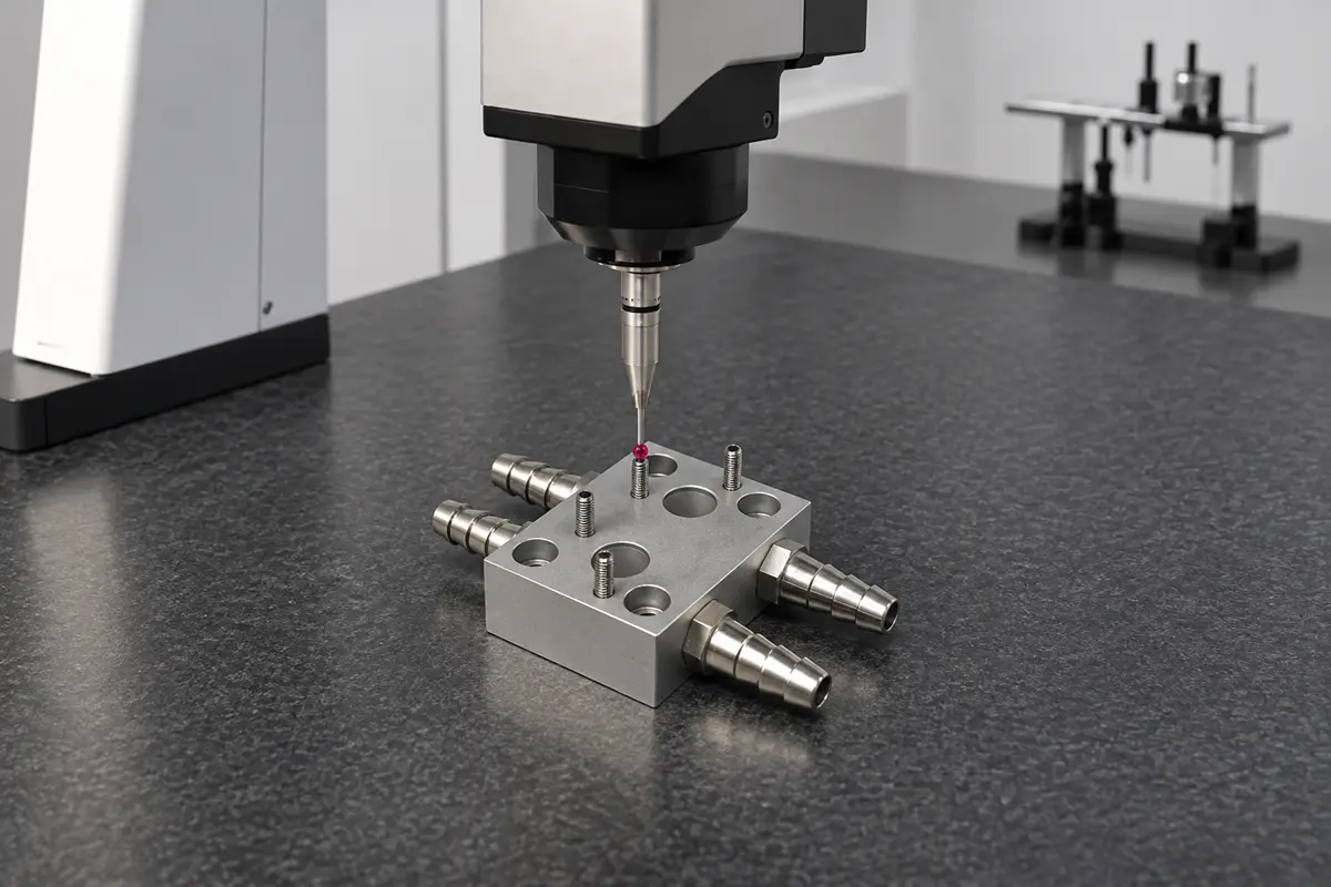

Design a hydraulic manifold block so the shop can drill each oil passage from an accessible face and inspect the intersections before the drill openings are plugged. The block routes fluid between valves and external connections through passages drilled in a solid body. Once the circuit and valves are selected, lay out two paths: the one the oil takes in service and the one the drill takes during machining.
Lay Out Oil Passages Around Drill Access
Every internal passage has to be reachable by a straight drill from an outside face, and every drill opening that is not a working port ends up plugged. Plan the drill path, the intersection depth, and the plug bore together for each passage.
Drill Paths and Entry Faces
Start with the passages that are hardest to reach. Trace each connection from the hydraulic schematic to its valve cavity or external port, then find the face that gives the drill a straight approach. Extending each drill path to the outside of the block in CAD shows whether a mounting hole or another passage sits in the way.
A longer passage of the same diameter makes drill guidance and chip evacuation harder. A small drift at the far end can change how the holes meet or thin the wall between the passage and the next feature. Eaton’s Vickers cartridge-valve reference advises against drill depths greater than 25 diameters. If the layout allows, an entry from a nearer face shortens the cut. Check that position against mounting features, leave room for the plug installation tool, and agree on the drilling approach with the shop before fixing the layout.
Intersection Depth
Take a main passage drilled from the side of the block to meet a shorter hole from the top. The side opening exists only to admit the drill and will receive a construction plug, while the top opening may be a working port. Show the intersection in section and dimension the depth from the entry face. Where the full bore has to reach the intersecting passage, specify the full-diameter depth, which Eaton’s reference measures to the corner of the full diameter rather than to the drill point. The drill point still needs clearance beyond that depth.
Plug Bores
Treat the plug bore as part of the design. A plug can have its own seat, installation depth, and requirements for the surrounding metal, so take them from the selected plug’s installation drawing and show the installed plug in the section view. For the side-drilled example, confirm that the plug closes the drill opening and leaves the connection to the top hole clear.
Design Valve Cavities, Ports, and Sealing Faces Together
Take each interface’s geometry from the mating component’s drawing rather than from a generic hole callout:
| Interface | Drawing Reference | Geometry That Controls Fit |
|---|---|---|
| Screw-in cartridge valve | Valve maker’s cavity drawing for the selected model | Thread, stepped bore, locating shoulder, sealing diameters, and where the drilled passages enter |
| Threaded fitting port | Applicable port drawing for the selected fitting and seal | Thread form, sealing seat or spotface, and the required depth |
| Surface-mounted valve | Valve maker’s mounting pattern | Port locations relative to the mounting holes, plus flatness and finish where the valve seals |
Cartridge Valve Cavities
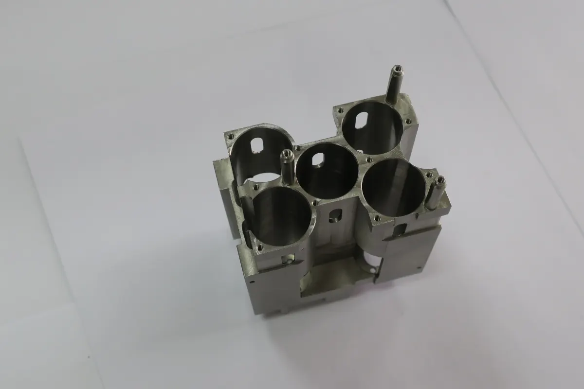
A screw-in cartridge valve fits a stepped cavity, and its locating shoulder sets the cartridge’s installed position. The cavity diameters and port regions have to match the cartridge’s seals and flow openings at that position. Locate each drilled connection within the port region shown on the valve maker’s cavity drawing. In section, check that a side passage enters the intended region without cutting into a surface the cartridge seal uses.
Fitting Ports
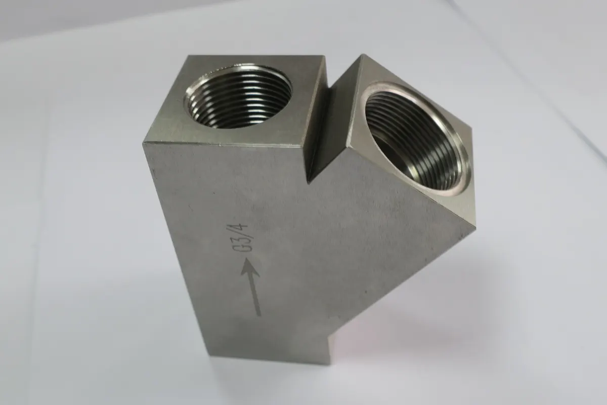
A fitting port’s geometry depends on how the fitting seals, so carry the applicable port detail onto the manufacturing drawing or reference it there. For a fitting that seals at the face with an O-ring, show the sealing seat and any spotface, the flat machined area around the opening, that the fitting requires.
Valve Mounting Faces
On a valve mounting face, a port can have the right diameter and still miss its mating opening if the pattern is out of position. Use the drawing’s functional references, or datums, to tie port locations to the features that locate the valve. Specify flatness and finish where the valve seals so the shop can inspect those characteristics separately.
Inspect Internal Features Before Closing the Passages
Keep an inspection path open until the internal work is complete. When the side drill breaks into the top hole, it can leave a burr on the hidden edge of the intersection, and an external edge break never touches that edge. While the access hole is open, the shop can still clear chips and, where the geometry permits, reach or inspect the intersection. If the critical edge is hard to see or reach, settle the deburring and inspection method before releasing the drawing.
Define the evidence each check has to produce. Dimensional inspection confirms accessible bore sizes and locations, thread gauges check thread conformance, and a roughness tester measures surface texture, while visual inspection covers only the surfaces an inspector can see. If the project sets a particulate cleanliness limit, agree on the verification method while the shop still has access to the passages. HydraForce, for example, inspects and cleans its manifold blocks before installing cartridge valves, plugs, and fittings.
Prepare a Hydraulic Manifold Block for Quote
A quote is only as complete as what the shop can see in the package. Show every passage, interface, and added operation it needs to price.
Drawing and Model Package
Send Rollyu Precision a 3D model and a dimensioned drawing at the same revision, together with:
- The circuit schematic, where it helps the shop trace internal connections
- The exact valve, fitting, and plug drawings that define each interface
- A section through each side-drilled passage showing where the full bore ends and where the plug sits
- Hard-to-reach intersections and critical sealing features marked on the drawing
- Material grade, finish, and the inspection records needed with delivery
Rollyu Precision DFM and Inspection
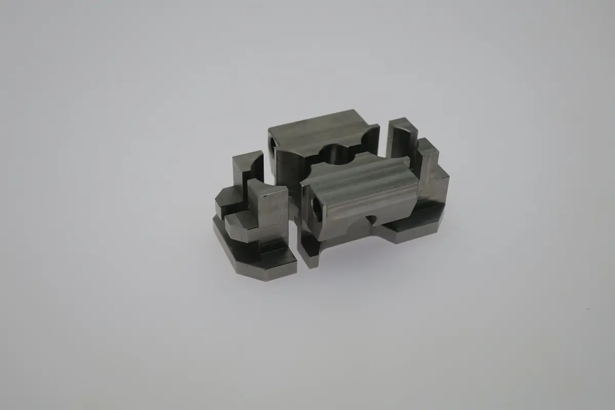
Rollyu machines custom hydraulic manifold blocks for automation equipment, with 3-, 4-, and 5-axis CNC milling for blocks that carry holes and interfaces on several faces. Bring drill-access questions into Rollyu’s design for manufacturability (DFM) review while the layout is still open to change.
The inspection workflow combines in-process checks with final dimensional inspection, and Rollyu’s coordinate measuring machines (CMMs) can check accessible features such as port positions on a mounting face. If your team needs a dimensional report, list the drawing characteristics it should cover. The CNC service handles prototype and production quantities, so engineering can use first-build machining feedback and dimensional results to settle open drawing questions before releasing a batch.
Scope Beyond the Machined Block
State whether the CNC machining quote covers the machined block alone or also plug installation, cleaning to a specified limit, or hydraulic testing. Define the acceptance criteria for each added operation. A hydraulic function or leakage test needs its own method and acceptance criteria, because a dimensional report does not cover it.
Frequently Asked Questions
Can a Hydraulic Manifold Block Be Made From Aluminum?
Yes, within pressure and load limits. Eaton’s Vickers cartridge-valve reference allows aluminum blocks for pressures up to 3,000 psi (210 bar) and recommends Dura-Bar cast iron above that. Have the design engineer confirm the alloy and temper against the operating pressure, loads, and block geometry, including the metal left between passages and around plug bores.
When Is a Standard Valve Subplate Enough?
A standard subplate can work when its mounting pattern, port arrangement, and published operating limits meet the needs of the chosen valve and circuit. A custom block becomes relevant when the circuit needs internal connections or additional valve interfaces that the catalog subplate lacks.
Can a Hydraulic Manifold Block Have Curved Internal Passages?
Yes. Metal additive manufacturing can produce curved internal passages. If the layout depends on a curve, choose the manufacturing route before you finalize the block geometry, and plan how to finish the valve interfaces and verify the internal passages for that process.
Sources
- EATON Vickers Screw-in Cartridge Valves, Technical Reference (2003), Eaton: Full-diameter machining depths, the 25-diameter drill-depth limit, cavity and port details, and the aluminum block pressure limit. Hosted by JJ Hydraulics.
- Metal-to-Metal Sealing of Drilled Holes (2017), SFC KOENIG: Cross-drilled construction openings and the geometry around sealing plugs.
- How Are Deep Holes in a Hydraulic Manifold Made?, Machine Tools (India) Limited: Drill reach, cross-hole intersections, and the burr left at breakthrough.
- Custom Manifolds, HydraForce: Inspecting and cleaning blocks before installing cartridge valves, plugs, and fittings.
- Sub-Plates, HydraForce: Catalog options for mounting hydraulic valves.
- Hydraulic Manifold Case Study, Renishaw: A metal additive manufacturing example with internal passageways and machined interfaces.
- Hydraulic Manifold Block, Famic Technologies: How schematic connections, drill rules, and closure details carry through to production drawings.