
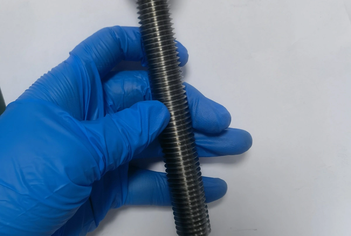

Select thread types for CNC parts from the mating assembly first, then check the feature geometry and manufacturing limits. A correct thread callout prevents a shop from guessing whether a feature must fasten, seal, transmit motion, or mate with an existing component.
Start with the released mating hardware or interface requirement. Then define the thread family, size, pitch, fit, direction, depth, and any finish or inspection condition that affects acceptance. The machining method comes after that decision.
What Does a Thread Type Mean in CNC Part Design?
A thread type is a set of choices, not a single label. The drawing must define where the thread sits, which family or profile it uses, and the geometry that allows it to mate with the intended part.
Thread Location
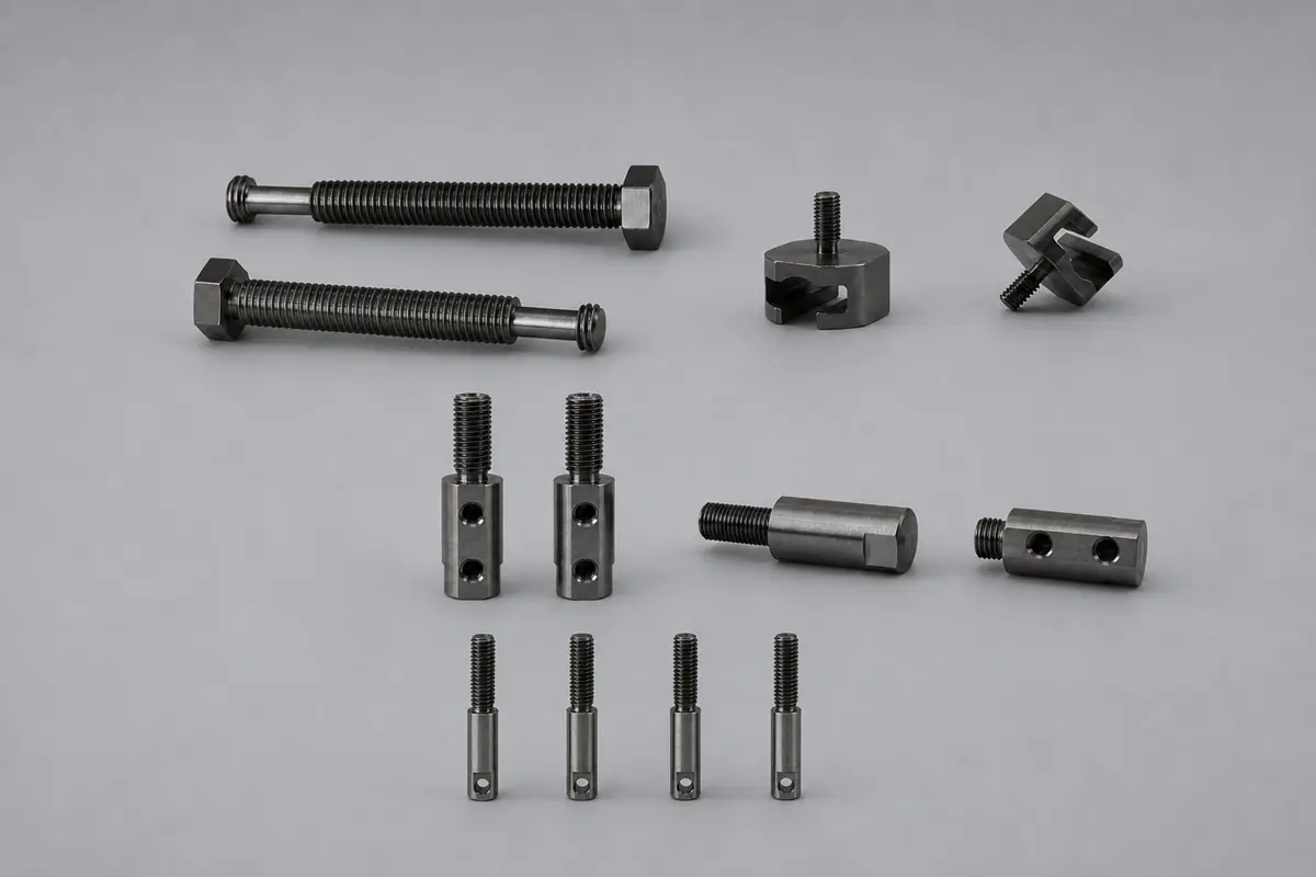
An internal thread runs inside a hole, while an external thread runs on the outside of a shaft, boss, fitting, or fastener. The mating pair needs compatible forms, sizes, pitches, and fit requirements, and the feature needs enough tool entry, thread exit, and inspection access for its location.
Thread Family and Profile
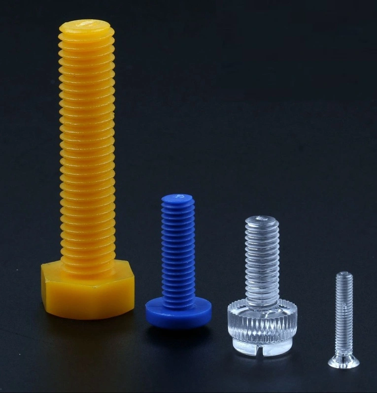
The thread family should match the hardware, drawing package, or interface standard that owns the assembly. ISO metric threads and Unified inch threads cover general-purpose fastening applications, while pipe-thread and motion-thread profiles serve different interfaces.
A pipe fitting, lead screw, replacement component, or proprietary mating part can require a form that looks unlike a general fastening thread. Do not replace a released mating-thread definition with a familiar size that only appears close on a drawing.
Pitch, Hand, and Number of Starts
Pitch, thread hand, and the number of starts must match the mating part. A nominal diameter alone does not define the spacing, rotation direction, or helical geometry of the interface.
- Pitch or threads per inch controls the spacing between thread forms.
- Thread hand tells the manufacturer whether the feature tightens with the standard right-hand rotation or needs a left-hand direction.
- The number of starts identifies the count of separate helical paths in the thread.
Which Thread Family Fits the Assembly?
Choose the thread family from the function and the mating component, then define the exact designation on the drawing. The table below is a selection frame, not a substitute for the applicable standard or the released interface specification.
| Thread Choice | Use It When | State on the Drawing | Design Caution |
|---|---|---|---|
| ISO metric or Unified fastening thread | The mating fastener or assembly already uses that system. | Standard or series, nominal size, pitch or threads per inch, internal or external fit, and functional thread length. | Do not mix inch and metric definitions on a mating pair. |
| Coarse or fine variant | The selected thread family and mating hardware call for a particular series. | The full series or pitch, not only the nominal diameter. | Use the released fastener or mating-part requirement instead of choosing by name alone. |
| Tapered or straight pipe interface | A specified fluid or gas fitting uses that interface. | Exact pipe-thread designation, size, taper or straight condition, and sealing requirement from the interface specification. | A pipe connection needs its own thread and sealing definition. |
| Motion thread, such as Acme or metric trapezoidal | A lead screw, actuator, or motion nut requires a power-transmission profile. | Profile, nominal size, lead, number of starts, hand, mating nut, and any permitted backlash. | A fastening-thread callout does not define a motion interface. |
| Nonstandard or legacy thread | The component must mate with an existing or proprietary part. | Controlled drawing, approved gauge data, or a mating sample with the acceptance requirement. | Do not rely on a nominal diameter or an informal description. |
What Design Details Affect CNC Thread Manufacturability?
Thread form alone does not make a feature manufacturable. Tool access, required full-thread length, hole condition, material, and finish scope determine whether the shop can make and inspect the feature as specified.
Access and Thread Runout
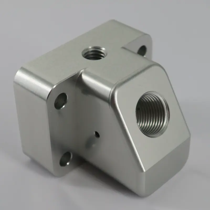
When a shoulder, sealing face, or adjacent feature limits the usable thread length, show the required chamfer, relief, unthreaded clearance, or stopping location. These details let the manufacturer select a toolpath without assuming that the full thread profile can run into a corner or against a shoulder.
Blind-Hole Depth
A blind threaded hole needs a functional thread depth and a separate drill or pilot-hole depth. The additional depth depends on the selected process and tool geometry, so a universal allowance on every drawing can create an unnecessary restriction.
State whether the thread is blind or through, identify the required full-thread length, and show any bottom condition that matters to the mating screw or fastener. A separate depth callout gives the manufacturer room to review chip control, tool entry, and inspection access during design for CNC machining.
Material and Surface Condition
Include the part material, heat treatment, and surface finish in the thread review because they can change tool choice and mating condition. If a coating, anodizing process, plating, or other finish applies near the thread, state whether the dimension and fit apply before or after finishing and identify any area the supplier must mask or leave untreated.
What Should a CNC Thread Callout Include?
A complete CNC thread callout tells the manufacturer what must mate and tells the inspection team what it must verify. Put the information on the controlled drawing or its referenced specification, not only in an RFQ email.
- Thread definition: State the family or standard, nominal size, and pitch or threads per inch.
- Fit and location: State the internal or external condition and the applicable class or fit requirement.
- Functional length: State the threaded length and whether the hole is blind or through. For a blind hole, state the drill depth separately when it controls the design.
- Direction and starts: State left-hand direction or multiple starts whenever the mating part requires either condition.
- Interface conditions: Identify any pipe-fitting, sealing, motion, legacy-component, or mating-sample requirement.
- Finish and acceptance: State finish timing, masked areas, thread gauge requirement, dimensional report, or other acceptance evidence when the assembly needs it.
When Does a Thread Callout Need a Process Note?
Specify tapping, thread milling, forming, turning, or another method only when that process is an approved engineering requirement. Most drawings should define the finished thread geometry and functional acceptance, then let the manufacturer select a capable method during DFM and process planning.
A method note can be appropriate when it protects a known part condition, qualification requirement, or customer-controlled process. A phrase such as “tapped hole“ does not replace the size, pitch, fit, depth, and acceptance information that the finished feature needs.
What Should a Buyer Check Before Releasing an RFQ?
The RFQ package should make the mating requirement visible before programming begins. For custom CNC machining parts, a clear drawing and the right comparison material give the supplier a basis for reviewing thread type, tool access, and verification without making assumptions.
Mating Requirements
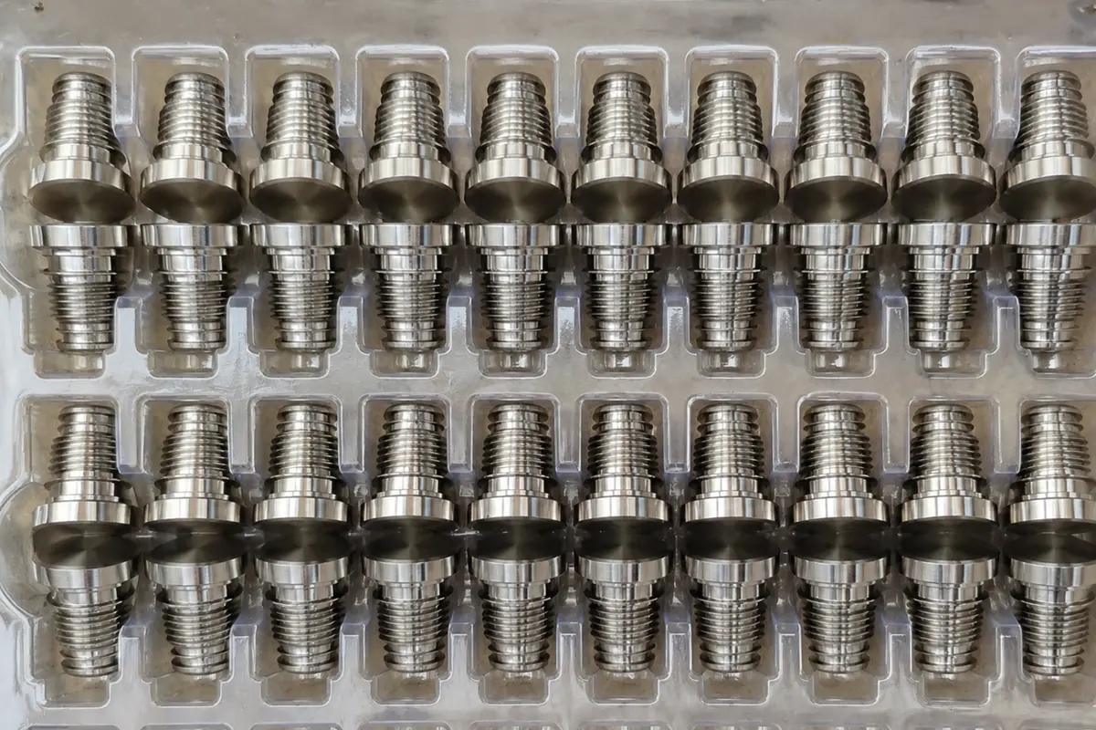
Provide the 2D drawing, 3D model when available, material, finish, quantity, and revision. Add the mating-part drawing, released fastener designation, interface standard, or approved sample when the thread must fit an existing component. For a custom thread, identify whether the function is fastening, motion, sealing, alignment, or replacement compatibility. Rollyu Precision supports CNC machining, DFM review, and threaded features within custom parts, so a complete RFQ gives its engineering team a defined basis for reviewing the feature before production.
Inspection and Documentation
Match the inspection requirement to the thread’s job. A functional thread gauge can check fit, while a critical assembly may also need a defined dimensional measurement, inspection record, or first-article requirement.
Rollyu Precision uses CMM inspection, thread gauges, and in-process and final dimensional inspection for CNC parts. Buyers who need a dimensional report, material record, or other documentation should state the required record and the controlled drawing revision in the RFQ.
Frequently Asked Questions
What Should a Blind Thread Callout State?
Call out the thread family, size, pitch, fit, required full-thread length, and blind condition. State the drill or pilot-hole depth separately when that depth controls the design, then let the supplier confirm the needed clearance for the selected tool and process.
When Should a Drawing Call Out a Left-Hand or Multi-Start Thread?
Call out a left-hand or multi-start thread whenever the mating component requires that geometry. State the direction and number of starts in the controlled thread designation, because a standard right-hand, single-start assumption may not mate with a custom or replacement part.
When Does a Thread Callout Need Surface-Finish Information?
Include the finish condition when it applies to the threaded area or can affect the required fit. The drawing should state whether the dimensions apply before or after finishing and identify any thread area the supplier must mask or leave untreated.
What Inspection Does a Critical Thread Need?
Inspect a critical thread with the method that matches the acceptance requirement. Thread gauges can verify functional fit, while the drawing should define any added dimensional measurement, report, or first-article evidence needed for the assembly.
