
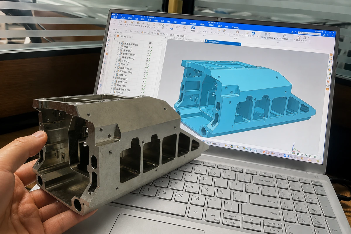

Design for CNC machining means defining a part that a cutting tool can reach, hold, measure, and produce at the required function and cost. Review tool access, setups, tolerances, materials, finishes, and inspection requirements before you release the RFQ.
That review turns a CAD model into a manufacturing package. It gives the supplier enough information to select a machining route and flag conflicts before programming or first-article work begins.
What Does Design for CNC Machining Mean?
Design for manufacturability, or DFM, applies manufacturing limits while the part can still change. For CNC machining, the review asks whether milling, turning, drilling, threading, and inspection can create the required geometry from the selected material.
The goal is to protect the features that control fit, sealing, motion, load transfer, or alignment, while avoiding extra complexity on surfaces that do not affect function.
Which Design Decisions Drive CNC Risk and Cost?
Most CNC quote changes trace back to tool access, part stability, or a requirement that the drawing does not define. Review these decisions together because changing one can affect the setup plan, inspection method, and lead time.
Tool Access, Setups, and Workholding
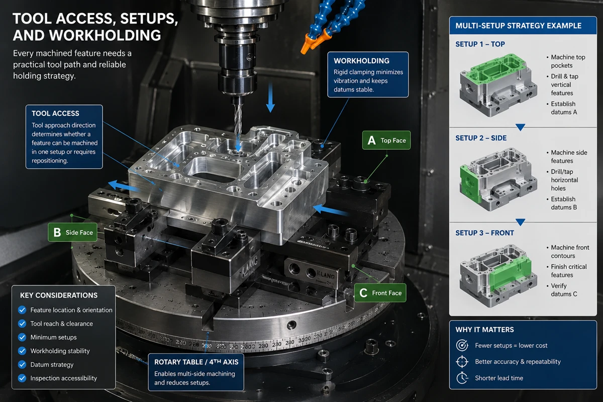
Every machined feature needs a practical tool path and a way to hold the part during cutting. A feature on another face may require a new setup, and a part that needs frequent repositioning can accumulate location risk between operations.
Designing for a single accessible direction can simplify a part, but it is not a universal rule. Angled or multi-face features may justify indexed or simultaneous multi-axis machining when the assembly function needs them. The drawing should identify the functional faces and datums so the supplier can judge whether a different setup strategy is worthwhile.
Pockets, Walls, and Internal Corners
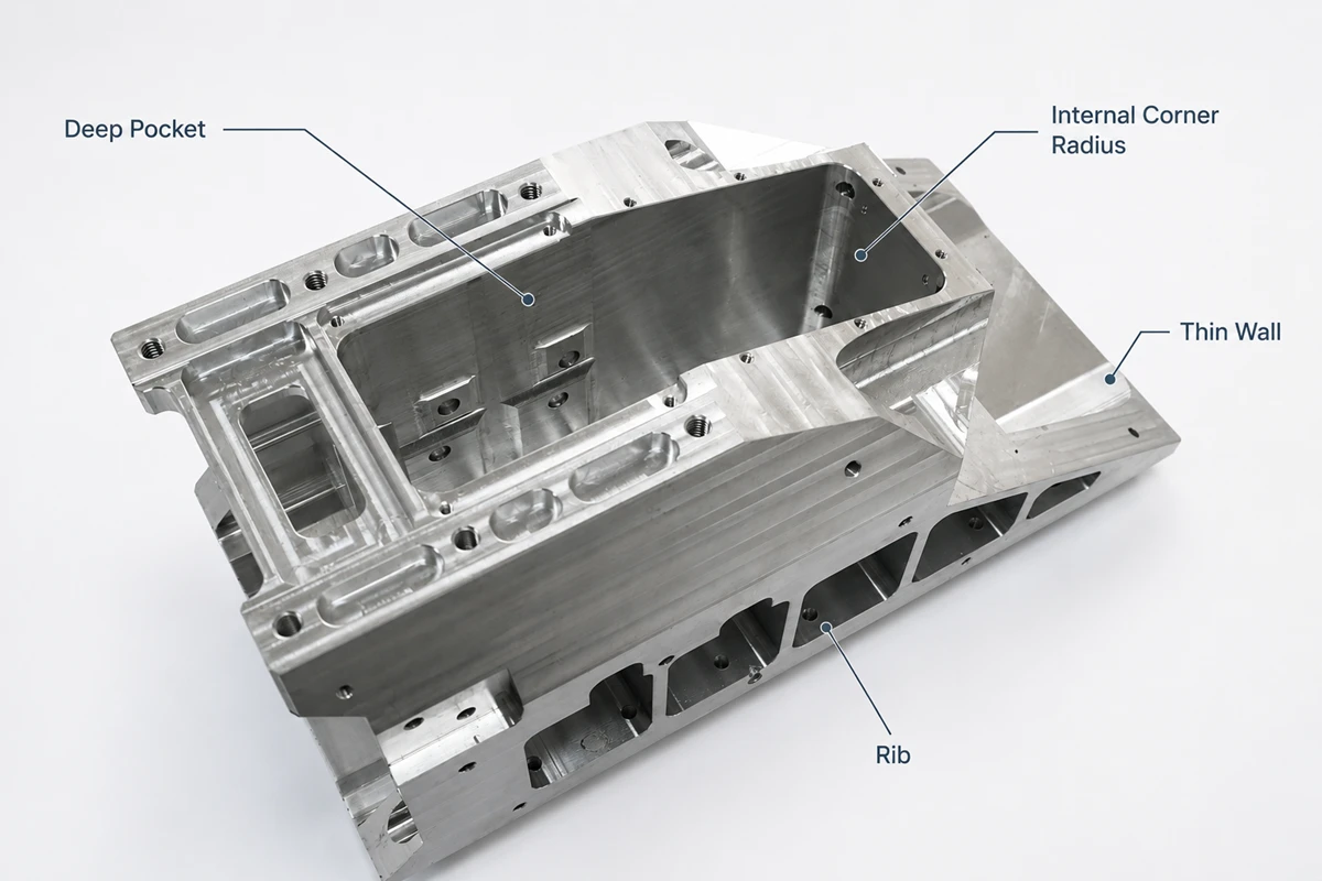
Deep, narrow cavities, tall thin walls, and sharp internal corners deserve an early DFM review. These features can limit tool size, make the part harder to support, or require a longer-reach tool and a more cautious cutting plan.
- Internal corners: Add a radius that works with the required mating part. A cutter cannot leave a perfectly sharp internal corner.
- Pockets: Check depth, width, and entry direction together. A narrow pocket may become difficult when its depth calls for a long tool.
- Walls and ribs: Define the load case before reducing thickness. The supplier needs to know which surfaces are cosmetic, structural, sealing, or only clearance geometry.
Holes, Threads, and Edge Condition
Specify the hole’s job before choosing its callout. A clearance hole, locating bore, threaded feature, counterbore, and sealing port can need different machining and inspection methods even when they appear similar in a model.
Use recognized thread and fastener standards when the assembly calls for them, then state the thread size, class or fit when applicable, depth, blind or through condition, and any insert requirement. Add an edge-break or deburring requirement where a burr could affect handling, assembly, sealing, or a nearby feature. The requirement should remain inspectable rather than relying on a generic note.
Tolerances, GD&T, and Inspection
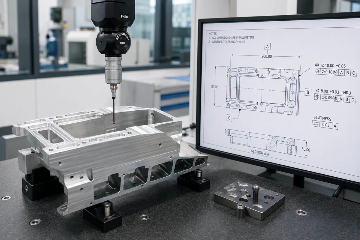
Apply tight tolerances to dimensions that control the part’s function. A bearing seat, locating bore, sealing face, shaft interface, or alignment feature may need a specific dimensional or geometric control, while a nonfunctional outside surface may not.
GD&T can define the datum relationship and geometric condition that a size tolerance alone cannot show. The drawing should also state which characteristics need recorded results and which inspection method matters when it affects acceptance. This prevents a quote from assuming one measurement method while the buyer expects another.
| Design decision | What to define before RFQ | Why it changes the machining plan |
|---|---|---|
| Critical fit or location | Datum scheme, dimension or GD&T control, and mating function | Determines setup references and the inspection approach |
| Internal pocket or corner | Required clearance, corner condition, and tool-entry direction | Determines tool reach and whether the supplier needs a small cutter or added setup |
| Hole or thread | Function, size, depth, tolerance or class, and blind or through condition | Determines drilling, reaming, tapping, threading, or gauging steps |
| Thin or flexible area | Functional load, supported surfaces, and allowable geometry changes | Helps the supplier assess workholding and deflection risk |
| Finished functional surface | Finish requirement, mask area, and whether dimensions apply before or after finishing | Keeps finishing scope and acceptance conditions clear |
How Should Material and Finish Choices Affect DFM?
Material and finishing choices belong in the DFM review because they change the machining route and the dimensions that matter after processing. The supplier needs the exact material grade or an approved alternative, material condition when it affects the part, and the function that drives the choice.
Material-Specific Machining Review
Material selection should follow the part’s load, operating environment, mating components, and manufacturing route. The same nominal geometry may need a different workholding, cutting, or inspection plan when the selected material has a different stiffness, heat response, or machinability.
Do not carry a metal tolerance expectation into a plastic part. Rollyu Precision’s published CNC reference separates metal and plastic tolerance tables, so the drawing and RFQ should identify the actual material before a supplier commits to a tolerance plan.
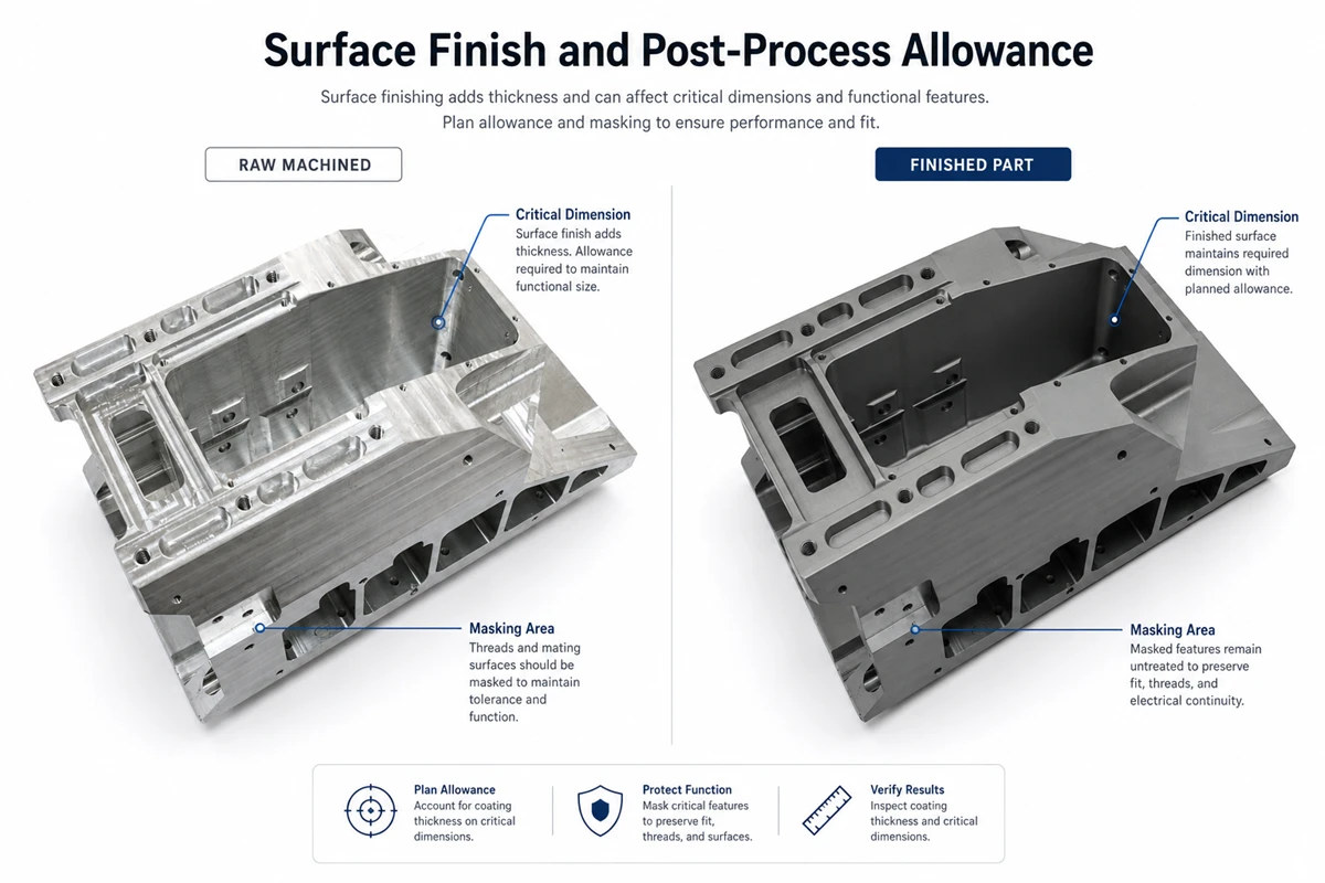
Surface Finish and Post-Process Allowance
Surface finish is a functional requirement when it affects sealing, sliding, appearance, coating adhesion, or contact. Name the relevant surface, the required condition, and the inspection basis instead of adding a blanket finish callout to the entire part.
Finishes and coatings can add or remove material, and they can change the acceptance state of a critical dimension. The drawing should state whether a tolerance applies before or after the finish, identify masking areas, and keep cosmetic requirements separate from functional surface requirements.
What Should an RFQ-Ready CNC Package Include?
An RFQ-ready package gives the supplier the released geometry, the requirements that control acceptance, and the commercial conditions that affect the route. Missing information does not make a part unquotable, but it can make the first quote provisional or cause a later scope change.
Make the Model and Drawing Agree
Send an editable 3D model when available, plus a 2D drawing for dimensions, GD&T, threads, finishes, notes, and revision control. The model and drawing should identify the same revision and resolve conflicts before the RFQ goes out.
The 3D model communicates shape, but it may not express every requirement. If a critical control exists only in an email or a meeting note, move it into the controlled RFQ package so the quote and inspection plan use the same source. STEP vs STL is a useful file-format reference when the team is deciding what to send.
State the Production Conditions
State the material grade, quantity, target delivery date, required finish, and destination. These inputs affect material sourcing, setup planning, outside processing, packaging, and the commercial terms of the quote.
Name any approved material alternative, customer-supplied material, preferred manufacturing method, or no-substitution requirement. Those choices can change the supplier’s available options, so they should be explicit rather than assumed from a previous part.
Define Acceptance and Documentation
Mark the characteristics that need measured results and define the required records before quotation. Depending on the project, the package may call for a dimensional report, Material Test Report, Certificate of Conformance, first article inspection, or a customer-specific format.
For complex datum-based features, state whether the buyer needs a particular report format or measurement output. CMM inspection may be appropriate when the report must evaluate a specified datum scheme and geometric controls.
How Does Rollyu Precision Use DFM Before a CNC Quote?
Rollyu Precision can use DFM review to examine manufacturability, tolerance, cost, and feature risk before CNC programming begins. The review should turn the supplied model and drawing into specific questions about geometry, material, finish, quantity, and inspection scope rather than a generic approval.
Converting Design Constraints Into a Machining Route
For custom CNC machining parts, the machining route may use 3-, 4-, or 5-axis milling, turning, EDM, or a combination of operations when the part’s geometry and requirements support that choice.
Keeping Quote and Acceptance Scope Aligned
Rollyu Precision supports DFM review, CMM inspection, in-process and final dimensional inspection, surface-finish inspection, dimensional reports, Material Test Reports, Certificates of Conformance, and lot-level traceability. Buyers should confirm the project-specific inspection method, record format, sampling requirement, and delivery point because a general capability list does not define part acceptance.
For small validation builds, CNC prototype machining can help teams decide which functional features and records matter before production. When the RFQ is ready for supplier review, the complete package makes it easier to compare supplier feedback on the same geometry and acceptance conditions.
Frequently Asked Questions
Can a 3D CAD model replace a 2D drawing for a CNC RFQ?
A 3D CAD model may define the part geometry, but it may not define every acceptance requirement. Use a controlled 2D drawing when the part needs GD&T, critical dimensions, thread callouts, finish requirements, inspection notes, or a documented revision record.
Should prototype and production CNC parts use the same DFM review?
Both stages need a DFM review, but the questions can differ. A prototype review may focus on functional geometry and fast design feedback, while a production review should also confirm repeatable setups, inspection records, quantity, and any approved process or material controls.
When should a buyer request a DFM review?
Request DFM review before releasing the RFQ, especially when a part has critical interfaces, narrow cavities, thin sections, multiple setups, or project-specific inspection needs. Earlier review leaves room to change the model or drawing before the supplier has programmed the part or committed to the quoted scope.
