

| Quick answer: Machine 304 with a rigid setup, sharp positive-geometry tooling, enough feed to form a real chip, controlled engagement, reliable chip evacuation, and coolant delivered to the active cutting zone. Avoid dwell and repeated light rubbing passes because they can work-harden the surface. |
304 stainless steel is widely specified for food-processing and botanical-extraction equipment, laboratory instruments, medical-equipment hardware, photonics assemblies, robotics, motion-control systems, and general industrial machinery. Designers value its corrosion resistance, toughness, weldability, clean appearance, and broad availability.
The same properties that make 304 useful in service also make it demanding in production. It conducts heat less effectively than many carbon steels, deforms readily at the cutting edge, forms long adhesive chips, and work-hardens when the tool rubs rather than cuts. The result can be built-up edge, rapid tool wear, burrs, dimensional drift, poor surface finish, or broken taps if the complete process is not controlled.
Successful 304 stainless steel machining is therefore not about copying one spindle speed from an online chart. It requires coordinated decisions about material condition, tooling, cutting engagement, feed, coolant, chip evacuation, workholding, feature sequence, deburring, finishing, and inspection. This guide explains the production logic Rollyu Precision uses when reviewing 304 stainless steel machined parts from prototype through repeat production.
What Is 304 Stainless Steel?
AISI 304 (UNS S30400, commonly EN 1.4301) is an austenitic chromium-nickel stainless steel. It is often called “18/8” stainless because its composition is commonly centered around approximately 18% chromium and 8% nickel. Chromium supports formation of a passive oxide film that provides good general corrosion resistance in many atmospheric, food-handling, and mildly corrosive environments.
304L (UNS S30403, commonly EN 1.4307) is a lower-carbon variant often considered when welding or sensitization risk matters. Material grade, product form, mill condition, cold work, certification, and applicable material specification should be defined on the drawing or purchase order. Writing only “304” may be insufficient when traceability, welding, corrosion exposure, or regulated documentation matters.
| Property / Design Factor | Engineering Significance |
| Microstructure | Austenitic; generally low magnetic response when annealed, although cold work and machining can introduce some magnetic response. |
| Corrosion resistance | Good general corrosion resistance, but not automatically suitable for seawater, brines, or aggressive chloride service. |
| Thermal behavior | Relatively low thermal conductivity concentrates heat near the tool-chip interface. |
| Work hardening | High; rubbing, dwell, runout, or repeated shallow passes can create a hardened surface layer. |
| Ductility and toughness | Useful in service but contributes to stringy chips, burr formation, and adhesive behavior during cutting. |
| Weldability | Generally good; 304L may be preferred for welded assemblies depending on the code, section thickness, and service conditions. |
Why Is 304 Stainless Steel Difficult to Machine?
Work Hardening
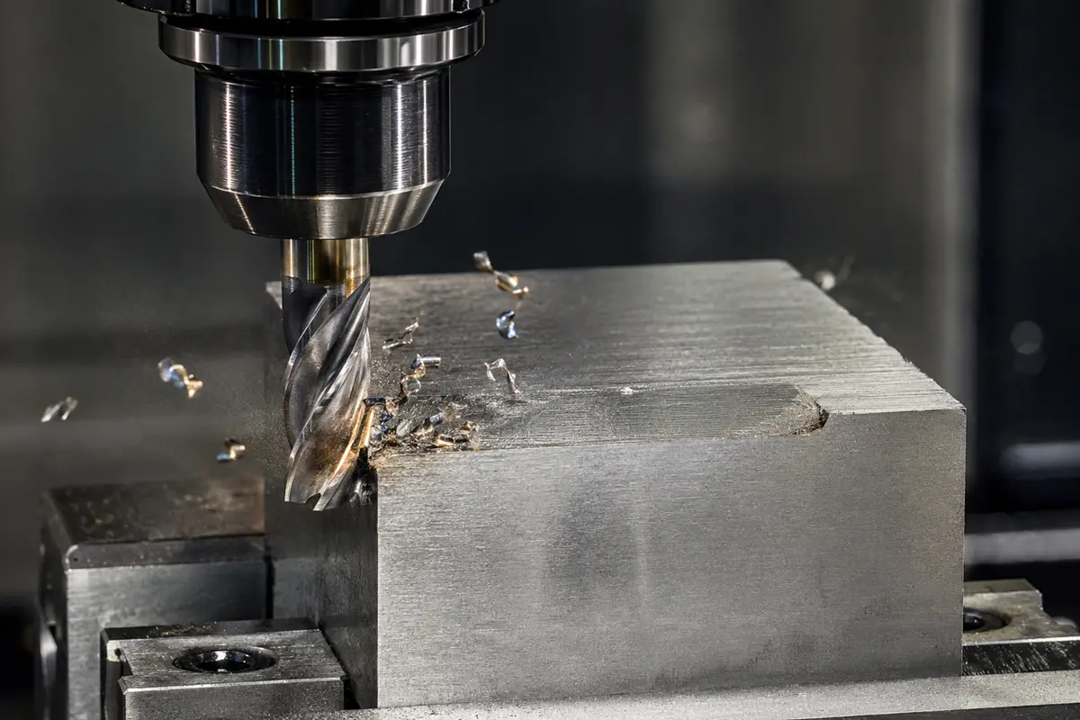
304 can harden quickly under plastic deformation. A dull edge, excessive runout, insufficient chip load, or a pause in the cut may polish and deform the surface instead of removing material. The next tool pass then meets a harder layer, increasing cutting force and heat. The practical response is to keep the edge cutting decisively beneath the affected skin and avoid unnecessary dwell or repeated spring passes.
Heat Concentration and Tool Wear
Because 304 transfers heat away from the cutting zone relatively slowly, a large share of the heat remains near the insert or end mill. Excess temperature promotes adhesion, flank wear, plastic deformation of the cutting edge, and dimensional instability. Toolpath engagement and coolant access can matter as much as nominal cutting speed.
Stringy Chips and Built-Up Edge
The alloy’s ductility encourages continuous chips. These can wrap around a tool or part, scratch completed surfaces, obstruct coolant, and interrupt automated cycles. If material adheres to the cutting edge and later tears away, it can damage the surface and change the effective tool geometry. Chipbreaker selection must match the actual feed and depth of cut, not simply the material name.
Burr Formation and Distortion
Ductility and cutting pressure can create heavy exit burrs around cross-holes, slots, thin edges, and threads. Thin-wall parts can also move when clamping force, residual stress, or asymmetric material removal is released. Feature sequencing, support, balanced roughing, predictable finishing stock, and inspection after unclamping all matter.
How to Machine 304 Stainless Steel Successfully
Build a Rigid Cutting System
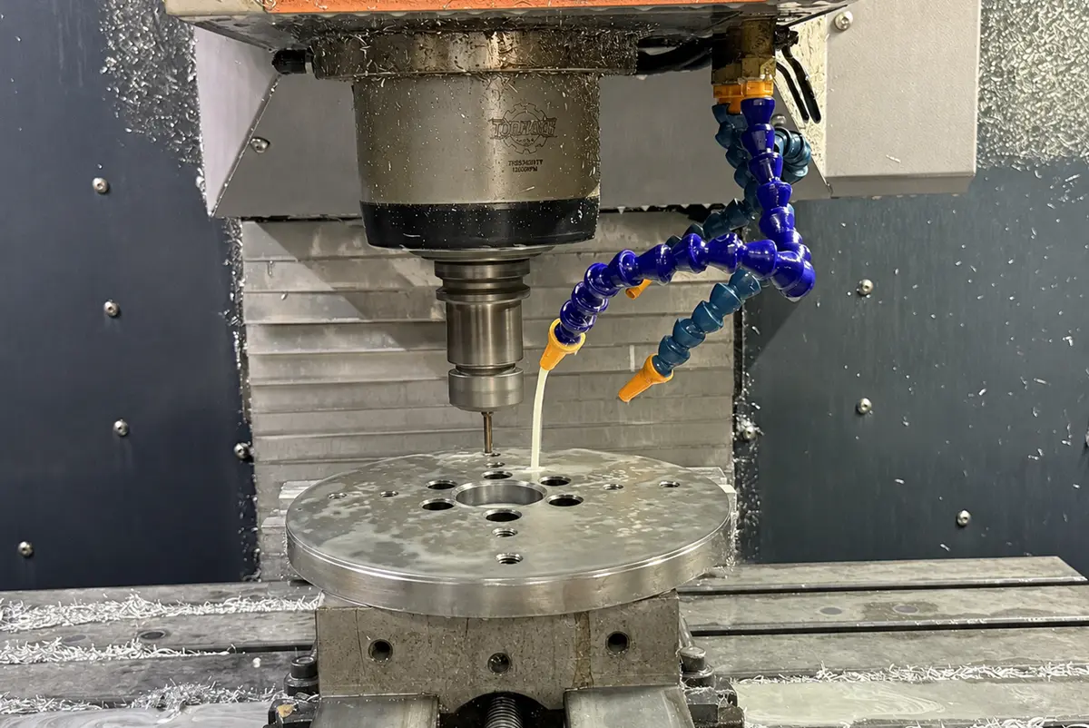
Minimize tool overhang, verify runout, support thin walls and slender shafts, and ensure fixtures contact the intended datums. For plates and housings, distribute clamping force so the workpiece remains stable without being distorted. For turned parts, select jaws, collets, guide bushings, or steady support according to the length-to-diameter ratio, concentricity, and surface-protection requirements.
Use Sharp, Positive-Geometry Tooling
Coated carbide is a common production starting point for milling and turning. Positive rake and free-cutting geometry help reduce force and heat, while the edge preparation must remain strong enough for the engagement and interruption level. Tool substrate, coating, chipbreaker, nose radius, and edge treatment should be selected for the actual operation; blanket rules such as “always use PVD” or “always use CVD” are not reliable engineering guidance.
Maintain a Decisive Feed
Feed must be high enough to form a real chip without overloading the edge. Avoid dwelling at the bottom of a hole, pausing on a turned diameter, or repeatedly skimming a work-hardened surface. Where a finish pass is needed, leave a controlled allowance and use a stable, sharp tool.
Control Heat and Remove Chips
Use consistent flood or through-tool coolant when appropriate, directed at the active cutting zone. Deep pockets, small bores, blind holes, internal threads, and parting operations need particular attention. Recutting trapped chips quickly damages the edge and finished surface.
Keep Engagement Predictable
Adaptive or trochoidal toolpaths can reduce engagement spikes in deep pockets and slots. Smooth entry and exit moves limit shock. On rigid CNC equipment, climb milling is commonly used for finishing because it can reduce rubbing, but machine condition, workholding, backlash, and part geometry still govern the final choice.
Starting Cutting Parameters for 304 Stainless Steel
The ranges below are conservative planning windows rather than fixed recipes. They assume annealed 304, a rigid CNC machine, suitable carbide tooling, effective coolant, and stable workholding. Confirm the range with the cutting-tool manufacturer and validate it through controlled trials. Adjust speed, feed, engagement, grade, and geometry according to wear pattern and process stability.
| Parameter conversion: Surface speed must be converted using the actual tool or workpiece diameter. RPM = (Vc × 1000) ÷ (π × diameter in mm). Feed is then calculated from tooth count or revolutions. Never copy an RPM from one diameter to another. |
| Operation | Carbide Starting Window | Feed / Engagement Guidance | Primary Control |
| Turning | Vc 90–180 m/min (295–590 sfm) | Approx. 0.08–0.30 mm/rev, matched to insert and finish | Stable chipbreaker action; avoid dwell |
| End milling | Vc 70–150 m/min (230–490 sfm) | Approx. 0.02–0.10 mm/tooth; lower radial engagement for long tools | Constant engagement and chip evacuation |
| Drilling | Vc 40–90 m/min (130–295 sfm) | Approx. 0.05–0.20 mm/rev, scaled to drill diameter | Positive feed; coolant reaches cutting lips |
| Parting / grooving | Vc 60–120 m/min (195–395 sfm) | Use toolmaker guidance and maintain rigidity | Center height, blade support, coolant access |
| Tapping | Application-specific | Avoid dwell/reversal errors; use suitable lubricant | Correct tap geometry and synchronized motion |
CNC Milling 304 Stainless Steel
Milling plans should balance metal-removal rate with thermal and geometric stability. Use the shortest practical tool, verify holder and spindle runout, and avoid burying the full cutter width in a deep slot when a lower-engagement path is available.
- Roughing: use controlled radial engagement, adequate axial depth, smooth entry, and reliable chip clearance.
- Finishing: leave predictable stock, use a sharp edge, and minimize recutting or repeated light passes.
- Deep pockets: plan chip-clearance moves or through-tool coolant where practical.
- Thin walls: alternate roughing regions, reduce unsupported tool pressure, and verify dimensions after unclamping.
- Grooved plates: control accumulated tool wear and inspect groove width, depth, flatness, and edge condition across the entire pattern.
CNC Turning and Swiss Machining 304 Stainless Steel
Turning requires chip control that remains effective across changing diameters, shoulders, grooves, and interruptions. An insert working below its intended chipbreaking range may produce long, hazardous stringers even when the nominal material grade is correct. For small-diameter Swiss parts, bar straightness, guide-bushing support, tool approach, cutoff strategy, and coolant delivery become especially important.
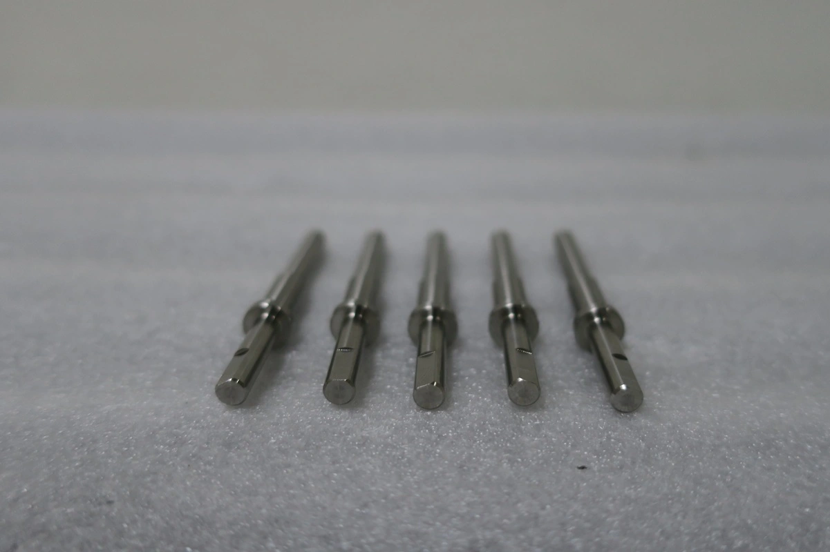
Typical 304 stainless steel turned parts include bearing shafts, leadscrew shafts, rigid couplings, nozzles, adapters, end caps, pins, threaded fittings, and custom fasteners. Process selection should be based on diameter, length, concentricity, thread class, annual volume, and inspection access rather than simply whether the part is round.
Drilling, Reaming, and Threading 304 Stainless Steel
Holemaking failures frequently begin with poor chip evacuation or a work-hardened entry surface. Use tools designed for stainless steel, maintain positive feed, and avoid peck cycles that repeatedly rub the hole bottom. For deep or blind holes, the cycle must create room for chips and deliver coolant to the cutting lips.
Thread milling can be attractive for larger threads, expensive parts, difficult blind holes, or applications requiring diameter adjustment. Tapping can remain efficient for suitable production work, but drill size, tap geometry, synchronization, lubricant, thread depth, and chip space must be planned together. Critical threads should be verified with the specified functional gauges rather than judged visually.
Application Example: 304 Stainless Steel Grooved Filter Support Plate
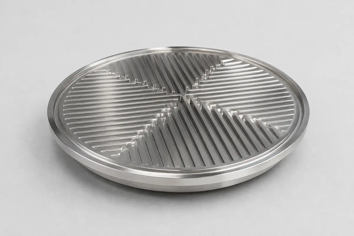
A grooved filter support plate shows why machining 304 stainless steel is more than producing a round disc. In a typical vacuum filtration assembly, the plate sits beneath a filter medium or sintered filter element. Its job is to support the filter, distribute negative pressure across the usable area, and provide drainage paths for the filtrate. The exact assembly and operating conditions must always be verified from the customer drawing and bill of materials.
| Machined Feature | Functional Purpose | Manufacturing Risk to Control |
| Dense parallel grooves | Create multiple filtrate drainage paths | Width/depth variation, burrs, chip packing, tool wear |
| Four-section pattern | Distribute flow across the working area | Uneven engagement and cumulative position error |
| Cross-shaped main channels | Collect flow from individual groove zones | Corner burrs, blend quality, local stress concentration |
| Precision outside diameter / step | Locate the plate in its housing and support sealing | Fit error, distortion, damage during clamping |
| Controlled flatness | Support the filter evenly and reduce bypass risk | Residual stress, asymmetric stock removal, clamping distortion |
| Cleanable surface and edges | Reduce trapped residue and simplify cleaning | Torn finish, sharp burrs, inaccessible groove roots |
Why 304 Is Appropriate for This Component
304 offers a practical combination of general corrosion resistance, cleanability, mechanical strength, temperature capability, availability, and cost for many botanical-processing, laboratory, and food-equipment filtration systems. It can also be passivated and cleaned after machining. However, the process fluid, chloride exposure, cleaning chemistry, temperature, regulatory requirements, and surface-finish expectations must be reviewed before final material approval.
Why CNC Machining Is Required
Stamping a flat disc would not provide the same controlled network of grooves, locating steps, sealing relationships, and flatness. CNC turning can establish the outside diameter, faces, and steps; CNC milling can create the drainage pattern. The manufacturing plan must also include deburring, cleaning, and inspection so groove edges do not damage the filter medium or trap contamination.
Controlling Tolerances and Surface Finish
A drawing should distinguish function-critical requirements from cosmetic preferences. Applying extremely tight tolerances or low roughness values to every surface raises cost without necessarily improving performance. The better approach is to define the datum structure, fits, sealing surfaces, fluid-contact surfaces, and inspection method according to how the part operates.
| Design / Quality Question | What to Specify on the RFQ or Drawing |
| Material | 304 or 304L; material standard; product form; mill certificate and traceability requirements. |
| Datums and GD&T | Functional datum system; flatness, position, perpendicularity, runout, and profile where needed. |
| Surface requirements | Ra only on functional surfaces; polishing direction/grade; passivation or electropolishing specification. |
| Threads and fits | Thread class, gauge requirement, mating condition, press/slip fit, and finishing allowance. |
| Cleanliness | Food, medical-equipment, optical, vacuum, or process-fluid cleaning and packaging expectations. |
| Inspection records | FAI, CMM report, dimensional report, material certificate, surface-roughness record, or lot traceability. |
Passivation, Electropolishing, and Other Finishing Options
Passivation
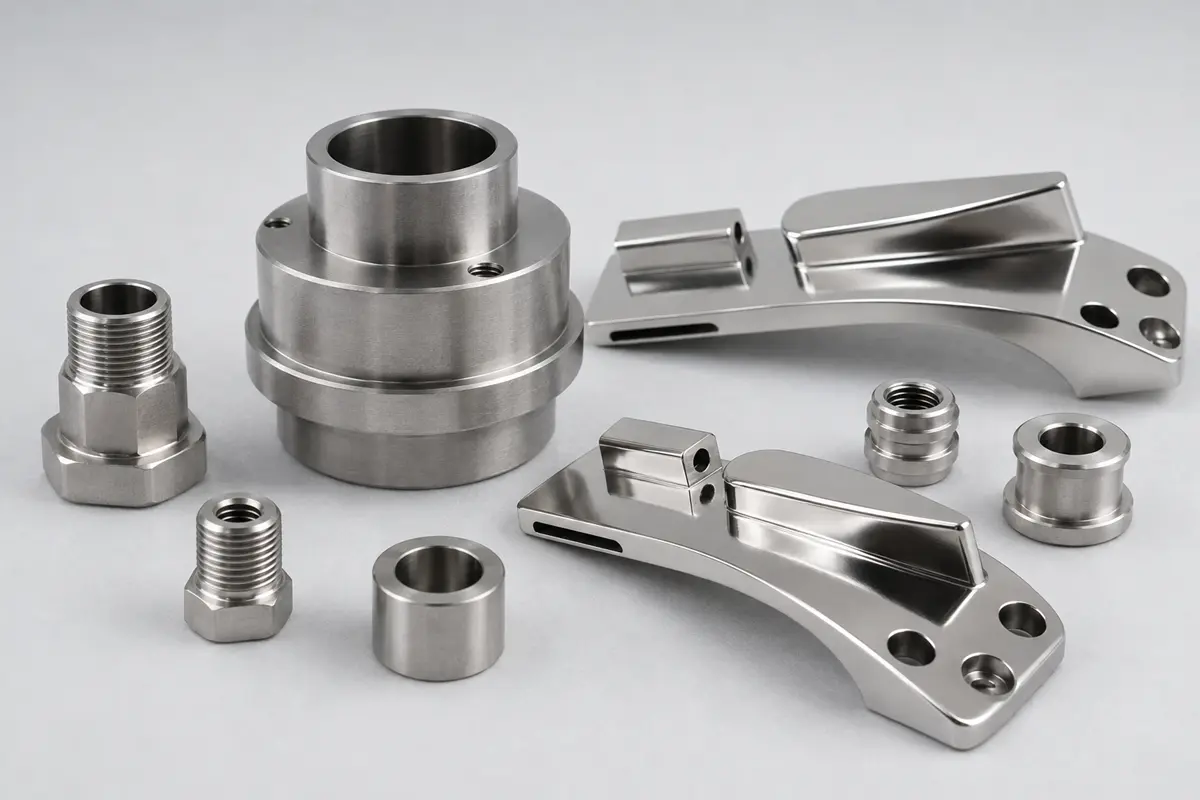
Passivation is a chemical treatment intended to remove free iron and support the stainless steel’s passive surface. It is not a coating and should not be described as adding a controlled thickness. The applicable specification, cleaning sequence, masking, and verification requirements should be stated on the drawing or purchase order.
Electropolishing
Electropolishing removes a small amount of material electrochemically and can improve cleanability, reduce microscopic peaks, and brighten the surface. It also changes dimensions, edges, and thread geometry, so machining allowances, masked areas, inspection timing, and acceptance criteria must be agreed before production.
Mechanical Polishing and Bead Blasting
Mechanical polishing can produce a directional or progressively refined finish, while bead blasting produces a more uniform matte appearance. Neither treatment should be specified only by a marketing term. Abrasive type, target roughness where functional, direction, masking, cleanliness, and visual acceptance standards should be defined.
304 vs. 316, 303, and 17-4 PH
304 is not automatically the best stainless steel for every machined component. Material selection should start from the environment and functional requirement, then consider manufacturing cost. The comparison below is intentionally brief so this article remains focused on machining 304 stainless steel; a dedicated 304 vs. 316 page should address the broader selection query.
| Grade | Why an Engineer May Choose It | Primary Trade-off |
| 303 | High-volume turned parts where machinability is the priority | Lower corrosion resistance and weldability than 304 |
| 304 / 304L | Balanced corrosion resistance, fabrication, availability, cleanability, and cost | Work hardening and chip-control challenges |
| 316 / 316L | Improved resistance to pitting and crevice corrosion in many chloride environments | Higher material cost; still challenging to machine |
| 17-4 PH | Higher strength and hardness after controlled heat treatment | Heat-treatment condition and dimensional change require planning |
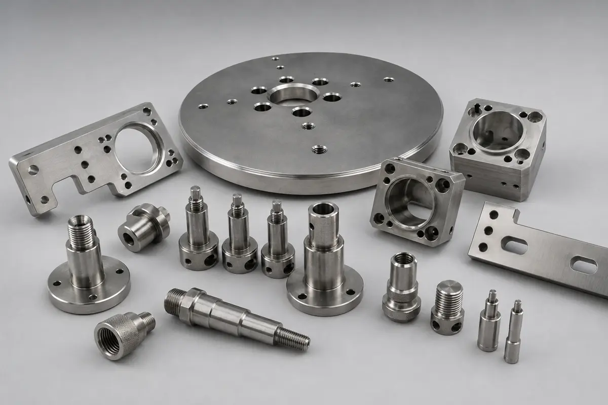
Typical 304 Stainless Steel CNC-Machined Parts
| Industry / Equipment | Example Components | Important Buying Considerations |
| Food and botanical processing | Filter support plates, nozzles, manifolds, adapters, shafts, clamps | Cleanability, corrosion exposure, crevices, surface finish, traceability |
| Medical and dental equipment | Instrument housings, brackets, handles, fixture components | Device classification, cleaning/sterilization, documentation, burr control |
| Laboratory and life-science systems | Fluid plates, sample-handling parts, pump adapters, frames | Chemical compatibility, leak paths, cleanliness, small-batch repeatability |
| Photonics and quantum systems | Optical frames, mounts, vacuum-support hardware | Geometric stability, low burrs, cleanliness, magnetic response where relevant |
| Robotics and motion control | Shafts, couplings, spindles, bearing supports, mounting plates, end caps | Concentricity, fits, wear surfaces, assembly datums, repeatability |
Common Problems and Corrective Directions
| Problem | Likely Contributors | Corrective Direction |
| Built-up edge | Unstable cutting, unsuitable geometry, poor lubrication | Restore true cutting action; verify speed/feed, edge geometry, and coolant delivery. |
| Rapid flank wear | Excess heat, excessive speed, poor grade or engagement | Inspect the wear pattern and optimize speed, grade, engagement, and cooling together. |
| Stringy chips | Feed/depth outside the chipbreaker range | Match chipbreaker and feed; improve evacuation and automation safeguards. |
| Burrs or torn finish | Dull edge, unsupported exit, recut chips, vibration | Use a sharp stable edge, change exit strategy, support the feature, and clear chips. |
| Oversize or tapered bore | Deflection, heat, runout, chip packing | Verify runout and allowance; stabilize temperature; improve clearance; use an appropriate finishing process. |
| Tap breakage | Work-hardened entry, chip packing, misalignment, poor lubricant | Review drill size, tap geometry, synchronization, depth, lubricant, and blind-hole chip space. |
How Rollyu Precision Supports 304 Stainless Steel Projects
Rollyu Precision supports prototype, low-volume, and repeat-production stainless steel projects using CNC milling, 3/4/5-axis machining, CNC turning and Swiss machining, EDM, grinding, deburring, finishing coordination, and dimensional inspection. The correct route is selected from the geometry, tolerance, quantity, finish, and documentation requirements rather than forcing every component through the same process.
- Engineering review of material, datum structure, thin walls, deep pockets, threads, fits, and inspection access.
- Machining plans designed around work-hardening control, tool accessibility, chip evacuation, and stable workholding.
- CMM, optical measurement, height gauges, micrometers, pin gauges, thread gauges, and surface-roughness verification as required.
- Material certificates, dimensional reports, first-article inspection, lot traceability, and controlled packaging when specified.
- ISO 9001:2015 and ISO 13485:2016 quality-management support for demanding industrial and medical-equipment supply chains.
Information Needed for an Accurate Quote
3D CAD model and controlled 2D drawing, including revision status.
Material grade, product specification, stock form, and certification requirements.
Prototype and production quantities, expected annual demand, and delivery schedule.
Critical dimensions, GD&T, threads, fits, and functional sealing surfaces.
Surface roughness, polishing, passivation, electropolishing, marking, and masking requirements.
Inspection reports, FAI, CMM data, material traceability, cleanliness, and packaging requirements.
Frequently Asked Questions About Machining 304 Stainless Steel
Is 304 stainless steel easy to machine?
304 is machinable, but it is less forgiving than free-machining stainless grades such as 303. Its work hardening, heat concentration, ductility, and long chips require rigid setups, sharp tooling, stable feed, effective coolant, and disciplined chip control.
What cutting tools are best for machining 304 stainless steel?
Coated carbide with application-appropriate positive geometry is a common production choice. High-speed steel can still suit certain low-speed tools or low-volume operations. The coating, substrate, chipbreaker, and edge preparation should follow the operation, stability, coolant strategy, and toolmaker guidance.
How do you prevent work hardening when machining 304?
Prevent rubbing. Use a sharp edge, rigid setup, sufficient feed to form a chip, controlled engagement, and continuous cutting without unnecessary dwell. Leave predictable finishing stock so the final tool cuts beneath the affected layer.
Can 304 stainless steel be CNC milled and turned?
Yes. 304 is routinely milled, turned, Swiss machined, drilled, reamed, threaded, ground, polished, passivated, and electropolished. The best route depends on part geometry, tolerance, quantity, surface requirements, and inspection access.
What surface finish can be achieved on machined 304 stainless steel?
The achievable result depends on tool condition, stability, stock allowance, geometry, and any secondary polishing or electropolishing. Specify a numerical roughness only on surfaces where it is functional, together with the measurement method and direction if relevant.
Is 304 suitable for medical parts?
It can suit certain medical-equipment and instrument components, but suitability depends on device classification, patient contact, sterilization method, corrosion exposure, biocompatibility, and governing standards. Do not select 304 solely because a part is called medical.
Is 304 suitable for food-processing and botanical-extraction equipment?
Often yes, particularly where general corrosion resistance and cleanability are required. The final decision must consider product chemistry, chlorides, temperature, cleaning agents, welds, crevices, surface finish, and applicable regulatory requirements.
Should I specify 304 or 304L for a machined and welded part?
304L is commonly considered when welding and sensitization resistance matter. The design or materials engineer should decide using the applicable code, section thickness, fabrication route, service temperature, and corrosion environment.
When should I choose 316L instead of 304?
316L is commonly considered for more aggressive chloride exposure, wet processing, certain cleaning chemistries, or higher corrosion-risk service. It is not universally better; the application, lifetime cost, machining, and compliance requirements should drive the decision.
What information does Rollyu need to quote a 304 stainless steel part?
Send the 3D CAD file, controlled 2D drawing, material specification, quantities, critical tolerances and GD&T, threads and fits, surface finish, passivation or electropolishing requirements, inspection documentation, cleanliness, packaging, and target schedule.
Request a DFM Review and Quote
| Need reliable 304 stainless steel precision machined parts? Send Rollyu Precision your CAD files, drawings, quantities, material specification, critical tolerances, finish, and inspection requirements. Our engineering team will review manufacturability, identify machining and finishing risks, and prepare a project-specific quotation. |
