
A tapped hole uses a tapping tool to cut threads into a pre-drilled pilot hole, while a threaded hole refers to any internal thread regardless of how the manufacturer created it. Specifying the exact thread formation method on your drawings directly dictates CNC machining costs, lead times, and part reliability.
Here is how thread formation methods impact your CNC machining quote, and how to specify them correctly.
What’s the Difference Between Tapped Hole and Threaded Hole?
The real difference sits in how the threads are made, how each type shows up on a drawing, and what engineers actually mean when they use each term.

Thread Formation Methods
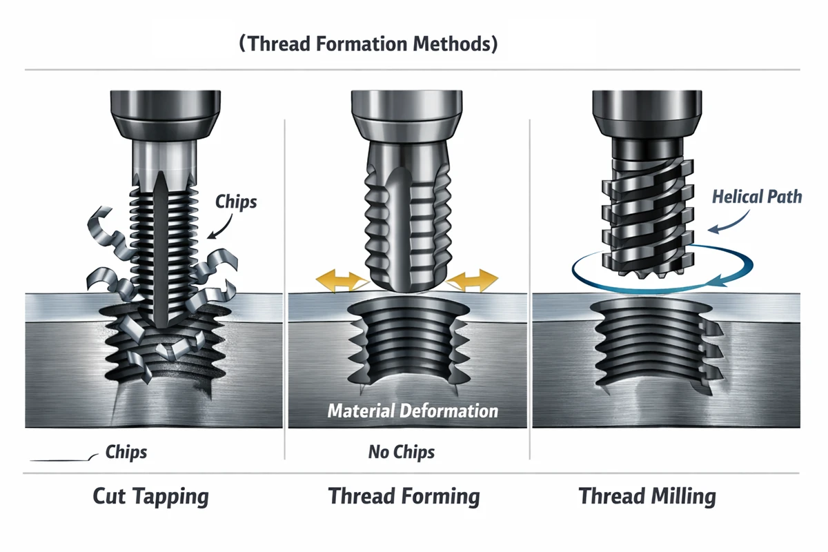
The technique chosen to create an internal thread fundamentally dictates the feature’s structural integrity, surface finish, and overall production cost.
- Tapping: Cuts threads by rotating a spiral-flute or spiral-point tap into a pre-drilled hole to remove material. This cutting action generates chips that require physical evacuation and leaves a slightly rougher surface finish compared to forming.
- Thread forming: Displaces metal outward to shape the thread profile without producing any chips. This cold-forming process leaves a burnished surface and creates threads approximately 30% stronger than cut threads, making it the preferred method for ductile materials like aluminum and low-carbon steel.
- Thread milling: Uses a rotating CNC cutter to interpolate the thread path, excelling at large diameters and difficult-to-machine alloys. The tradeoff includes slower cycle times and higher programming costs, but thread milling prevents scrapped parts caused by broken taps stuck inside blind holes.
Technical Drawing Callouts
Standard engineering callouts define the size, pitch, and tolerance of a thread, but rarely specify the exact machining process. For example:
- Metric: M8 × 1.25 – 6H
- Imperial: 5/16-18 UNC – 2B
While CAD software like SolidWorks differentiates between “Tapped” and “Threaded” holes, manufacturing drawings often leave the method open to shop-floor interpretation. To avoid confusion and control your CNC machining quote, focus on these three critical drawing details:
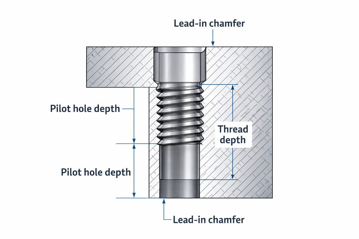
- Separate Hole Depth from Thread Depth: Mixing up pilot hole depth and full thread depth is a common error that delays production. (Note: For blind holes, always design the unthreaded pilot hole to be at least 0.5× to 1× the diameter deeper than the required thread depth to allow room for the tap tip and chip accumulation.)
- Add a Lead-In Chamfer: Specify a chamfer at the hole entry (typically 0.5 × pitch at 45°). When deciding between a chamfer vs fillet, a straight chamfer is necessary here to ensure the tap starts clean and prevents burrs.
- Optimize Thread Classes: Standard fits like 6H (metric) and 2B (UNC) keep inspection costs low. Tighter tolerance classes, up to ISO 4H/5H, demand specialized gauges and will noticeably increase pricing.
Engineering Terminology Differences
In everyday shop talk, “tapped hole” refers to the process—someone physically ran a tap into the hole. “Threaded hole” refers to the result—the hole has threads, regardless of method. When you see “threaded hole” on a print with no process note, the machinist picks the best method for the material and geometry. When you see “tapped hole,” the drawing is calling out the specific process.
In our work with overseas clients, this terminology gap causes the most RFQ confusion. A buyer writes “threaded hole” expecting tapped threads, but the shop quotes thread milling because the hole diameter is large. Clarifying the method upfront saves a revision cycle.
Side-by-Side Comparison
Before finalizing your next manufacturing print, review how these distinct terms dictate tooling choices, material compatibility, and final part performance.
| Feature | Tapped Hole (Cut Tap) | Threaded Hole (General Term) |
|---|---|---|
| Definition | Threads cut by a tap tool | Any hole with internal threads |
| Thread formation | Material removal (cutting) | Cutting, forming, or milling |
| Chip production | Yes — requires chip evacuation | Depends on method |
| Thread strength | Standard | Formed threads are ~30% stronger |
| Material range | Nearly all metals and plastics | Depends on method selected |
| Best for | General-purpose, small-to-mid diameter | Application-dependent |
| Drawing callout | Often includes process note | Specifies thread size and class only |
In short, ‘tapped’ dictates the exact manufacturing process, while ‘threaded’ only defines the final geometry.
How Tapped Hole Specs Affect CNC Machining Cost
When evaluating your files for our standard 1–3 day quote turnaround, our estimators look closely at four variables in your tapped hole spec that drive most of the cost difference: hole type, thread depth, thread diameter, and fit tolerance.
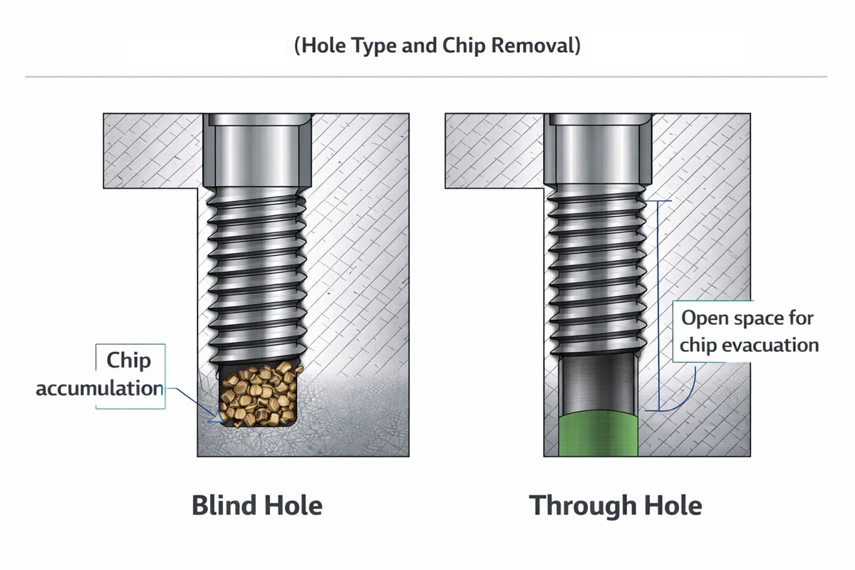
Hole Type and Chip Removal
Blind tapped holes cost more than through tapped holes. Chips have nowhere to exit in a blind hole, forcing the machinist to use peck-tapping cycles or spiral-flute taps to pull chips upward. Based on experience, blind holes in materials like stainless steel or titanium can add 20–40% to tapping cycle time compared to through holes in aluminum, purely because of chip management.
Thread Depth
Specifying threads deeper than 2× the hole diameter increases tooling costs and tap deflection risks.
- Depth ≤ 2× diameter: Uses standard tooling with no cost penalty.
- Depth 2–3× diameter: Requires extended-reach taps, adding a 15–25% cost premium.
- Depth > 3× diameter: Forces a switch to thread milling or specialty tooling, causing a significant price jump.
A standard bolt only engages 1.5× its diameter in steel before additional depth stops adding holding force.
Thread Diameter
Small taps snap easily, and a broken tap fused inside a hardened steel part often scraps the entire workpiece. In our work, we routinely help clients standardize hole sizes during free DFM reviews to mitigate these tool breakage risks.
- Threads < M3 (or #4-40): Carry high breakage risk and require slow feed rates, leading to premium pricing.
- Threads M3–M12 (or #6-32 to 1/2-13): Represent the sweet spot for rapid, reliable tapping.
- Threads > M12: Push shops toward thread milling for better economy and tool life.
Fit Tolerance
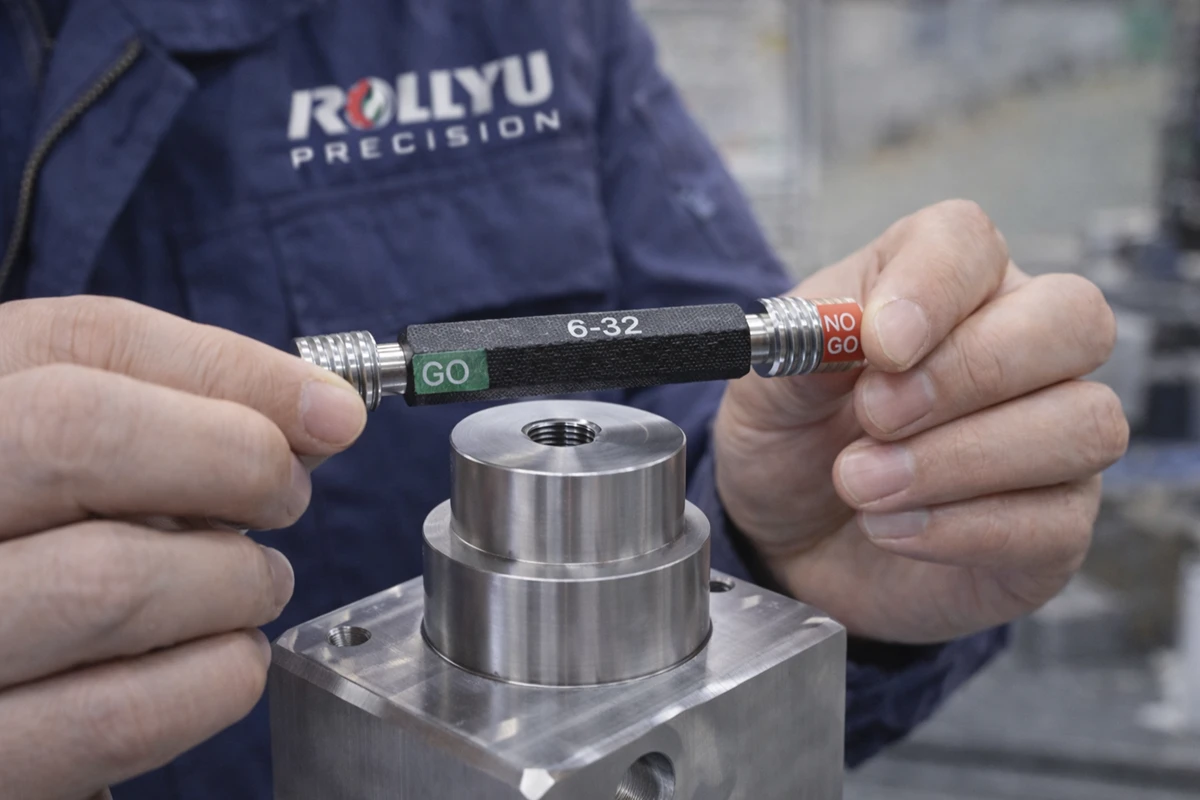
Standard tolerance classes (6H metric / 2B UNC) keep inspection costs low because operators verify them with off-the-shelf go/no-go gauges. Tight-tolerance threads demand calibrated plug gauges and CMM verification, adding $50–$200 per unique thread callout to the final inspection bill.
At Rollyu Precision, our in-house CMMs and strict ISO 9001/13485 quality controls allow us to verify tight-tolerance threads and general dimensions down to ±0.005mm. And thread accuracy up to ISO 4H/5H or ANSI class 3B. During our in-process inspection, we use thread plug gauges to verify tapped hole depth and threads every 10 pieces to ensure absolute consistency.
However, unless you are designing medical devices or semiconductor components that strictly demand a documented precision-fit, we still recommend standard-class threads to keep your machining quote optimized.
How to Choose the Right Internal Thread for Your Part
Getting the right internal thread means matching four variables to your part: material, hole geometry, tolerance, and thread standard.
Match Thread Type to Your Material
Thread forming taps work best for ductile metals like copper and aluminum. Whether you are comparing Aluminum 6061 vs 7075 for your specific part, this method creates threads that run 30% stronger while producing zero chips.
Standard cut tapping remains the default for steel and stainless steel. Thread milling is the safest choice for titanium, Inconel, and diameters above M16, preventing expensive scrap from broken taps.
Cut tapping at reduced speeds handles advanced plastics like PEEK, since thread forming pressure will crack brittle polymers.
Account for Hole Depth and Type
- Through holes: Use spiral-point taps to push chips forward for the fastest cycle times.
- Blind holes ≤ 2×D: Use spiral-flute taps to pull chips out reliably.
- Blind holes > 2×D: Switch to thread milling to prevent chip packing at the bottom of the bore.
- Intersecting holes: Thread milling controls cutting forces and stops thin-wall blowout.
Specify the Right Fit Tolerance
Standard 6H (metric) and 2B (UNC) classes handle over 90% of mechanical assemblies. Reserve tighter 5H or 3B classes strictly for precision alignment, and specify interference 4H5H threads only for verified press-fit or fluid sealing applications.
Pick the Right Thread Standard
Metric (M-series) provides the widest global fastener availability for new designs. UNC (Unified National Coarse) resists cross-threading in soft materials due to its wider pitch, while UNF (Unified National Fine) holds secure in thin-wall parts and high-vibration environments. Mixing thread families on a single part drives up sourcing and tooling complexity.
FAQ
What’s the Difference Between a Tapped Hole and Using a Nut?
A tapped hole cuts threads directly into the base material, requiring a minimum material thickness of 1.5× the bolt diameter to hold tension. Nuts and clearance holes work best for thin sheet metal or joints requiring frequent disassembly, since cut threads in soft aluminum strip out after 15–20 torque cycles.
Can a Stripped Tapped Hole Be Repaired?
Yes, by installing a thread insert (like a Helicoil) or tapping to the next larger standard size. Helicoils are the industry standard because they maintain the original bolt size and actively increase thread strength in soft metals like aluminum or magnesium. To prevent stripping in production, specify thread-forming taps or pre-installed inserts for any material softer than HRC 25.
How Do You Specify a Tapped Hole on a Technical Drawing?
A complete drawing callout includes five specific parameters: thread size, pitch, tolerance class, thread depth, and pilot hole depth. For example, a correct specification reads: M8 × 1.25 – 6H, 15mm deep, in Ø7.0 hole, 20mm deep.
Conclusion
The difference between a tapped hole and a threaded hole comes down to specificity: tapping is one method, threaded hole is the result. Choosing the right thread formation method, specifying accurate callouts, and matching thread specs to your material and application directly impacts part cost, quality, and lead time.
When you’re sourcing CNC machined parts with internal threads, send your drawings to a shop that understands these distinctions. At Rollyu, our engineering team reviews every threaded feature before production—optimizing tap selection, thread depth, and tolerance class to keep your parts functional and your costs down.