According to Global Growth Insights, Swiss machining accounts for roughly 29% of the global precision machining market, valued at $4.09 billion in 2025. Medical, semiconductor, and electronics makers drive that demand, because their parts are too small and too precise for standard turning.
This article covers how Swiss machining works, from the guide bushing and bar-feed cycle to achievable tolerances and material compatibility.
Why Swiss Machining Starts with the Guide Bushing
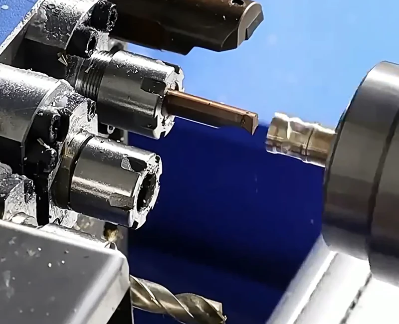
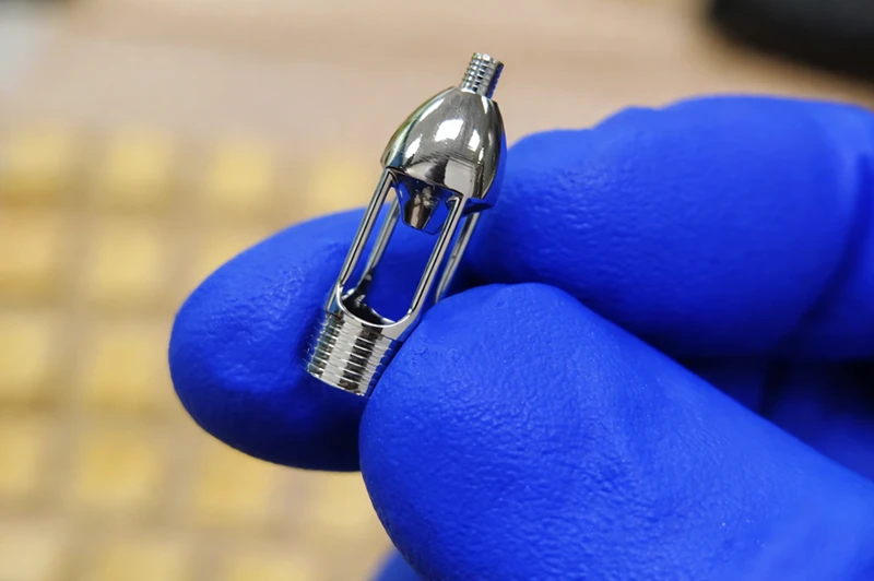
The guide bushing holds bar stock at the exact point of cut. The sliding headstock, tool positioning, and bar-feed cycle all depend on that fixed grip.
Holding Stock at the Cutting Point
The guide bushing grips bar stock within millimeters of where the cutting tool contacts it. In standard turning, the chuck sits several inches back from the cut zone, leaving an unsupported span between the grip point and the tool. That span lets the workpiece flex under cutting pressure.
Feeding Stock Through the Sliding Headstock
The sliding headstock moves along the Z-axis, pushing bar stock through the guide bushing toward the cutting tools. The guide bushing stays fixed. As the headstock advances, the cutting point remains stationary while fresh stock feeds into it, keeping the support zone consistent across the full length of the part.
Preventing Workpiece Deflection
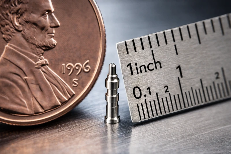
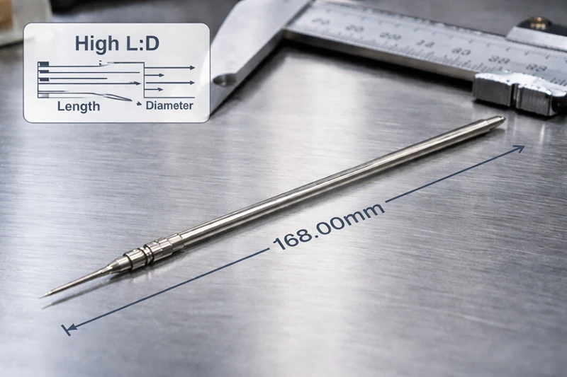
The guide bushing prevents workpiece deflection by gripping bar stock at the cut zone itself. Cutting force never lands on an unsupported span, so the bar cannot flex. Long, slender parts with length-to-diameter ratios above 4:1 hold tolerance where standard turning produces measurable runout.
The Swiss Machining Process Step by Step
Swiss machining runs as a continuous bar-feed cycle, where each step hands off directly to the next.
Step 1: Loading the Bar Stock
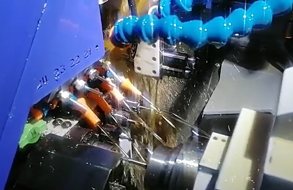
The operator feeds bar stock through the machine’s collet and into the guide bushing. Bar diameter typically runs from 1 mm to 32 mm depending on the machine, and stock loads in standard 12-foot (3.6 m) lengths. Once the collet clamps and the guide bushing seats the bar, the machine runs unattended until the stock is consumed.
Step 2: Rotating and Advancing the Bar Stock
The spindle spins the bar stock while the sliding headstock pushes it forward through the guide bushing toward the tool zone. Spindle speed typically ranges from 2,000 to 10,000 RPM, dialed to the material and cut diameter.
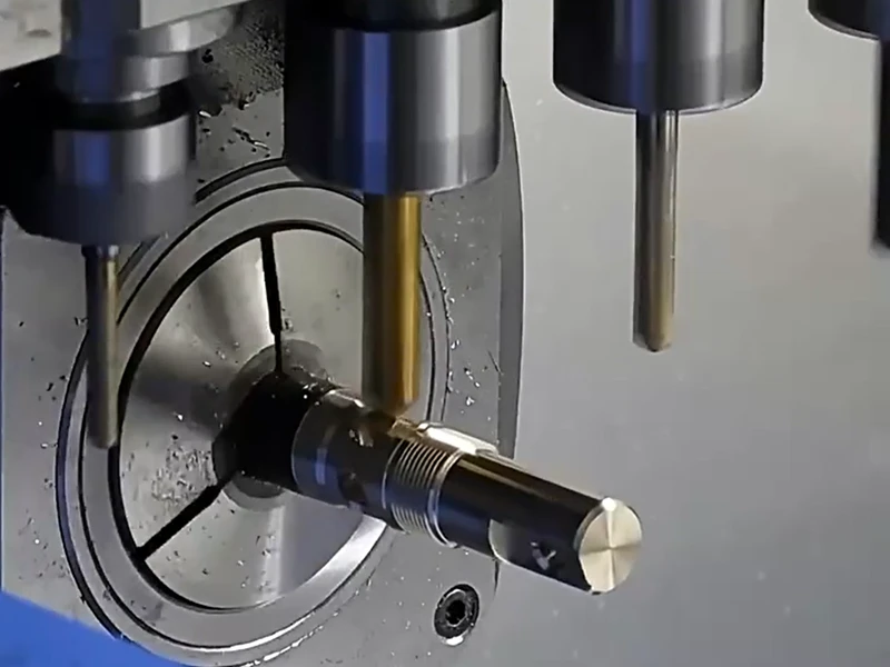
Step 3: Engaging the Gang Tool Slide
The gang tool slide carries multiple cutting tools on a single flat plate, letting the CNC program sequence turning, drilling, threading, and grooving without moving the workpiece. Machines equipped with live tooling can also run cross-drilling and milling operations in the same cycle, cutting cycle time significantly on parts with off-axis features. Each tool engages at the same fixed cut zone that the guide bushing supports.
Step 4: Cutting Off and Transferring to the Sub-Spindle
A cutoff tool severs the part from the bar stock once the front-end features are complete. The sub-spindle grips the part before the cutoff completes, so the part never drops free and its axial position stays registered for rear-face machining.
Step 5: Backworking the Rear Features
The sub-spindle presents the severed part’s rear face to the back-working tools while the main spindle has already started cutting the next part. Rear bores, chamfers, and cross-holes are machined here. The part stays fixtured throughout, keeping rear features concentric with front features.
Step 6: Ejecting the Finished Part
The sub-spindle releases the finished part into a parts catcher, which cushions the drop and prevents surface damage on precision components. At the same time, the main spindle advances fresh bar stock into the cut zone, starting the next cycle.
Swiss Machining Tolerances and Material Compatibility
Swiss machining is built for parts where standard turning runs out of precision.
Dimensional Tolerances
Swiss machining holds dimensional tolerances as tight as ±0.002 mm on critical features, according to Rollyu Precision. Standard production runs typically target ±0.005 mm, which covers most medical, semiconductor, and electronics applications.
Surface Finish
As-machined Swiss turned parts come off the spindle at Ra 1.6–3.2 μm (63–125 µin). Parts that need smoother contact surfaces, such as implants or fluid fittings, reach Ra 0.4–0.8 μm (16–32 µin) with polishing. Electropolishing pushes surface finish below Ra 0.2 μm for critical cleanliness and corrosion specs. Advanced partners like Rollyu Precision routinely achieve this standard.
Material Compatibility
- Aluminum 6061, 7075: fast to cut, ready for standard anodizing processes, suited for lightweight structural parts.
- Stainless Steel 303, 304, 316L, 17-4PH: corrosion-resistant grades for medical and semiconductor use.
- Titanium Grade 2, Grade 5 (Ti-6Al-4V): non-magnetic, biocompatible, carries biocompatibility certification for medical and dental applications.
- Brass C360: free-machining, high-volume connectors and fittings.
- Inconel: heat-resistant, for high-temperature applications.
- PEEK, PTFE, Delrin: suited for weight-sensitive, chemically exposed, or electrically insulated parts.
Free-machining alloys like Brass C360 and Aluminum 6061 run well in both guide bushing and guideless configurations. Harder materials like Titanium and Inconel require the guide bushing setup to keep cutting forces under control.
Which Industries Rely on Swiss Machining
Swiss machining supplies the precision CNC machined parts that medical, semiconductor, and dental manufacturers cannot source from standard turning.
Medical Devices
Swiss machining cuts sub-millimeter surgical components like robotic arm joints and implantable casings. Medical OEMs rely on the sliding headstock to hold tolerances down to ±0.005 mm on tough materials like Titanium Grade 5 and PEEK.
Cutting these implants in a single setup prevents handling errors, helping ISO 13485-certified shops like Rollyu Precision secure full lot traceability.
Semiconductor
Semiconductor fabrication uses Swiss machining to turn wafer alignment systems and vacuum chamber flanges. Swiss turning centers hold dimensional tolerances down to ±0.002 mm on Aluminum 6061 and 316L Stainless Steel to prevent the particle contamination that ruins wafer yields. Processing these metals in a single cycle delivers leak-free fixtures ready for immediate cleanroom packaging.
Dental Equipment
Dental equipment manufacturers use Swiss machining to turn compact parts like intraoral scanner brackets and custom abutment fixtures. The continuous bar-feed cycle cuts Titanium and 316L Stainless Steel into smooth, vibration-free components that fit directly into chairside CAD/CAM units.
Machining these clinical geometries complete in one run drops biocompatible parts right into the catcher, stopping surface damage and skipping secondary handling.
When Swiss Machining Is the Right Choice
Engineers specify Swiss machining when standard lathes drop tolerances on slender parts and high-volume micro-components.
Part Geometry and L:D Ratio
Swiss turning centers process slender components with length-to-diameter (L:D) ratios exceeding 4:1 while preventing workpiece deflection. Standard lathe chucks leave long bar ends unsupported, causing chatter under cutting pressure.
Feeding stock through a guide bushing directly at the cut zone keeps the material rigid. This structural grip easily turns pins and medical shafts hitting L:D ratios of 10:1 or 20:1. The gang tool slide cuts cross-holes and milled flats in one cycle, stopping operators from moving fragile parts to secondary mills.
Tolerance and Volume Requirements
Swiss machines run automated batches of 50 to 10,000+ parts while holding tolerances down to ±0.005 mm. Setting up the guide bushing takes extra time, but the continuous bar-feed cycle quickly pays off that investment. Once cutting parameters settle in, the machine drops finished parts into the catcher unattended. Manufacturers justify Swiss capacity using three hard thresholds:
- Length-to-diameter ratio: Machining slender shafts from 4:1 up to 20:1 without mid-cut deflection.
- Dimensional precision: Holding tolerances down to ±0.005 mm (±0.0002″) on critical mating features.
- Production scaling: Running automated batches of 50 to 10,000+ units to drive down per-part costs.
FAQ
How Long Does Swiss Machining Setup Typically Take?
Setting up a Swiss machine takes 4 to 8 hours depending on part geometry and tool count. This timeframe covers mounting the guide bushing, indexing gang tools, and programming the sub-spindle. The continuous bar-feed cycle quickly pays off that upfront labor by running unattended batches of 100 to 10,000+ parts.
What Is the Maximum Bar Stock Diameter for Swiss Machining?
The maximum bar stock diameter for most Swiss lathes is 32 mm (1.25 inches). These machines excel at cutting small-diameter components ranging from 1 mm to 20 mm to hit micron-level accuracy. Manufacturers route parts over 32 mm to fixed-headstock lathes, dropping the guide bushing entirely because thicker material holds its own rigidity.
Does Swiss Machining Require a Guide Bushing for Every Job?
No, modern Swiss machines run in chucker mode for components with length-to-diameter (L:D) ratios under 3:1. Dropping the guide bushing lets operators feed standard bar stock and shortens the material remnant, instantly cutting waste costs. The guide bushing remains mandatory for slender parts crossing the 4:1 L:D threshold, keeping the bar rigid to hold tolerances down to ±0.005 mm.
Conclusion
Swiss machining solves the deflection and runout issues that break standard turning operations. Gripping bar stock through a guide bushing directly at the cut zone keeps slender materials rigid. This mechanical support holds ±0.005 mm tolerances on components hitting L:D ratios up to 20:1.
Delivering these finished parts in a single setup stops secondary handling and drives down high-volume production costs. Partnering with an experienced machining facility like Rollyu Precision ensures these advantages scale seamlessly from engineering prototypes to full-volume runs.