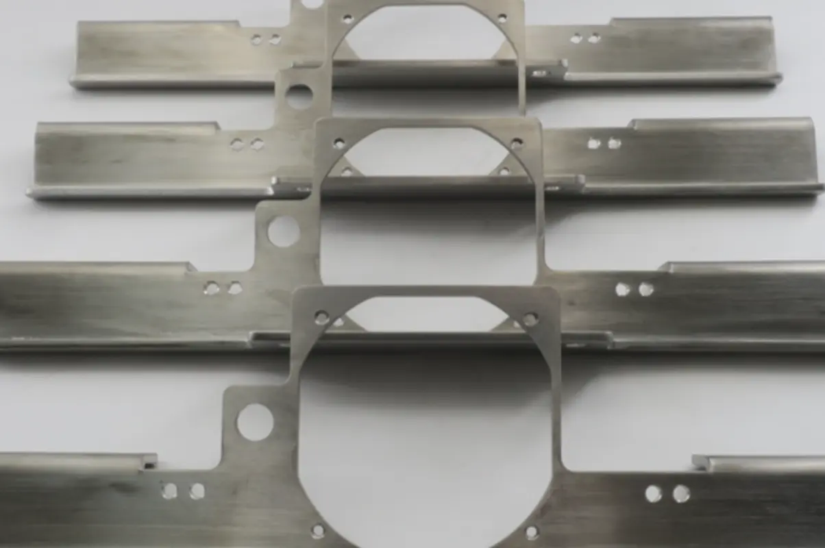

Adjusting the K-factor shifts a bent bracket’s calculated flat length because it repositions the assumed neutral axis within the sheet, directly altering the bend allowance. When formed leg dimensions, sheet thickness, inside radius, and bend angle remain constant, a larger K-factor generates a longer developed blank. This formula provides a geometric starting point in CAD, which fabrication teams adjust to match real press-brake tooling and material test bends.
What Does K-Factor Change in a Flat Pattern?
K-factor expresses the location of the neutral axis as a ratio: the distance from the inside bend surface to the neutral layer divided by the total sheet thickness. Across the bend, this neutral layer undergoes neither tension nor compression.
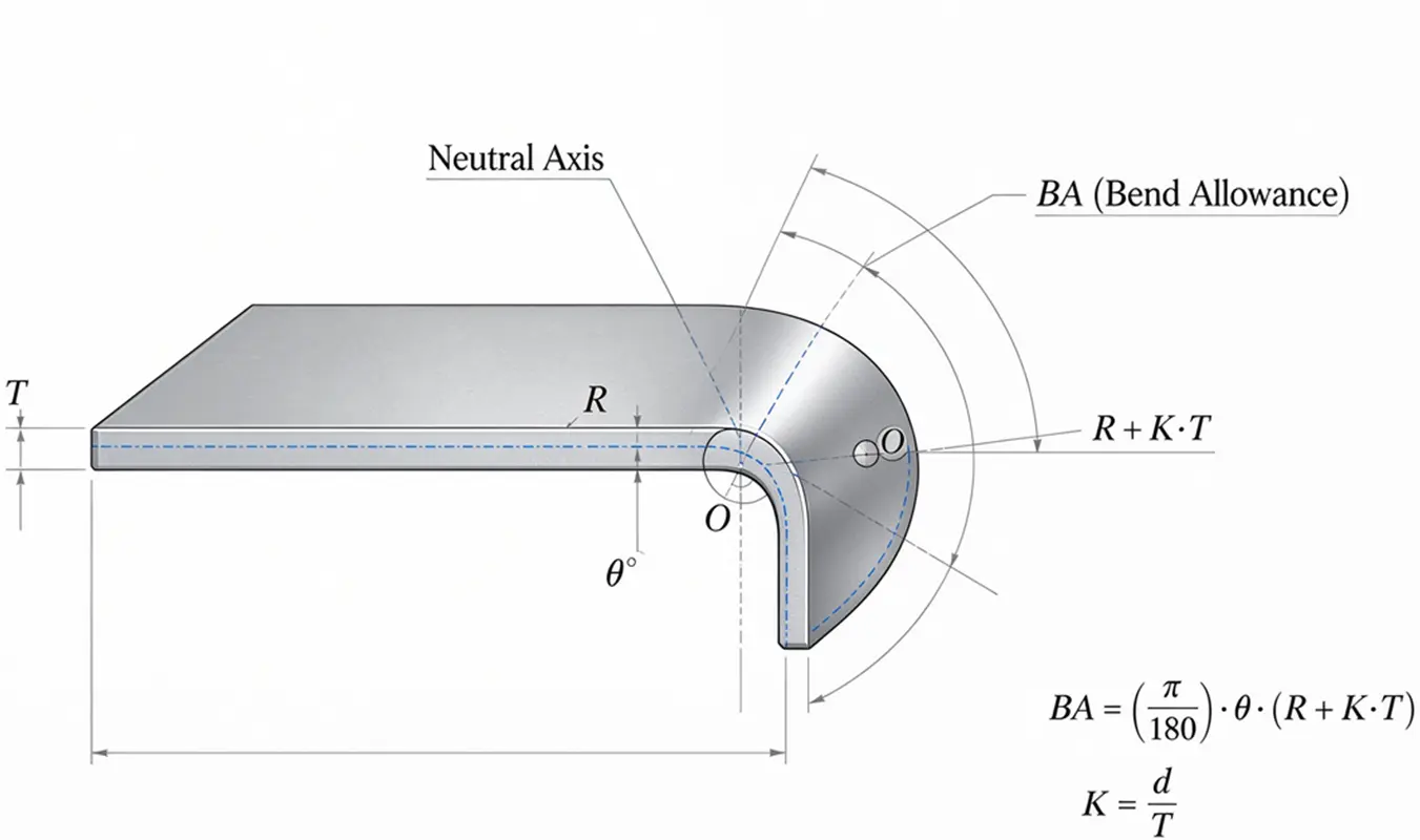
Standard CAD systems like SOLIDWORKS define the resulting bend allowance (the arc length along this neutral layer) as:
- BA = (π × θ / 180) × (R + K × T)
Where:
- BA is bend allowance (neutral-axis developed length)
- R is the formed inside bend radius
- T is sheet thickness
- K is the K-factor ratio
- θ is the bend angle from flat in degrees (deflection angle), rather than the remaining included angle between finished legs
Increasing K pushes the calculated neutral axis toward the outer bend surface. This increases the effective arc radius R + K × T, expanding the calculated bend allowance and lengthening the flat blank.
Which Bracket Dimensions Go Into the Calculation?
Accurate blank calculation requires sticking to one dimensional basis. In the reference schematic below, each formed outside leg length extends from the cut edge to the outside virtual sharp, the theoretical intersection point of the two outside planes:
In this 90° L-bracket example, the outside legs measure 60 mm and 40 mm, sheet thickness is 2 mm, and the formed inside radius is 1 mm.
At a 90° bend angle, the outside setback from each tangency point to the virtual sharp is:
- OSSB = (R + T) × tan(θ / 2) = (1 + 2) × tan(45°) = 3.000 mm
Because outer leg dimensions extend to the virtual sharp, the flat pattern uses bend deduction:
- BD = 2 × OSSB − BA = 6.000 − BA
- Flat Length = Leg 1 + Leg 2 − BD = 60 + 40 − BD
If drawing dimensions instead run between bend tangency points (the straight flat segments), the blank length equals the sum of those straight sections plus the bend allowance BA. Mixing virtual-sharp dimensions with bend allowance produces an undersized part.
How Do Two K-Factor Assumptions Change the Flat Length?
Holding the formed bracket geometry fixed, altering only the K-factor demonstrates how CAD defaults shift the cut file. The table compares two common baseline settings, K = 0.30 and K = 0.45:
| K-Factor Setting | Bend Allowance, BA = (π/2)(1 + 2K) | Outside Setback (Each Leg) | Bend Deduction, BD = 6 − BA | Calculated Flat Length, 100 − BD |
|---|---|---|---|---|
| 0.30 | 2.513 mm | 3.000 mm | 3.487 mm | 96.513 mm |
| 0.45 | 2.985 mm | 3.000 mm | 3.015 mm | 96.985 mm |
The 0.15 increase in K-factor expands the bend allowance by 0.15 × π ≈ 0.471 mm. This reduces the bend deduction by the same amount, yielding a 96.985 mm blank instead of 96.513 mm (a 0.472 mm difference across rounded table figures).
Checking this via the tangency basis confirms the result: subtracting the 3.000 mm setback leaves straight flats of 57.000 mm and 37.000 mm. Adding either bend allowance to 57 + 37 = 94.000 mm delivers the identical flat blank lengths.
What Does the Calculated Flat Length Leave Unconfirmed?
A CAD formula assumes an ideal inside radius and a uniform material response that rarely matches raw metal behavior. Several physical variables alter actual bend results:
- Material temper and yield strength: High-strength alloys resist deformation and shift the neutral axis differently than annealed materials.
- Tooling geometry: Air bending over a wide V-die opening produces a naturally floating inside radius, distinct from bottoming or coining over a sharp punch.
- Grain direction: Bending across the sheet rolling grain yields slightly different springback and elongation than bending parallel to it.
K-factor also does not automatically solve for press-brake springback compensation or safe minimum bend radii to prevent outer-surface cracking. Major CAD packages, including Autodesk Inventor and SOLIDWORKS, allow engineers to bypass theoretical K-factor formulas by assigning empirical bend deduction tables derived from specific shop tooling and material gages.
What Should the Design Engineer Send for Bend Review?
To ensure critical fitment, engineering drawings must explicitly dimension key formed features, hole centerlines, and mating surfaces, noting whether callouts measure to outside virtual sharps or bend tangencies.
When preparing files for Rollyu Precision, provide the 3D formed model, 2D drawing with tolerance limits, specified alloy and temper, target inside bend radius, and the provisional unfold rule used in CAD.
Through dedicated sheet metal fabrication services, press-brake operators evaluate the CAD bend deductions against established tooling charts or run a physical test coupon. The fabricator then fine-tunes the DXF blank profile to absorb tooling-specific elongation while holding the critical formed dimensions on the assembly print.
Frequently Asked Questions
How Do You Measure Bend Deduction With a Trial Bend?
Cut a rectangular test strip of known length, bend it 90° on the production tooling, and measure both formed outside legs to the virtual sharp using calipers or an optical comparator.
Calculate the measured bend deduction by subtracting the original blank length from the sum of the finished leg dimensions:
- BD = Leg A + Leg B − Blank Length
Feed this verified value directly into the CAD bend deduction table for that specific sheet thickness, punch, and V-die combination.
Can You Use One K-Factor for Another Bend Angle or Inside Radius?
A single K-factor should not be applied across varying bend radii or sheet thicknesses. The position of the neutral axis depends heavily on the ratio of inside bend radius to sheet thickness ($R/T$).
In sharp bends where $R/T$ is small (such as $R \le T$), plastic deformation concentrates on the inner fibers, forcing the neutral axis closer to the inside face ($K$ often drops below 0.35). As $R/T$ increases above 3.0, stress distributes more symmetrically across the section, moving the neutral axis closer to the sheet midpoint ($K$ approaches 0.50). Bending beyond 90° also increases compressive displacement, requiring dedicated bend deductions or coupon verification.
How Should You Check Hole Locations After Changing the Unfold Rule?
Changing the unfold rule changes the developed blank length, which repositions flat-pattern cutouts relative to the bend line. On the flat DXF, a hole located on an unformed leg stays at its fixed distance from the free edge, but its position relative to the bend line shifts by the change in bend deduction.
When updating CAD unfold settings, regenerate the flat pattern and re-verify hole-to-hole centerlines across the bend against the formed 2D drawing. Furthermore, confirm that all hole edges sit outside the bend deformation zone (typically at least R + 2T away from the bend tangency) to prevent oval distortion during forming.